EP0837523B1 - Adaptive antenna - Google Patents
Adaptive antenna Download PDFInfo
- Publication number
- EP0837523B1 EP0837523B1 EP97308253A EP97308253A EP0837523B1 EP 0837523 B1 EP0837523 B1 EP 0837523B1 EP 97308253 A EP97308253 A EP 97308253A EP 97308253 A EP97308253 A EP 97308253A EP 0837523 B1 EP0837523 B1 EP 0837523B1
- Authority
- EP
- European Patent Office
- Prior art keywords
- beams
- antenna
- sector
- communication
- adaptive antenna
- Prior art date
- Legal status (The legal status is an assumption and is not a legal conclusion. Google has not performed a legal analysis and makes no representation as to the accuracy of the status listed.)
- Expired - Lifetime
Links
Images


Classifications
-
- H—ELECTRICITY
- H01—ELECTRIC ELEMENTS
- H01Q—ANTENNAS, i.e. RADIO AERIALS
- H01Q3/00—Arrangements for changing or varying the orientation or the shape of the directional pattern of the waves radiated from an antenna or antenna system
- H01Q3/26—Arrangements for changing or varying the orientation or the shape of the directional pattern of the waves radiated from an antenna or antenna system varying the relative phase or relative amplitude of energisation between two or more active radiating elements; varying the distribution of energy across a radiating aperture
- H01Q3/2605—Array of radiating elements provided with a feedback control over the element weights, e.g. adaptive arrays
-
- H—ELECTRICITY
- H01—ELECTRIC ELEMENTS
- H01Q—ANTENNAS, i.e. RADIO AERIALS
- H01Q25/00—Antennas or antenna systems providing at least two radiating patterns
Definitions
- the present invention relates to an adaptive antenna for use with a base station for a mobile communication system, a local area radio communication system, and so forth.
- an antenna that form a plurality of sector beams is used.
- an area of 360 degrees on a horizontal plane of the base station is covered with a plurality of beams.
- six beams with a beam width of 60 degrees are disposed in the circumferential direction.
- a dipole antenna with reflector is known. In this antenna, the beam width depends on the size of the reflector and the height of the dipole to the reflector.
- such an antenna that form a plurality of beams does not have a means for controlling the difference of communication amounts of beams in the service area that the base station covers. For example, in an area of a particular sector beam, the communication amount is very large. In an area of another sector beam, the communication amount is very small. Such a situation often takes place.
- the communication amounts are unbalanced among beams on the time base, such a problem can be solved by initially changing the beam widths of sector beams or initially changing the number of channels that are accommodated in the individual sectors. But in the case that unbalanced communication traffic may often change, it is difficult to overcome such a problem by using the conventional antenna.
- WO 95/09490 relates to an adaptive antenna which comprises means to output a wide beam and a narrow beam.
- the wide beam and narrow beam being selected depending on the class of communication required.
- the wide beam is generally used for call set up.
- An object of the present invention is to provide an adaptive antenna that allows patterns of a plurality of beams that cover a predetermined service area to be flexibly varied corresponding to communication environments.
- Another object of the present invention is to provide an adaptive antenna that allows the communication amount to be well-balanced among beams and the communication capacity of the base station to be effectively used.
- a further object of the present invention is to provide an adaptive antenna that allows the patterns of beams to be stably and optimally to be controlled so as to well-balance the communication amounts among beams.
- the present invention provides an adaptive antenna in accordance with claim 1.
- the controlling means preferably controls the pattern (beam width and direction) of each of the beams corresponding to the detected communication amount so as to cause the communication amounts of the beams to be nearly matched.
- patterns of a plurality of beams that cover a predetermined service area can be flexibly varied corresponding to variations of communication environments. Consequently, the communication amounts of beams can be prevented from deviating. As a result, the communication capacity of the base station can be effectively used. Thus, the number of terminals that can be accommodated can be increased.
- the adaptive antenna of the present invention preferably has a plurality of first antenna elements and a plurality of second antenna elements, the first antenna elements composing a transmitting antenna portion, the second antenna elements comprising a receiving antenna portion and being analogous to the transmitting antenna portion, the ratio of the size of the transmitting antenna portion to the size of the receiving antenna portion being equal to the reciprocal of the ratio of a transmission frequency to a reception frequency.
- the shapes of the transmitting sector beams are always the same as the shapes of the receiving sector beams. Consequently, a communication defect due to the difference of shapes of sector beams can be prevented. Thus, good communication environments can be always maintained.
- the controlling means preferably has a means for controlling a pattern (width and direction) of each of the beams when the maximum communication amount of each of the beams exceeds a predetermined value.
- a pattern width and direction
- the patterns of individual beams are controlled so as to well-balance the communication amounts among the beams. Consequently, since an unnecessary controlling process is omitted, the adaptive antenna can be stably controlled.
- the controlling means preferably controls the beam widths of at least a first beam and a second beam, the first beam having the maximum communication amount, the second beam having the minimum communication amount.
- the controlling means controls the beam widths of at least a first beam and a second beam, the first beam having the maximum communication amount, the second beam having the minimum communication amount while keeping the sum of the beam width of each beam nearly constant.
- Fig. 1 is a block diagram showing the structure of an adaptive antenna according to the embodiment of the present invention.
- the adaptive antenna according to the embodiment of the present invention is an antenna for use with a base station.
- the adaptive antenna covers an area of 360 degrees on a horizontal plane of the base station with six sector beams.
- the adaptive antenna has a receiving antenna portion 1 and a transmitting antenna portion 2.
- the receiving antenna portion 1 and the transmitting antenna portion 2 each form six sector beams with a 12-element array.
- the sizes of the receiving antenna portion 1 and the transmitting antenna portion 2 and the intervals of the antenna elements depend on the frequency bands (or wave lengths) of radio waves that are received and transmitted. In reality, the receiving antenna portion 1 and the transmitting antenna portion 2 have different sizes and are analogous to each other.
- the shape parameter of the transmitting antenna portion 2 is equal to [reception frequency/transmission frequency] times the shape parameter of the receiving antenna portion 1. For example, assuming that the transmission frequency is 1 GHz and the reception frequency is 2 GHz, the size of the transmitting antenna portion is twice the size of the receiving antenna portion.
- each antenna portion depends on the wave length of the radio wave for use.
- the intervals of the antenna elements are constant regardless of the wave length of the radio wave.
- the beam pattern of the receiving antenna portion becomes the same as the beam pattern of the receiving antenna portion.
- a signal received by an antenna element of the receiving antenna portion 1 is amplified by a reception signal amplifying portion 3.
- the amplified signal is weighted by a weight setting portion 5.
- the resultant signal is supplied to a receiving portion 8.
- a signal that is output from a transmitting portion 9 is distributed and then weighted by a weight setting portion 6.
- the weighted signal is amplified by a transmission signal amplifying portion 4.
- the amplified signal is sent to the transmitting antenna portion 2.
- the receiving portion 8 converts the received RF signal into a base band signal.
- the transmitting portion 9 converts a modulated base band signal into an RF signal.
- a signal processing portion 10 modulates/demodulates a base band signal.
- a controlling portion 11 controls signals to be sent to the outside and manages radio channels in association with the signal processing portion 10.
- the controlling portion 11 detects the communication amount for each sector.
- the communication amount can be obtained corresponding to for example the number of terminals that are communicating for each sector and the number of channels in operation.
- An antenna controlling portion 7 determines an optimum exciting weight of each antenna element corresponding to information of the communication amount for each sector received from the controlling portion 11 and sends the obtained exciting weight to both a reception signal weight setting portion 5 and a transmission signal weight setting portion 6. At this point, the same exciting weight is set to the reception signal weight setting portion 5 and the transmission signal weight setting portion 6.
- Fig. 2 is a schematic diagram showing the structure of the weight setting portion and the amplifying portion of the receiving antenna portion.
- the reception signal amplifying portion 3 is composed of the low noise amplifier 41 and the distributing units 42.
- the weight setting portion 5 has beam forming circuits (BFN) 46, 47, 48, 49, 50, and 51 corresponding to respective sectors. Each BFN sets up exciting weights for seven (or eight) antenna elements.
- the weighted signals are combined for each sector by a combining unit 45.
- the combined signal is output to the receiving portion 8.
- Amplitude weights are set up by variable attenuators 43.
- Phase weights are set up by variable phase shifters 44.
- the structure for controlling the exciting weights is also provided to the transmitting antenna portion.
- high power amplifiers HPA
- the positions of the distributing unit and the combining unit of the receiving antenna portion are reversed in the transmitting antenna portion.
- Fig. 3 is a top view showing the antenna.
- 12 antenna elements are disposed at respective vertexes of a dodecagon.
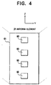
- Fig. 4 is an external view showing an antenna element 21.
- the antenna element 21 is composed of a plurality of planer antenna members 60 that are arranged in the vertical direction on a dielectric substrate 61.
- the antenna element may be composed of a single antenna member.
- a microstrip antenna or a dipole with a reflector can be used instead of the planer antenna members.
- a series feeding method or a tournament feeding method using microstrip lines can be used as a feeding method.
- the features of the adaptive antenna according to the present invention are the controlling portion 11 as a means for detecting the communication amount for each beam and the antenna controlling portion 7 as a controlling means for controlling each beam pattern corresponding to the information of the detected communication amount.
- the exciting weight of each antenna element is controlled corresponding to the detected communication amount and thereby the pattern of each beam is controlled, the deviation of the communication amounts of beams can be flexibly compensated.
- the communication capacity of the base station can be effectively used.
- the number of terminals that can be accommodated to the base station can be increased. Consequently, the cost can be equivalently decreased.
- the shape of the transmitting antenna portion is analogous to the shape of the receiving antenna portion.
- the ratio of the size of the transmitting antenna portion to the size of the receiving antenna portion is equal to the reciprocal of the ratio of the transmission frequency to the reception frequency.
- Fig. 5 is a flow chart showing a process of the antenna controlling portion 7.
- the antenna controlling portion 7 determines the beam direction and the beam width of each sector so that the communication amount of each beam is equalized corresponding to the information of the communication amount for each beam received from the controlling portion 11.
- the antenna controlling portion 7 obtains exciting weights for forming such beams and outputs the exciting weights to the weight setting portions 5 and 6.
- each sector beam is switched in five levels that are 30 degrees, 45 degrees, 60 degrees, 75 degrees, and 90 degrees.
- the beam width as the initial value (nominal value) is 60 degrees.
- the antenna controlling portion 7 inputs information of the communication amount for each sector from the controlling portion 11 (at step S1).
- the antenna controlling portion 7 obtains the average of the communication amount per unit time for each sector and determines the most crowded sector and the most uncrowded sector.
- the antenna controlling portion 7 determines a desired pattern (beam direction and beam width) of each sector beam corresponding to the following rules (at step S2).
- Rule 1 The beam width of a sector whose communication amount is the largest (most crowed) is narrowed by one level (for example, the beam width is switched from 60 degrees to 45 degrees).
- Rule 2 The beam width of the sector whose communication amount is the smallest (most uncrowded) is widened by one level (for example, the beam width is switched from 60 degrees to 75 degrees).
- the antenna controlling portion 7 obtains the antenna exciting weight for the desired pattern of each sector beam (at step S3).
- the antenna controlling portion 7 outputs a weight control signal for setting the obtained exciting weight to the weight setting portions 5 and 6 (at step S4).
- an exciting weight there are several methods.
- an optimum pattern is selected from several patterns that have been prepared.
- an exciting weight is converged by, for example, a method of steepest descent so that a mean square error with a desired pattern becomes minimum.
- Step S2 to step S4 are repeated until the difference between the communication traffic amounts of sectors becomes a predetermined value or less or until the beam width of a particular sector of which communications concentrates cannot be narrowed.
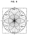
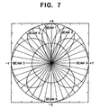
- Fig. 6 shows an arrangement of patterns of sector beams in the case that the beam widths thereof are 60 degrees.
- patterns are varied as shown in Fig. 7.
- the beam widths of sector beams (beams 1, 2, and 6) of which the communication amounts increase become narrow.
- the beam widths of sector beams (beams 3, 4, and 5) of which the communication amounts are relatively small become wide.
- the beam directions of individual sectors generally deviate in the +X direction.
- Such patterns are effective in the case that a place where people gather (for example, a station, an office district, an event hall, or the like) is present in a single direction viewed from the base station.
- Fig. 8 shows an arrangement of patterns in the case that the users gather in both the +X direction and -X direction.
- the beam widths of the sectors in the +X direction and -X direction become narrow.
- the beam widths of the other sectors become wide.
- Such patterns are effective in the case that the base station is disposed in the middle of a main road having heavy traffic.
- Fig. 9 shows patterns in the case that users gather in the direction of X > 0.
- Such patterns are effective in the case that the base station is disposed near seashore or a mountain region and thereby the distribution of the users is geographically unstable.
- the distribution of the users in the area that the base station covers can be compensated.
- the communication amounts of beams that are unbalanced due to the influences of geographical and traffic conditions can be compensated.
- the communication amounts of beams that are unbalanced due to temporal fluctuations can be compensated.
- the adaptive antenna according to the present invention can very flexibly handle the variation of the communication state in the service area that the base station covers.
- the adaptive antenna has very high use efficiency.
- the adaptive antenna according to the present invention can equivalently increase the number of users (terminals) that can be accommodated several times as many as the conventional antenna has.
- the present invention is not limited to the above-described embodiment. In other words, the present invention has other embodiments.
- the patterns of individual beams are controlled in such a manner that the amount of the decrease of beam widths of the sector beams that are narrowed becomes equal to the amount of the increase of the beam widths of the sector beams that are widened.
- the total of the beam widths of all the beams is kept constant.
- the angular area covered with all sector beams can be more stably covered.
- the beam patterns may be controlled in such a manner that the amount of the decrease of the beam widths of sector beams that are narrowed becomes smaller than the amount of the increase of sector beams that are widened in as long as the difference of each value is smaller than a predetermined threshold value.
- beam patterns other than a beam with the largest communication amount and a beam with the smallest communication amount are controlled, it is preferably to fix the beam widths and vary only the beam directions. Thus, the beam patterns that cover one service area can be effectively maintained.
- the entire antenna can be simply controlled.
- An adaptive antenna has a storing unit and an exciting weight information selecting means.
- the storing unit stores exciting weight information of each antenna element so as to accomplish the optimum pattern of each beam corresponding to the communication amount thereof.
- the exciting weight information selecting means selects relevant exciting weight information from the storing unit.
- the optimum exciting weight can be set up by selecting relevant exciting weight information in the storing unit.
- the optimum exciting weight can be obtained more quickly than the system of which the beam width is switched in steps.
- An adaptive antenna has a storing unit and an exciting weight calculating means.
- the storing means stores information of optimum patterns corresponding to communication amounts of beams.
- the exiting weight calculating means calculates an exciting weight of which the difference between the pattern of each beam and a desired pattern becomes minimum.
- the optimum exciting weights can be obtained more quickly than the system of which the beam widths are varied in steps.
- the stored information of the optimum patterns of beams corresponding to the communication amounts thereof can be freely varied corresponding to communication environments (communication amounts of individual beams that are unbalanced).
- the adaptive antenna can more flexibly handle various communication environments.
- the calculated exciting weights may be varied in steps so as to obtain desired exciting weights.
- a situation of which a communication of a user that is present in an angular area that the sector covers is disconnected is prevented as much as possible.
- exciting weights can be set up in a digital signal processing circuit that processes a digital signal on the base band.
Landscapes
- Mobile Radio Communication Systems (AREA)
- Variable-Direction Aerials And Aerial Arrays (AREA)
- Radio Transmission System (AREA)
Applications Claiming Priority (3)
| Application Number | Priority Date | Filing Date | Title |
|---|---|---|---|
| JP27624996A JP3816162B2 (ja) | 1996-10-18 | 1996-10-18 | アダプティブアンテナにおけるビーム幅制御方法 |
| JP276249/96 | 1996-10-18 | ||
| JP27624996 | 1996-10-18 |
Publications (3)
| Publication Number | Publication Date |
|---|---|
| EP0837523A2 EP0837523A2 (en) | 1998-04-22 |
| EP0837523A3 EP0837523A3 (en) | 1998-06-03 |
| EP0837523B1 true EP0837523B1 (en) | 2003-09-24 |
Family
ID=17566794
Family Applications (1)
| Application Number | Title | Priority Date | Filing Date |
|---|---|---|---|
| EP97308253A Expired - Lifetime EP0837523B1 (en) | 1996-10-18 | 1997-10-17 | Adaptive antenna |
Country Status (4)
| Country | Link |
|---|---|
| US (1) | US5936577A (ja) |
| EP (1) | EP0837523B1 (ja) |
| JP (1) | JP3816162B2 (ja) |
| DE (1) | DE69725083T2 (ja) |
Families Citing this family (101)
| Publication number | Priority date | Publication date | Assignee | Title |
|---|---|---|---|---|
| JP3300252B2 (ja) * | 1997-04-02 | 2002-07-08 | 松下電器産業株式会社 | 適応送信ダイバーシチ装置及び適応送信ダイバーシチ方法 |
| JP3389455B2 (ja) | 1997-06-17 | 2003-03-24 | 三洋電機株式会社 | アダプティブアレイ装置およびその補正方法 |
| US6188914B1 (en) * | 1997-10-22 | 2001-02-13 | Nortel Networks Limited | Method and apparatus for improving link performance and capacity of a sectorized CDMA cellular communication network |
| JPH11220430A (ja) * | 1998-01-30 | 1999-08-10 | Matsushita Electric Ind Co Ltd | ダイバシチ通信装置及びダイバシチ受信方法 |
| KR19990075970A (ko) * | 1998-03-26 | 1999-10-15 | 김영환 | 이동통신 시스템에서의 파일롯 신호 제어방법 |
| US6236866B1 (en) * | 1998-05-15 | 2001-05-22 | Raytheon Company | Adaptive antenna pattern control for a multiple access communication system |
| JP2000013290A (ja) * | 1998-06-24 | 2000-01-14 | Matsushita Electric Ind Co Ltd | ダイバーシチ通信装置及び方法 |
| FR2780817B1 (fr) * | 1998-07-06 | 2007-09-14 | Sfr Sa | Procede d'orientation de faisceau(x) rayonnant(s) radioelectrique(s) pour la communication entre une station de base et un radiotelephone mobile, et station de base correspondante |
| JP3466937B2 (ja) * | 1998-11-27 | 2003-11-17 | 株式会社日立国際電気 | セクタアンテナ装置 |
| US6583763B2 (en) | 1999-04-26 | 2003-06-24 | Andrew Corporation | Antenna structure and installation |
| US6621469B2 (en) | 1999-04-26 | 2003-09-16 | Andrew Corporation | Transmit/receive distributed antenna systems |
| US6812905B2 (en) | 1999-04-26 | 2004-11-02 | Andrew Corporation | Integrated active antenna for multi-carrier applications |
| JP3699295B2 (ja) * | 1999-05-24 | 2005-09-28 | 東芝テック株式会社 | 無線通信システム |
| WO2001008259A1 (en) * | 1999-07-22 | 2001-02-01 | Fujant, Inc. | Reconfigurable active phased array |
| US6782277B1 (en) * | 1999-09-30 | 2004-08-24 | Qualcomm Incorporated | Wireless communication system with base station beam sweeping |
| US6658269B1 (en) | 1999-10-01 | 2003-12-02 | Raytheon Company | Wireless communications system |
| WO2001035494A1 (en) * | 1999-11-05 | 2001-05-17 | Motorola, Inc. | Earth-fixed beams from a space vehicle |
| JP2006041562A (ja) * | 1999-11-18 | 2006-02-09 | Matsushita Electric Ind Co Ltd | 基地局装置及び無線受信方法 |
| JP4186355B2 (ja) * | 1999-11-24 | 2008-11-26 | 株式会社デンソー | Csma方式対応無線lan用アンテナ装置及び端末局 |
| JP2001196835A (ja) * | 2000-01-17 | 2001-07-19 | Matsushita Electric Ind Co Ltd | 到来方向推定方法及び無線受信装置 |
| CN1145239C (zh) * | 2000-03-27 | 2004-04-07 | 信息产业部电信科学技术研究院 | 一种改进智能天线阵列覆盖范围的方法 |
| JP4318389B2 (ja) * | 2000-04-03 | 2009-08-19 | 三洋電機株式会社 | アダプティブアレー装置、無線基地局、携帯電話機 |
| JP2001285189A (ja) * | 2000-04-03 | 2001-10-12 | Sanyo Electric Co Ltd | 無線基地局、プログラム記憶媒体 |
| JP3874991B2 (ja) * | 2000-04-21 | 2007-01-31 | 株式会社東芝 | 無線基地局およびそのフレーム構成方法 |
| CA2407601A1 (en) * | 2000-04-29 | 2001-11-08 | Merck Patent Gesellschaft Mit Beschraenkter Haftung | Novel human phospholipase c delta 5 |
| US20050164664A1 (en) * | 2000-07-21 | 2005-07-28 | Difonzo Daniel F. | Dynamically reconfigurable wireless networks (DRWiN) and methods for operating such networks |
| JP4363803B2 (ja) | 2000-08-02 | 2009-11-11 | パナソニック株式会社 | 円形アレーアンテナの励振方法およびその方法を用いた無線装置 |
| US6421005B1 (en) * | 2000-08-09 | 2002-07-16 | Lucent Technologies Inc. | Adaptive antenna system and method |
| US6728554B1 (en) * | 2000-09-11 | 2004-04-27 | International Systems, Llc | Wireless communication network |
| JP3910349B2 (ja) | 2000-09-19 | 2007-04-25 | 株式会社日立コミュニケーションテクノロジー | 指向性アンテナの制御方法および装置 |
| KR100545675B1 (ko) * | 2000-12-08 | 2006-01-24 | 주식회사 케이엠더블유 | 멀티빔 제어를 위한 기지국 운용장치 및 방법 |
| JP4053265B2 (ja) * | 2001-08-24 | 2008-02-27 | 株式会社東芝 | 無線通信用アダプティブアレイ及びアダプティブアレイを用いた無線通信システム |
| JP3538184B2 (ja) | 2002-02-14 | 2004-06-14 | 株式会社エヌ・ティ・ティ・ドコモ | Cdma通信システムにおける基地局のアンテナ装置およびアンテナ装置の使用方法 |
| KR100464332B1 (ko) * | 2002-02-23 | 2005-01-03 | 삼성전자주식회사 | 이동통신시스템에서 어레이 안테나의 송신빔 형성 장치 및방법 |
| JP3742779B2 (ja) * | 2002-03-22 | 2006-02-08 | 松下電器産業株式会社 | 基地局装置およびセクタ制御方法 |
| KR100689399B1 (ko) * | 2002-05-17 | 2007-03-08 | 삼성전자주식회사 | 이동통신시스템에서 스마트 안테나의 순방향 송신빔 형성장치 및 방법 |
| US7043274B2 (en) * | 2002-06-28 | 2006-05-09 | Interdigital Technology Corporation | System for efficiently providing coverage of a sectorized cell for common and dedicated channels utilizing beam forming and sweeping |
| US6785559B1 (en) | 2002-06-28 | 2004-08-31 | Interdigital Technology Corporation | System for efficiently covering a sectorized cell utilizing beam forming and sweeping |
| JP3679075B2 (ja) | 2002-09-13 | 2005-08-03 | 松下電器産業株式会社 | 無線送信装置および無線送信方法 |
| US6983174B2 (en) * | 2002-09-18 | 2006-01-03 | Andrew Corporation | Distributed active transmit and/or receive antenna |
| US6906681B2 (en) * | 2002-09-27 | 2005-06-14 | Andrew Corporation | Multicarrier distributed active antenna |
| US6844863B2 (en) | 2002-09-27 | 2005-01-18 | Andrew Corporation | Active antenna with interleaved arrays of antenna elements |
| US7280848B2 (en) | 2002-09-30 | 2007-10-09 | Andrew Corporation | Active array antenna and system for beamforming |
| JP2004153467A (ja) | 2002-10-29 | 2004-05-27 | Ntt Docomo Inc | 指向性ビーム通信方法及び基地局 |
| JP2004201137A (ja) * | 2002-12-19 | 2004-07-15 | Ntt Docomo Inc | 指向性ビーム通信システム、指向性ビーム通信方法、基地局及び制御装置 |
| US6972622B2 (en) | 2003-05-12 | 2005-12-06 | Andrew Corporation | Optimization of error loops in distributed power amplifiers |
| US7038621B2 (en) * | 2003-08-06 | 2006-05-02 | Kathrein-Werke Kg | Antenna arrangement with adjustable radiation pattern and method of operation |
| US20050030248A1 (en) * | 2003-08-06 | 2005-02-10 | Kathrein-Werke Kg, | Antenna arrangement |
| WO2005027376A1 (ja) * | 2003-09-09 | 2005-03-24 | Fujitsu Limited | アレーアンテナのビーム形成方法及びアレーアンテナ無線通信装置 |
| CN101777111B (zh) | 2004-05-13 | 2013-03-20 | 兄弟工业株式会社 | 射频标签检测系统 |
| US8385937B2 (en) * | 2004-07-07 | 2013-02-26 | Toshiba America Research Inc. | Load equalizing antennas |
| KR100957318B1 (ko) * | 2004-11-24 | 2010-05-12 | 삼성전자주식회사 | 다중 반송파 시스템에서의 자원할당 방법 및 장치 |
| JP4791158B2 (ja) * | 2005-11-24 | 2011-10-12 | 株式会社日立製作所 | 無線基地局装置および空間多重送信数制御装置 |
| US8102830B2 (en) * | 2005-12-16 | 2012-01-24 | Samsung Electronics Co., Ltd. | MIMO radio communication apparatus and method |
| JP2007318248A (ja) * | 2006-05-23 | 2007-12-06 | Omron Corp | 通信アンテナ及びアンテナ内蔵ポール |
| CN101485215B (zh) | 2006-07-07 | 2012-01-11 | 艾利森电话股份有限公司 | 使用波束成形的无线通信系统中的资源调度 |
| US7962174B2 (en) * | 2006-07-12 | 2011-06-14 | Andrew Llc | Transceiver architecture and method for wireless base-stations |
| JP4958515B2 (ja) * | 2006-10-30 | 2012-06-20 | 京セラ株式会社 | 無線通信方法及び基地局 |
| US8314736B2 (en) | 2008-03-31 | 2012-11-20 | Golba Llc | Determining the position of a mobile device using the characteristics of received signals and a reference database |
| US9829560B2 (en) | 2008-03-31 | 2017-11-28 | Golba Llc | Determining the position of a mobile device using the characteristics of received signals and a reference database |
| US7800541B2 (en) | 2008-03-31 | 2010-09-21 | Golba Llc | Methods and systems for determining the location of an electronic device |
| US8639270B2 (en) | 2010-08-06 | 2014-01-28 | Golba Llc | Method and system for device positioning utilizing distributed transceivers with array processing |
| US9112648B2 (en) | 2011-10-17 | 2015-08-18 | Golba Llc | Method and system for centralized distributed transceiver management |
| US8619927B2 (en) | 2012-05-29 | 2013-12-31 | Magnolia Broadband Inc. | System and method for discrete gain control in hybrid MIMO/RF beamforming |
| US8649458B2 (en) | 2012-05-29 | 2014-02-11 | Magnolia Broadband Inc. | Using antenna pooling to enhance a MIMO receiver augmented by RF beamforming |
| US8644413B2 (en) | 2012-05-29 | 2014-02-04 | Magnolia Broadband Inc. | Implementing blind tuning in hybrid MIMO RF beamforming systems |
| US8767862B2 (en) | 2012-05-29 | 2014-07-01 | Magnolia Broadband Inc. | Beamformer phase optimization for a multi-layer MIMO system augmented by radio distribution network |
| US8971452B2 (en) | 2012-05-29 | 2015-03-03 | Magnolia Broadband Inc. | Using 3G/4G baseband signals for tuning beamformers in hybrid MIMO RDN systems |
| US8842765B2 (en) | 2012-05-29 | 2014-09-23 | Magnolia Broadband Inc. | Beamformer configurable for connecting a variable number of antennas and radio circuits |
| US8885757B2 (en) | 2012-05-29 | 2014-11-11 | Magnolia Broadband Inc. | Calibration of MIMO systems with radio distribution networks |
| US8837650B2 (en) | 2012-05-29 | 2014-09-16 | Magnolia Broadband Inc. | System and method for discrete gain control in hybrid MIMO RF beamforming for multi layer MIMO base station |
| US9154204B2 (en) | 2012-06-11 | 2015-10-06 | Magnolia Broadband Inc. | Implementing transmit RDN architectures in uplink MIMO systems |
| US10020861B2 (en) | 2012-08-08 | 2018-07-10 | Golba Llc | Method and system for distributed transceivers and mobile device connectivity |
| US8797969B1 (en) | 2013-02-08 | 2014-08-05 | Magnolia Broadband Inc. | Implementing multi user multiple input multiple output (MU MIMO) base station using single-user (SU) MIMO co-located base stations |
| US9343808B2 (en) | 2013-02-08 | 2016-05-17 | Magnotod Llc | Multi-beam MIMO time division duplex base station using subset of radios |
| US9155110B2 (en) | 2013-03-27 | 2015-10-06 | Magnolia Broadband Inc. | System and method for co-located and co-channel Wi-Fi access points |
| US8989103B2 (en) | 2013-02-13 | 2015-03-24 | Magnolia Broadband Inc. | Method and system for selective attenuation of preamble reception in co-located WI FI access points |
| US20140226740A1 (en) | 2013-02-13 | 2014-08-14 | Magnolia Broadband Inc. | Multi-beam co-channel wi-fi access point |
| US9100968B2 (en) | 2013-05-09 | 2015-08-04 | Magnolia Broadband Inc. | Method and system for digital cancellation scheme with multi-beam |
| US9425882B2 (en) | 2013-06-28 | 2016-08-23 | Magnolia Broadband Inc. | Wi-Fi radio distribution network stations and method of operating Wi-Fi RDN stations |
| US8995416B2 (en) | 2013-07-10 | 2015-03-31 | Magnolia Broadband Inc. | System and method for simultaneous co-channel access of neighboring access points |
| US9497781B2 (en) | 2013-08-13 | 2016-11-15 | Magnolia Broadband Inc. | System and method for co-located and co-channel Wi-Fi access points |
| US9088898B2 (en) | 2013-09-12 | 2015-07-21 | Magnolia Broadband Inc. | System and method for cooperative scheduling for co-located access points |
| US9060362B2 (en) | 2013-09-12 | 2015-06-16 | Magnolia Broadband Inc. | Method and system for accessing an occupied Wi-Fi channel by a client using a nulling scheme |
| US9172454B2 (en) | 2013-11-01 | 2015-10-27 | Magnolia Broadband Inc. | Method and system for calibrating a transceiver array |
| US8891598B1 (en) | 2013-11-19 | 2014-11-18 | Magnolia Broadband Inc. | Transmitter and receiver calibration for obtaining the channel reciprocity for time division duplex MIMO systems |
| US8929322B1 (en) | 2013-11-20 | 2015-01-06 | Magnolia Broadband Inc. | System and method for side lobe suppression using controlled signal cancellation |
| US8942134B1 (en) | 2013-11-20 | 2015-01-27 | Magnolia Broadband Inc. | System and method for selective registration in a multi-beam system |
| US9014066B1 (en) | 2013-11-26 | 2015-04-21 | Magnolia Broadband Inc. | System and method for transmit and receive antenna patterns calibration for time division duplex (TDD) systems |
| US9294177B2 (en) | 2013-11-26 | 2016-03-22 | Magnolia Broadband Inc. | System and method for transmit and receive antenna patterns calibration for time division duplex (TDD) systems |
| US9042276B1 (en) | 2013-12-05 | 2015-05-26 | Magnolia Broadband Inc. | Multiple co-located multi-user-MIMO access points |
| US9172446B2 (en) | 2014-03-19 | 2015-10-27 | Magnolia Broadband Inc. | Method and system for supporting sparse explicit sounding by implicit data |
| US9100154B1 (en) | 2014-03-19 | 2015-08-04 | Magnolia Broadband Inc. | Method and system for explicit AP-to-AP sounding in an 802.11 network |
| US9271176B2 (en) | 2014-03-28 | 2016-02-23 | Magnolia Broadband Inc. | System and method for backhaul based sounding feedback |
| US10051493B2 (en) * | 2016-02-04 | 2018-08-14 | Ethertronics, Inc. | Reconfigurable dynamic mesh network |
| US9923712B2 (en) | 2016-08-01 | 2018-03-20 | Movandi Corporation | Wireless receiver with axial ratio and cross-polarization calibration |
| US10291296B2 (en) | 2016-09-02 | 2019-05-14 | Movandi Corporation | Transceiver for multi-beam and relay with 5G application |
| US10199717B2 (en) | 2016-11-18 | 2019-02-05 | Movandi Corporation | Phased array antenna panel having reduced passive loss of received signals |
| US10484078B2 (en) | 2017-07-11 | 2019-11-19 | Movandi Corporation | Reconfigurable and modular active repeater device |
| US11201388B2 (en) | 2018-03-22 | 2021-12-14 | Commscope Technologies Llc | Base station antennas that utilize amplitude-weighted and phase-weighted linear superposition to support high effective isotropic radiated power (EIRP) with high boresight coverage |
| CN113904111A (zh) * | 2021-09-07 | 2022-01-07 | 上海微波技术研究所(中国电子科技集团公司第五十研究所) | 天线阵列方向图切换系统 |
Family Cites Families (9)
| Publication number | Priority date | Publication date | Assignee | Title |
|---|---|---|---|---|
| WO1994009568A1 (en) * | 1992-10-09 | 1994-04-28 | E-Systems, Inc. | Adaptive co-channel interference reduction system for cellular telephone central base stations |
| DE69319689T2 (de) * | 1992-10-28 | 1999-02-25 | Atr Optical And Radio Communications Research Laboratories, Kyoto | Vorrichtung und Verfahren zur Steuerung einer Gruppenantenne mit einer Vielzahl von Antennenelementen |
| EP0639035B1 (en) * | 1993-08-12 | 2002-10-23 | Nortel Networks Limited | Base station antenna arrangement |
| TW351886B (en) * | 1993-09-27 | 1999-02-01 | Ericsson Telefon Ab L M | Using two classes of channels with different capacity |
| US5548813A (en) * | 1994-03-24 | 1996-08-20 | Ericsson Inc. | Phased array cellular base station and associated methods for enhanced power efficiency |
| AU4874796A (en) * | 1995-03-20 | 1996-10-08 | Siemens Aktiengesellschaft | Fixed station of a mobile radio-telephone system with changeable aerial characteristic |
| US5815116A (en) * | 1995-11-29 | 1998-09-29 | Trw Inc. | Personal beam cellular communication system |
| US5734345A (en) * | 1996-04-23 | 1998-03-31 | Trw Inc. | Antenna system for controlling and redirecting communications beams |
| US5754139A (en) * | 1996-10-30 | 1998-05-19 | Motorola, Inc. | Method and intelligent digital beam forming system responsive to traffic demand |
-
1996
- 1996-10-18 JP JP27624996A patent/JP3816162B2/ja not_active Expired - Fee Related
-
1997
- 1997-10-17 DE DE69725083T patent/DE69725083T2/de not_active Expired - Fee Related
- 1997-10-17 EP EP97308253A patent/EP0837523B1/en not_active Expired - Lifetime
- 1997-10-17 US US08/953,666 patent/US5936577A/en not_active Expired - Lifetime
Also Published As
| Publication number | Publication date |
|---|---|
| US5936577A (en) | 1999-08-10 |
| DE69725083D1 (de) | 2003-10-30 |
| JP3816162B2 (ja) | 2006-08-30 |
| JPH10126139A (ja) | 1998-05-15 |
| EP0837523A3 (en) | 1998-06-03 |
| DE69725083T2 (de) | 2004-06-09 |
| EP0837523A2 (en) | 1998-04-22 |
Similar Documents
| Publication | Publication Date | Title |
|---|---|---|
| EP0837523B1 (en) | Adaptive antenna | |
| US6728554B1 (en) | Wireless communication network | |
| EP0574454B1 (en) | A cellular radio network, a base station and a method for controlling local traffic capacity in the cellular radio network | |
| KR100817620B1 (ko) | 수신 소정 신호를 이용한 안테나 어레이 적응 방법 및 장치 | |
| US7633442B2 (en) | Satellite communication subscriber device with a smart antenna and associated method | |
| KR100344503B1 (ko) | 상이한용량의2개의클래스의채널사용방법 | |
| EP1764930B1 (en) | Method and apparatus for predictably switching diversity antennas on signal dropout | |
| US5870681A (en) | Self-steering antenna array | |
| US20040053634A1 (en) | Adaptive pointing for use with directional antennas operating in wireless networks | |
| EP0659028B1 (en) | Radio link control method for a mobile telecommunications system | |
| US20020008672A1 (en) | Adaptive antenna for use in wireless communication systems | |
| EP0763264A1 (en) | Microstrip antenna array | |
| US5884192A (en) | Diversity combining for antennas | |
| GB2325818A (en) | Continuous interference assessment and avoidance in a mobile radio network | |
| US6453150B1 (en) | Maximum-ratio synthetic transmission diversity device | |
| FI90384C (fi) | Solukkoradiojärjestelmä | |
| US6526291B1 (en) | Method and a system for radio transmission | |
| US6600921B1 (en) | Dual coverage grid method | |
| JP2005260502A (ja) | 通信装置と通信制御方法 | |
| JPH06291704A (ja) | ダイバーシチ装置 | |
| JPH10190539A (ja) | ダイバーシチ受信装置 | |
| JPH05160814A (ja) | スペースダイバーシチ方式 | |
| EP0977307A1 (en) | Multiple-antenna structure, in particular for satellite and ground installations | |
| KR20050023252A (ko) | 지향성 안테나를 위한 적응 포인팅 | |
| JP2000152317A (ja) | 移動通信用送受信方式 |
Legal Events
| Date | Code | Title | Description |
|---|---|---|---|
| PUAI | Public reference made under article 153(3) epc to a published international application that has entered the european phase |
Free format text: ORIGINAL CODE: 0009012 |
|
| PUAL | Search report despatched |
Free format text: ORIGINAL CODE: 0009013 |
|
| 17P | Request for examination filed |
Effective date: 19971111 |
|
| AK | Designated contracting states |
Kind code of ref document: A2 Designated state(s): DE FR GB SE |
|
| AK | Designated contracting states |
Kind code of ref document: A3 Designated state(s): AT BE CH DE DK ES FI FR GB GR IE IT LI LU MC NL PT SE |
|
| AKX | Designation fees paid |
Free format text: AT BE CH DE LI |
|
| RBV | Designated contracting states (corrected) |
Designated state(s): AT BE CH DE LI |
|
| RBV | Designated contracting states (corrected) |
Designated state(s): DE FR GB SE |
|
| 17Q | First examination report despatched |
Effective date: 20010813 |
|
| GRAH | Despatch of communication of intention to grant a patent |
Free format text: ORIGINAL CODE: EPIDOS IGRA |
|
| GRAS | Grant fee paid |
Free format text: ORIGINAL CODE: EPIDOSNIGR3 |
|
| GRAA | (expected) grant |
Free format text: ORIGINAL CODE: 0009210 |
|
| AK | Designated contracting states |
Kind code of ref document: B1 Designated state(s): DE FR GB SE |
|
| REG | Reference to a national code |
Ref country code: GB Ref legal event code: FG4D |
|
| REG | Reference to a national code |
Ref country code: SE Ref legal event code: TRGR |
|
| REF | Corresponds to: |
Ref document number: 69725083 Country of ref document: DE Date of ref document: 20031030 Kind code of ref document: P |
|
| ET | Fr: translation filed | ||
| PLBE | No opposition filed within time limit |
Free format text: ORIGINAL CODE: 0009261 |
|
| 26N | No opposition filed |
Effective date: 20040625 |
|
| PGFP | Annual fee paid to national office [announced via postgrant information from national office to epo] |
Ref country code: SE Payment date: 20061004 Year of fee payment: 10 |
|
| EUG | Se: european patent has lapsed | ||
| PG25 | Lapsed in a contracting state [announced via postgrant information from national office to epo] |
Ref country code: SE Free format text: LAPSE BECAUSE OF NON-PAYMENT OF DUE FEES Effective date: 20071018 |
|
| PGFP | Annual fee paid to national office [announced via postgrant information from national office to epo] |
Ref country code: DE Payment date: 20081014 Year of fee payment: 12 |
|
| PGFP | Annual fee paid to national office [announced via postgrant information from national office to epo] |
Ref country code: FR Payment date: 20081014 Year of fee payment: 12 |
|
| PGFP | Annual fee paid to national office [announced via postgrant information from national office to epo] |
Ref country code: GB Payment date: 20081015 Year of fee payment: 12 |
|
| REG | Reference to a national code |
Ref country code: FR Ref legal event code: ST Effective date: 20100630 |
|
| PG25 | Lapsed in a contracting state [announced via postgrant information from national office to epo] |
Ref country code: FR Free format text: LAPSE BECAUSE OF NON-PAYMENT OF DUE FEES Effective date: 20091102 Ref country code: DE Free format text: LAPSE BECAUSE OF NON-PAYMENT OF DUE FEES Effective date: 20100501 |
|
| PG25 | Lapsed in a contracting state [announced via postgrant information from national office to epo] |
Ref country code: GB Free format text: LAPSE BECAUSE OF NON-PAYMENT OF DUE FEES Effective date: 20091017 |