EP0837311B1 - Vorrichtung zur kontaktlosen inspektion - Google Patents
Vorrichtung zur kontaktlosen inspektion Download PDFInfo
- Publication number
- EP0837311B1 EP0837311B1 EP97918351A EP97918351A EP0837311B1 EP 0837311 B1 EP0837311 B1 EP 0837311B1 EP 97918351 A EP97918351 A EP 97918351A EP 97918351 A EP97918351 A EP 97918351A EP 0837311 B1 EP0837311 B1 EP 0837311B1
- Authority
- EP
- European Patent Office
- Prior art keywords
- rotary table
- rotary
- contact type
- inspection device
- device mounting
- Prior art date
- Legal status (The legal status is an assumption and is not a legal conclusion. Google has not performed a legal analysis and makes no representation as to the accuracy of the status listed.)
- Expired - Lifetime
Links
- 238000007689 inspection Methods 0.000 title claims abstract description 212
- 230000005540 biological transmission Effects 0.000 claims description 17
- 238000007599 discharging Methods 0.000 claims description 3
- 238000006073 displacement reaction Methods 0.000 claims description 3
- 230000005855 radiation Effects 0.000 claims description 2
- 239000000463 material Substances 0.000 abstract description 8
- 230000033001 locomotion Effects 0.000 description 10
- 230000002950 deficient Effects 0.000 description 5
- 238000010276 construction Methods 0.000 description 3
- 239000007788 liquid Substances 0.000 description 3
- KJFBVJALEQWJBS-XUXIUFHCSA-N maribavir Chemical compound CC(C)NC1=NC2=CC(Cl)=C(Cl)C=C2N1[C@H]1O[C@@H](CO)[C@H](O)[C@@H]1O KJFBVJALEQWJBS-XUXIUFHCSA-N 0.000 description 3
- 239000000126 substance Substances 0.000 description 3
- 230000001360 synchronised effect Effects 0.000 description 3
- 239000003708 ampul Substances 0.000 description 2
- 235000013305 food Nutrition 0.000 description 2
- 239000011521 glass Substances 0.000 description 2
- 230000003287 optical effect Effects 0.000 description 2
- 230000002093 peripheral effect Effects 0.000 description 2
- 230000000694 effects Effects 0.000 description 1
- 230000002708 enhancing effect Effects 0.000 description 1
- 230000002452 interceptive effect Effects 0.000 description 1
- 238000002310 reflectometry Methods 0.000 description 1
Images

Classifications
-
- G—PHYSICS
- G01—MEASURING; TESTING
- G01N—INVESTIGATING OR ANALYSING MATERIALS BY DETERMINING THEIR CHEMICAL OR PHYSICAL PROPERTIES
- G01N1/00—Sampling; Preparing specimens for investigation
-
- G—PHYSICS
- G01—MEASURING; TESTING
- G01N—INVESTIGATING OR ANALYSING MATERIALS BY DETERMINING THEIR CHEMICAL OR PHYSICAL PROPERTIES
- G01N21/00—Investigating or analysing materials by the use of optical means, i.e. using sub-millimetre waves, infrared, visible or ultraviolet light
- G01N21/84—Systems specially adapted for particular applications
- G01N21/88—Investigating the presence of flaws or contamination
- G01N21/90—Investigating the presence of flaws or contamination in a container or its contents
- G01N21/9018—Dirt detection in containers
- G01N21/9027—Dirt detection in containers in containers after filling
-
- G—PHYSICS
- G01—MEASURING; TESTING
- G01N—INVESTIGATING OR ANALYSING MATERIALS BY DETERMINING THEIR CHEMICAL OR PHYSICAL PROPERTIES
- G01N21/00—Investigating or analysing materials by the use of optical means, i.e. using sub-millimetre waves, infrared, visible or ultraviolet light
- G01N21/84—Systems specially adapted for particular applications
- G01N21/88—Investigating the presence of flaws or contamination
- G01N21/90—Investigating the presence of flaws or contamination in a container or its contents
Definitions
- the present invention relates to a non-contact type inspection system in which test samples being conveyed are each inspected by means of a non-contact type inspection device to judge the quality thereof automatically.
- test samples are conveyed so as to pass a photographing area of an inspection device, e.g. CCD camera, then is each photographed by the CCD camera and the image thus obtained is processed by an image processor to check the quality of the test sample.
- an inspection device e.g. CCD camera
- test samples are transparent containers made of glass or a plastic material such as, for example, ampoules or vials which contain chemicals, food or drink
- light is passed through each of the containers, using an optical inspection device, and is photographed by the CCD camera, whereby even whether a foreign matter is mixed in the inside liquid of each container can be judged precisely.
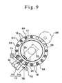
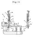
- Figs. 10 and 11 illustrate a principal portion of a conventional non-contact type inspection system 2 wherein test samples are ampoules 1.
- the ampoules 1 are conveyed while being put on seats 3a formed on a rotary table 3.
- a table 8 is disposed inside the rotary table 3 which conveys the ampoules 1, while a table 8a is disposed outside the rotary table 3.
- Light is emitted from an electric light 4 disposed on the inner table 8 and is passed through each ampoule 1 from the back side of the ampoule 1, then is photographed by a CCD camera 5 disposed on the outer table 8a.
- the inspection system 2 is provided with caps 6 whereby the ampoules 1 being conveyed with rotation of the rotary table 3 are pressed from above and are thereby held stably.
- the caps 6 are attached a large number to the upper portion of a cylindrical drum 7 in the circumferential direction of the drum 7.
- the drum 7, which is mounted on the rotary table 3 integrally, is rotated together with the rotary table 3 so that the caps 6 can move rotatively together with the ampoules 1 which are moved rotatively.
- the caps 6 can move vertically through sliding rods 6a to receive and subsequently hold the ampoules 1.
- the drum 7, which is mounted on the rotary table 3 for co-rotation with the same table 3, has a cylindrical wall 7a, and this cylindrical wall 7a, located behind the ampoules 1, shields the ampoules 1 from the electric light 4. Therefore, for causing the light from the electric light 4 to pass through the ampoules 1 in the inspection work, slits 9 are formed in the cylindrical wall 7a in positions corresponding to the positions of the caps 6, allowing the light from the electric light 4 to be radiated to the backs of the ampoules 1.
- US-A-4241256 discloses an apparatus for detecting foreign matters in liquids. Containers are fed onto a transferring board which moves continuously at a fixed speed. An optical detector then moves in synchronism to illuminate the container and detect foreign matters.
- EP-A-0585821 discloses a container inspecting apparatus in which containers are movable along a circular path in a plurality of feed units. The containers are stopped at fixed inspecting positions and a plurality of inspecting devices inspect the containers.
- the present invention has been accomplished in view of the above-mentioned problem of the prior art and it is an object of the invention to provide a non-contact type inspection system capable of allowing non-contact type inspection devices to exhibit their inspection ability to a satisfactory extent, permitting a more free layout of the inspection devices, and capable of inspecting test samples with a high accuracy and over a wide range, using the inspection devices.
- the non-contact type inspection system of the present invention comprises an annular rotary table which is rotated to convey test samples, an inspection device mounting table disposed inside and outside the rotary table in a sandwiching relation to said rotary table, said inspection device mounting table being pivotally rotatable with the rotation of said rotary table around a rotation center of said rotary table, and having a non-contact type inspection device mounted on said inspection device mounting table for inspection of said test samples passing through said inspection system by conveyance on said rotary table; a rotary head which is supported above said rotary table and rotatably about the rotation center of said rotary table to hold the upper portions of said test samples being conveyed by said rotary table; and an interlocking mechanism for rotating said rotary head in synchronism with said rotary table, whereby said inspection system further comprises: a rotation input shaft which is driven rotatively, and having a continuous rotation drive cam and a pivotal rotation drive cam being coaxially mounted on said rotation input shaft side by side;
- the rotary head is supported vertically movably.
- the interlocking mechanism includes a planetary gear mechanism which comprises a pair of first and second internal gears formed in the rotary table and the rotary head, respectively, a pair of first and second planetary gears meshing with the first and second internal gears, respectively, and a connecting shaft supported by the inspection device mounting table to connect the first and second planetary gears integrally with each other.
- a planetary gear mechanism which comprises a pair of first and second internal gears formed in the rotary table and the rotary head, respectively, a pair of first and second planetary gears meshing with the first and second internal gears, respectively, and a connecting shaft supported by the inspection device mounting table to connect the first and second planetary gears integrally with each other.
- the first and second internal gears have the same module and are integrally formed on the inner periphery of the rotary table and the inner periphery of the rotary head, respectively, the first and second planetary gears also have the same module, and the connecting shaft for connection of both planetary gears is supported rotatably by a bearing member provided on the inspection device mounting table.
- the rotary head is supported vertically movably and the second planetary gear meshing with the second internal gear in the rotary head is formed axially long in proportion to the vertical displacement of the rotary head.
- the non-contact type inspection system further includes a holding frame disposed above the rotary table and formed with a vertically extending slide groove, an annular lift frame mounted to the holding frame vertically movably through the slide groove, and a bearing provided on the inner periphery of the lift frame to support the outer periphery of the rotary head rotatably, wherein the rotary head being suspended from the holding frame vertically movably and rotatably through the lift frame.
- the non-contact type inspection system further includes the lift frame which is mounted to the holding frame vertically movably through the slide groove, bolts supported rotatably by the holding frame and screwed to be engaged with the lift frame, and a power transfer mechanism comprising sprockets mounted on the bolts and a chain entrained on the sprockets for the transfer of a driving force.
- the rotary table is provided with an input gear
- an output gear is provided on the continuous rotation output shaft and is in mesh with the input gear
- the turret associated with the continuous rotation output shaft is circular and is mounted on the continuous rotation output shaft
- cam followers are provided rotatably on the outer periphery of the circular turret so as to come into sliding contact with the continuous rotation drive cam.
- a support shaft is provided at a rotation center position of the inspection device mounting table, the pivotal rotation output shaft is connected to the support shaft, the turret associated with the pivotal rotation output shaft is sectorial and is mounted on the pivotal rotation output shaft, and cam followers are provided rotatably on the outer periphery of the sectorial turret so as to come into sliding contact with the pivotal rotation drive cam.
- the continuous rotation drive cam and the pivotal rotation drive cam which determine the rotating speed of the rotary table and that of the inspection device mounting table, have cam curves designed such that at a timing at which the inspection device mounting table rotates in the same direction as the rotating direction of the rotary table, the rotating speed of the inspection device mounting table and that of the rotary table are equal to each other, while at a timing at which the inspection device mounting table rotates in the direction opposite to the rotating direction of the rotary table, the rotating speed of the inspection device mounting table is higher than that of the rotary table.
- the rotary table is formed in an annular shape
- the inspection device mounting table comprises an inner table disposed in a space inside the rotary table and an outer table disposed in a space outside the rotary table in an opposed relation to the inner table
- a support shaft is integrally provided at a rotation center position of the inner table
- an arm extending to the outside of the rotary table is integrally provided on the support shaft
- the outer table is integrally mounted to the arm.
- the non-contact type inspection device is disposed on each of the inner table and the outer table in an opposed relation with the rotary table and the test samples being conveyed are located therebetween.
- the non-contact type inspection device comprises a projector for radiating light to be reflected by each of the test samples and a CCD camera for photographing each of the test samples to obtain an image thereof, the projector and the CCD camera being disposed on the inner table and the outer table, respectively, an image of the reflection reflected by the test sample by the light radiated from the projector is photographed by the CCD camera and the test sample is inspected on the basis of the image thereof thus obtained.
- the non-contact type inspection device comprises a backlight for radiating light to pass through each of the test samples and a transmission type sensor for sensing the thus-transmitted light, the backlight and the transmission type sensor being disposed on the inner table and the outer table, respectively, and the transmitted light through each test sample after radiation from the backlight is sensed by the transmission type sensor to inspect the test sample.
- the non-contact type inspection device utilizes X-rays and/or an electromagnetic wave.
- the rotary head is provided with stems inserted therein vertically slidably and springs for urging the stems downward, and caps for holding the upper portions of the test samples are provided respectively at the lower ends of the stems.
- a feed line for feeding the test samples onto the rotary table and a discharge line for discharging the test samples from the rotary table are disposed around the rotary table spaced apart from each other in the circumferential direction of the rotary table.
- the rotary head is supported above the rotary table so as to be rotatable about the rotation center of the rotary table.
- the rotary head is rotated in synchronism with the rotary table by means of the interlocking mechanism. Consequently, when test samples are conveyed by the rotary table, their upper portions are held by the rotary head rotating in synchronism with the rotary table.
- test samples being conveyed by both of the rotary table and the rotary head pass through the inspection device mounting table portions disposed respectively inside and outside the annular rotary table, they are each inspected by non-contact type inspection devices mounted on the said table portions.
- the space above the rotary table which is also the space above the test samples, is a dead space including no obstacle in the system structure, and the rotary head is supported in this dead space.
- the test sample holding position by the rotary head varies up and down, that is, it becomes possible to inspect plural test samples of different heights using a single inspection system.
- the interlocking mechanism comprises a pair of first and second internal gears provided on the rotary table and the rotary head, respectively, a pair of first and second planetary gears meshing with the first and second internal gears, respectively, and a connecting shaft supported rotatably by the inspection device mounting table to connect the first and second planetary gears integrally with each other.
- first and second planetary gears are supported by the inspection device mounting table, even if the inspection device mounting table is a fixed type or even if it is a rotary type table which is relatively rotated as necessary with respect to the rotary table, it is possible to let the first and second internal gears rotate at an equal speed, so that the rotary table and the rotary head are rotated always synchronously.
- the rotary table when the rotation input shaft is rotated to rotate both continuous rotation drive cam and pivotal rotation drive cam, the rotary table is rotated continuously by the former continuous rotation drive cam via the turret and the continuous rotation output shaft and the inspection device mounting table is pivotally rotated to and fro in a same direction as and opposite to the rotating direction of the rotary table via the turret and the pivotal rotation outer shaft.
- the rotary table which rotates continuously conveys the test samples continuously.
- the inspection device mounting table when it is rotated in the same direction as the rotating direction of the rotary table, is rotated in synchronism with the rotary table.
- the non-contact type inspection device mounted on the inspection device mounting table is moved together and synchronously with the test samples being conveyed by the rotary table.
- This synchronous rotation of both tables permits the non-contact type inspection device to inspect the test samples, whereby there can be created a state as if still test samples are inspected by a still inspection device.
- the test samples can be conveyed continuously by the rotary table.
- the inspection device mounting table is rotated in the direction opposite to the rotating direction of the rotary table to return its original position, for the next inspection work.
- the continuous rotation of the rotary table and the pivotal rotation of the inspection device mounting table can be obtained by the use of the continuous rotation drive cam and the pivotal rotation drive cam, respectively.
- the application of cams above described since there is no backlash in a series of motion transfer, always realizes the accurate operation and enhances the accuracy of rotational motion of the tables.
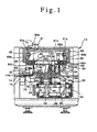
- FIG. 1 to 9 illustrate one embodiment of a non-contact type inspection system according to the present invention.
- a non-contact type inspection system 10 embodying the present invention comprises an annular rotary table 12 which has a circular opening formed inside and which is driven rotatively, an inner table 14a disposed inside the rotary table 12 so as to be rotatable about the rotation center of the rotary table 12, and an outer table 14b disposed outside the rotary table 12 so as to be rotatable about the rotation center of the rotary table 12.
- An inspection device mounting table 14 is constituted by the inner table 14a and the outer table 14b.
- the rotary table 12 is adapted to place products 18 to be inspected as test samples thereon and convey them.
- the products 18 are received onto the rotary table 12 from a feed line 16, the rotary table 12 rotates with the products 18 carried thereon, and the products 18 after inspected are discharged through a discharge line 20.
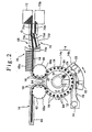
- the inner table 14a is formed in the shape of a disk, and a support shaft 22 is integrally attached at the under side of the central part of the inner table 14a, as shown in Figs. 1 and 2.
- the outer table 14b is formed in the shape of an arcuate belt exceeding about one sixth of the circumference of the rotary table 12, and a sectorial arm 24 is integrally projected from the underside of the outer table 14b.
- a pivot portion of the sectorial arm 24 is integrally fitted on the lower portion of the support shaft 22 of the inner table 14a, whereby the inner and outer tables 14a and 14b are rendered integral with each other.
- a boss portion 26 is integrally formed on the lower surface of the rotary table 12 and it is fitted on the upper portion of the support shaft 22 rotatably through bearings 28.
- a projector 30 and a transmission type sensor 31 are mounted on the inner table 14a, while a CCD camera 32 and a backlight 33 are mounted on the outer table 14b.
- the projector 30 and the CCD camera 32, as well as the transmission type sensor 31 and the backlight 33, as non-contact type inspection devices to inspect the products 18 to be inspected, are disposed opposedly to each other in a sandwiching relation to the products 18 which are conveyed by the rotary table 12.
- the cam mechanism 36 for driving both tables 12 and 14.
- the cam mechanism 36 is provided with a rotation input shaft 38 to which is inputted a rotating force from a rotative drive source (not shown).
- a continuous rotation drive cam 40 and a pivotal rotation drive cam 42 are coaxially mounted on the rotation input shaft 38 spaced apart each other.
- a continuous rotation output shaft 44 and a pivotal rotation output shaft 46 are disposed sideways of the continuous rotation drive cam 40 and the pivotal rotation drive cam 42. These output shafts 44 and 46 are arranged perpendicularly to the rotation input shaft 38.
- a circular turret 48 is fitted on the continuous rotation output shaft 44, and cam followers 50 are provided rotatably on the outer periphery of the turret 48 so as to come into sliding contact with the continuous rotation drive cam 40.
- a sectorial turret 52 is fitted on the pivotal rotation output shaft 46, and cam followers 54 are provided rotatably on the outer periphery of the turret 52 so as to come into sliding contact with the pivotal rotation drive cam 42.
- An output gear 56 is fixed to the upper end of the continuous rotation output shaft 44, while an input gear 58 is fixed to the lower end of the boss portion 26 of the rotary table 12.
- the output gear 56 and the input gear 58 are meshed with each other, whereby the rotation of the continuous rotation output shaft 44 is transmitted to the rotary table 12, so that the rotary table 12 is rotated continuously.
- the upper end of the pivotal rotation output shaft 46 is integrally connected to the lower end of the support shaft 22 of the inner table 14a, whereby the pivotal rotation of the pivotal rotation output shaft 46 is transmitted to the support shaft 22 to pivotally rotate the inspection device mounting table 14 which comprises the inner table 14a and the outer table 14b.
- the inspection device mounting table 14 at its advance path, is rotated in the same direction as the rotating direction of the rotary table 12, and subsequently at its return path, is rotated in the direction opposite to the rotating direction of the rotary table 12.
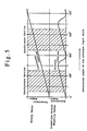
- the cam surface of the pivotal rotation drive cam 42 which causes the inspection device mounting table 14 to reciprocate pivotally is designed such that at the advance path of the inspection device mounting table 14, the rotating speed of the table 14 is equal to that of the rotary table 12 to synchronize the rotational motions of these tables 12 and 14, while at its return path the rotating speed of the table 14 is higher than that of its advanced path to permits the table 14 to return its original position quickly.
- the motional relation between the rotary table 12 and the inspection device mounting table 14 is shown in terms of a time chart in Fig. 5. In the hatched areas in the same figure, both tables 12 and 14 are rendered equal to each other in the inclination of rotational angle (rotating speed) so that the tables 12 and 14 are rotated at the same speed synchronously in the same direction.
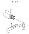
- the CCD camera 32 mounted on the inspection device mounting table 14, as shown in Fig. 7, for example, by combining the CCD camera 32 with the projector 30, the light beams irradiated by the projector 30 are reflected by the products 18 and the CCD camera 32 photographs the reflected light.
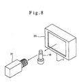
- the products 18 are transparent vessels containing liquids such as ampoules, vials or the like, as shown in Fig. 8, by combining the transmission type sensor 31 and the backlight 33, the light beams irradiated by the backlight 33 are permitted to pass through the products 18, and the transmitted light is sensed by the transmission type sensor 31.
- the image photographed by the CCD camera 32 is sent to an image processor.
- the signals sensed by the transmission type sensor 31 are transmitted to a processor. And then, the appearance of the products 18 is inspected and foreign materials mixed to the contents thereof are detected if any to judge whether the products 18 are acceptable or not acceptable.
- the feed line 16 for feeding the products 18 to be inspected onto the rotary table 12 is provided with a guide 60 for moving the products 18 in a row and in an orderly manner and a first star wheel 62 disposed at an outlet portion of the guide 60, as shown in Fig. 2.
- the products 18 are pushed out successively from the guide 60 and are received one by one in recesses 62a formed at equal intervals in the outer periphery of the first star wheel 62.
- the first star wheel 62 rotates to put the products 18 onto rotatable seats 64 successively one by one.
- the rotatable seats 64 are formed on the rotary table 12 to let the products 18 rotate on their own axes.
- the discharge line 20 for discharging the products 18 to be inspected from the rotary table 12 after finishing the inspection is composed of a second star wheel 66 and a sorter 68 contiguous to the second star wheel 66.
- the products 18 delivered successively from the rotary table 12 are received one by one into recesses 66a which are formed at equal intervals in the outer periphery of the second star wheel 66.
- the second star wheel 66 rotates in this state to deliver the products 18 one by one to the sorter 68.
- the sorter 68 is provided with a screw 68a for the conveyance of the products 18 which are delivered from the second star wheel 66, and a pendulum type sorting mechanism 70 for distributing the products 18 to be inspected, which are sent out one by one from the screw 68a, to a first sorting passage 70a or to a second sorting passage 70b.
- the pendulum type sorter 70 has a pendulum 70f.
- the pendulum 70f is provided so that it can reciprocate pivotally about its pivotal center O.
- the pendulum 70f has a pair of passages 70c and 70d bifurcately with respect to the pivotal center O.
- An inlet 70e is brought into communication with the first sorting passage 70a through a passage 70c or with the second sorting passage 70b through a passage 70d, alternatively in accordance a pivotal motion of the pendulum 70f centered at the pivotal center O.
- the products 18 conducted to the first sorting passage 70a are received in a first storage portion 72, while the products 18 conducted to the second sorting passage 70b are received in the second storage portion 72a.
- the first storage portion 72 is used for the storage of non-defective products
- the second storage portion 72a is used for the storage of defective products.
- spin shafts 64a suspended from the rotatable seats 64 to rotatably place the products 18 to be inspected are rotatably mounted on the rotary table 12 and are projected from the lower surface of the rotary table 12.
- the associated spin shaft 64a comes into sliding contact with a belt 78 which is entrained on and between a motor 74 and a pulley 76 and is driven in a circulative manner.
- the spin shaft 64a rotates and causes the rotatable seat 64 to rotate, so that the product 18 thereon is rotated on its own axis.
- each product 18 on the rotary table 12 By such rotation of each product 18 on the rotary table 12, the whole of its outer periphery can be photographed by a single CCD camera 32 and sensing work is conducted by the transmission type sensor 31.
- the products 18 are, for example, ampoules or vials and the contents thereof are to be checked with transmitted light, if each product 18 which has thus been rotated on its own axis is stopped suddenly, only the contents thereof continue to rotate therein and hence it is possible to check more exactly whether a foreign matter is fixed therein or not.
- the products 18 to be inspected which move with rotation of the rotary table 12 are held down at the respective upper portions by caps 82 secured to a rotary head 80.
- the non-contact type inspection system 10 is mounted to a frame 84 which surrounds the whole of the inspection system 10. In the top space of the frame 84 which space is a dead space causing no obstacle to the operation of the inspection system 10, the rotary head 80 is supported in a suspended state.
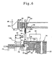
- the rotary head 80 is supported above the rotary table 12 and rotatably about the rotation center of the same table 12. At the peripheral edge portion of the rotary head 80 are provided the caps 82 in corresponding relation to the rotatable seats 64 formed on the rotary table 12. As shown in Fig. 6, the caps 82 are respectively formed at the lower ends of stems 82a which are inserted into the rotary head 80 vertically slidably. The stems 82a are pressed downward through springs 82b.
- the outer peripheral portion of the rotary head 80 is attached to the inner periphery of an annular lift frame 86 rotatably through bearings 86a.
- the lift frame 86 is mounted to the underside of the top portion of the frame 84 through a holding frame 88.
- the lift frame 86 is fitted vertically slidably in slide grooves 88a formed in the holding frame 88, and a plurality of bolts 90, which are rotatably fitted in the holding frame 88, are screwed into the lift frame 86.
- One of the bolts 90 is projected above the frame 84 and a handle 90a is provided at the upper end of the thus-projected bolt 90.
- a transmission mechanism 91 comprising sprockets 91a and a chain 91b, whereby all the bolts 90 are interlocked together.
- the lift frame 86 moves vertically together with the rotary head 80.
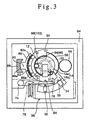
- an interlocking mechanism 92 is disposed between the rotary table 12 and the rotary head 80 to rotate the rotary head 80 in interlock with the rotary table 12.
- the interlocking mechanism 92 is constituted by connecting first and second internal gears 94 and 96 with each other through first and second planetary gears 98 and 100 meshing with the first and second internal gears 94 and 96 respectively, the first and second internal gears 94 and 96 being formed in the rotary table 12 and the rotary head 80, respectively.
- the first and second internal gears 94 and 96 are formed to have the same diameter.
- the first internal gear 94 is integrally formed in the inner periphery of the rotary table 12, while the second internal gear 96 is integrally formed in the inner periphery of the rotary head 80.
- the first and second planetary gears 98 and 100 are also formed at the same diameter and are positioned outside a pivotal reciprocation range of the outer table 14b which is pivotally rotated by the pivotal rotation drive cam 42 to prevent the gears 98 and 100 from interfering the motion of the table 14, as shown in Fig. 3.
- the first and second planetary gears 98 and 100 are integrally connected together through a connecting shaft 102, and the connecting shaft 102 is supported rotatably by a bearing member 104 fixed to the inner table 14a.
- the second planetary gear 100 is formed axially long, taking the amount of vertical displacement of the rotary head 80 into account.
- the rotary table 12 is rotated continuously by the rotation of the continuous rotation drive cam 40 via the turret 48 and the continuous rotation output shaft 44, and the inspection device mounting table 14 is pivotally rotated to and fro pivotally by the pivotal rotation drive cam 42 via the turret 52 and the pivotal rotation output shaft 46 in directions same as and opposite to the rotating direction of the rotary table 12.
- the products 18 to be inspected are received onto the rotatable seats 64 on the rotary table 12 successively one by one from the feed line 16 and are conveyed continuously by the rotary table 12 which rotates continuously. This conveyance of the products 18 is effected stably because the upper portions of the products 18 on the rotary table 12 are held by the caps 82 of the rotary head 80.
- the inspection device mounting table 14 is rotated in the same direction as the rotating direction of the rotary table 12 in synchronism with the rotary table 12, so that the projector 30, the transmission type sensor 31, the CCD camera 32 and the backlight 33, which are mounted on the inspection device mounting table 14, move integrally and synchronously with the products 18 to be inspected being conveyed by the rotary table 12.
- the products 18 are inspected by the non-contact type inspection devices, including the CCD camera 32, whereby there can be created a state as if still products 18 were inspected by still inspection devices, and thus the inspection can be effected with a high accuracy.
- the inspection system of this embodiment permits a high-accuracy inspection of pin-holes of glass and fine cracks and the like.
- the products 18 to be inspected are not limited to those referred to above, but various other products, including electronic components, may be used as the products 18.
- the products 18 can be conveyed by the rotary table 12 without interruption, thus ensuring a high productivity.
- the inspection device mounting table 14 is rotated promptly in the direction opposite to the rotating direction of the rotary table 12 to return its original position, and is now ready for the next inspection work.
- the products 18 to be inspected having been inspected on the rotary table 12 are sent out to the discharge line 20, then non-defective products pass the screw 68a of the sorter 68 and are thereafter received into the first storage portion 72 through the passage 70c and the first sorting passage 70a by means of the illustrated pendulum 70f.
- the pendulum 70f is moved pivotally to store the defective product into the second storage portion 72a through the passage 70d and the second sorting passage 70b.
- the light rays radiated from the projector 30 and backlight 33 are utilized to check the products 18 to be inspected, this constitutes no limitation, but such inspection devices may be substituted by inspection devices which utilize, for example, X-rays or an electromagnetic wave.
- the rotary head 80 having caps 82 for holding the upper portions of the products 18 to be inspected is supported above the rotary table 12 in a suspended state from the top portion of the frame 84 through both holding frame 88 and lift frame 86, an open space including no obstacle can be formed throughout the whole circumference of both rotary table 12 and rotary head 80 above the rotary table 12 and below the rotary head 80.
- non-contact type inspection devices as the projector 30, the transmission type sensor 31, the CCD camera 32 and the backlight 33, there is no obstruction between those inspection devices arranged in a sandwiching relation to the rotary table 12 and the products 18 carried on the rotary table 12. Consequently, the inspection ability of the inspection devices can be exhibited to a satisfactory extent, the layout of the inspection devices for the products 18 can be set freely, and the inspection of the products 18 by the inspection devices can be conducted with a high accuracy and over a wide range.
- the lift frame 86 which holds the rotary head 80 rotatably, is mounted to the holding frame 88 fixed to the frame 84, in a vertically movable manner through bolts 90.
- the rotary head 80 is moved vertically by operation of the handle 90a.
- the rotary head 80 which is supported in a suspended state from the top of the frame 84, is interlocked with the rotary table 12 by means of the interlocking mechanism 92.
- the interlocking mechanism 92 is composed of first and second internal gears 94 and 96 formed in the rotary table 12 and the rotary head 80, respectively, and a pair of first and second interconnected planetary gears 98 and 100 meshing with the first and second internal gears 94 and 96, respectively.
- the first and second planetary gears 98 and 100 are supported by the inspection device mounting table 14.
- the first and second planetary gears 98 and 100 are supported by the inspection device mounting table 14 through the bearing member 104, even if the table 14 relatively rotates with respect to the rotary table 12, the first and second internal gears 94 and 96 can be rotated at an equal speed and hence both rotary table 12 and rotary head 80 can be rotated synchronously at all times.
- the first and second planetary gears 98 and 100 do not rotate.
- the interlocking mechanism 92 is used, it does not occur any vibration caused by the application of the interlocking mechanism 92. That is, the inspection can be carried out in a vibration-free state and an extremely high accuracy of inspection work can be ensured.
- the rotation of the rotation input shaft 38 is converted into the continuous rotation of the rotary table 12 and the pivotal rotation of the inspection device mounting table 14.
- the rotary table 12 with the positioning grooves and holes or the like for the products 18 to be inspected on the surface thereof, the positioning accuracy of the products 18 is enhanced and it is possible to eliminate the blur of image and falling out of focus.
- it can be allowed to mount the CCD camera 32 and the transmission type sensor 31 on the inspection device mounting table 14 in the direction desired to be inspected, which makes it possible to perform a number of items of inspections at one time.
- the non-contact type inspection system in the first aspect of the present invention since the rotary head which holds the upper portions of test samples to be inspected is supported above the rotary table, an open space free of any obstacle can be formed throughout the whole circumference of both rotary table and rotary head above the rotary table and below the rotary head.
- the inspection ability of the inspection devices can be exhibited to a satisfactory extent, the layout of the inspection devices for test samples can be designed freely, and thus the inspection of test samples by the inspection devices can be performed with a high accuracy and over a wide range.
- the rotary head is supported in the space above the rotary table which space is a dead space located above the test sample conveying path and including no obstacle in the system construction, it is not necessary to ensure any special space for mounting of the rotary head.
- An appropriate layout of the rotary head can be realized by effectively utilizing such dead space.
- the test sample holding position by the rotary head can be varied up and down, whereby plural test samples of different heights can be inspected using a single inspection system.
- the interlocking mechanism comprises a pair of first and second internal gears formed in the rotary table and the rotary head, respectively, a pair of first and second planetary gears meshing with the first and second internal gears, respectively, and a connecting shaft supported by the inspection device mounting table to connect the first and second planetary gears integrally with each other. Accordingly, when the first internal gear is rotated together with the rotary table, the first planetary gear meshing with the first internal gear and the second planetary gear connected to the first planetary gear rotate, and the second internal gear meshing with the second planetary gear also rotates. In this way the rotary head can be rotated in synchronism with the rotary table.
- the first and second internal gears can be rotated at an equal speed, and the rotary table and the rotary head can be rotated synchronously at all times, irrespective of whether the inspection device mounting table is a fixed type or a rotatable type which is relatively rotated as necessary with respect to the rotary table.
- the rotation input shaft is rotated to rotate the continuous rotation drive cam and the pivotal rotation drive cam
- the rotary table is rotated continuously via the turret and the continuous rotation output shaft
- the inspection device mounting table is rotated continuously to rotate pivotally via the turret and the pivotal rotation output shaft.
- test samples is conveyed continuously by the rotary table being rotating continuously.
- the inspection device mounting table is rotated in synchronism with the rotary table when it is rotated in the same direction as the rotating direction of the rotary table
- the non-contact type inspection device mounted on the inspection device mounting table is moved together in synchronism with the test samples conveyed by the rotary table.
- the test samples can be inspected by the non-contact type inspection device, whereby there can be realized the state as if the still test samples are inspected by the still inspection device, so that the inspection can be effected with high accuracy.
- test samples can be conveyed by the rotary table without interruption, thus ensuring a high productivity.
- the continuous rotation of the rotary table and the pivotal rotation of the inspection device mounting table can be obtained by the use of the continuous rotation drive cam and the pivotal rotation drive cam. Accordingly, there is no backlash in a series of motion transfer, accurate operation can be realized continuously and the accurate rotational motion of the tables can be realized.
- the present invention exhibits the effects of enhancing the inspection accuracy in the inspection work liable to be effected by the accuracy of the rotational motion of the tables.
Landscapes
- General Health & Medical Sciences (AREA)
- Physics & Mathematics (AREA)
- Life Sciences & Earth Sciences (AREA)
- Chemical & Material Sciences (AREA)
- Analytical Chemistry (AREA)
- Biochemistry (AREA)
- Immunology (AREA)
- General Physics & Mathematics (AREA)
- Health & Medical Sciences (AREA)
- Pathology (AREA)
- Investigating Materials By The Use Of Optical Means Adapted For Particular Applications (AREA)
- Analysing Materials By The Use Of Radiation (AREA)
- Sampling And Sample Adjustment (AREA)
- Specific Conveyance Elements (AREA)
Claims (17)
- Berührungsloses Prüfsystem (10) mit
einem ringförmigen Drehtisch (12), der gedreht wird, um Messproben (18) zu befördern;
einem Prüfgeräte-Montagetisch (14), der innerhalb und außerhalb des Drehtisches (12) in einer Sandwichbeziehung zu dem. Drehtisch (12) angeordnet ist,
wobei der Prüfgeräte-Montagetisch (14) mit der Drehung des Drehtisches (12) um eine Drehachse des Drehtisches (12) drehbar ist und ein auf dem Prüfgeräte-Montagetisch (12) montiertes berührungsloses Prüfgerät (30, 32) zur Prüfung der durch das Prüfsystem (12) durch Beförderung auf dem Drehtisch (12) gelangende Messproben aufweist:dadurch gekennzeichnet, dass das Prüfsystem weiter aufweist:einem Drehkopf (80), der über dem Drehtisch (12) gehalten und um die Drehachse des Drehtisches (12) drehbar ist, um die oberen Abschnitte der durch den Drehtisch (12) beförderten Messproben (18) zu halten; undeinem Verriegelungsmechanismus (92), der angeordnet ist, um den Drehkopf (80) synchron mit dem Drehtisch (12) zu drehen,wobei der erste und der zweite Drehantriebsnocken (40, 42) und die ersten und die zweiten Nockenstößel (50, 54) so ausgerichtet sind, dass der Drehtisch (12) kontinuierlich durch die erste Drehausgangswelle (44) gedreht wird, der Prüfgeräte-Montagetisch (14) durch die zweite Drehausgangswelle (46) vor und zurück gedreht wird, und, wenn der Prüfgerät-Montagetisch (14) in die gleiche Richtung wie die Drehrichtung des Drehtisches (12) gedreht wird, der Prüfgeräte-Montagetisch (14) synchron zu dem Drehtisch (12) gedreht wird.eine Drehantriebswelle (38), die drehbar angetrieben ist und die einen ersten Drehantriebsnocken (40) und einen zweiten Drehantriebsnocken (42) aufweist, welche koaxial nebeneinander auf der Drehantriebswelle (38) montiert sind;eine erste Drehausgangswelle (44), welche im Wesentlichen senkrecht bezüglich der Drehantriebswelle (38) ausgerichtet ist und durch einen ersten Revolverkopf (48) kontinuierlich gedreht wird, wobei der erste Revolverkopf (48) erste Nockenstößel (50) aufweist, die mit dem ersten Drehantriebsnocken (40) in Gleitkontakt stehen; undeine zweite Drehausgangswelle (46), welche im Wesentlichen senkrecht bezüglich der Drehantriebswelle (38) ausgerichtet ist und durch einen zweiten Revolverkopf (52) gedreht wird, wobei der zweite Revolverkopf (52) zweite Nockenstößel (54) aufweist, die in Gleitkontakt mit dem zweiten Drehantriebsnocken (42) stehen; - Berührungsloses Prüfsystem nach Anspruch 1, bei welchem der Drehkopf (80) vertikal bewegbar gehalten ist.
- Berührungsloses Prüfsystem nach Anspruch 1, bei welchem der Verriegelungsmechanismus (92) einen Planetengetriebemechanismus enthält, welcher aufweist:ein Paar einer ersten und einer zweiten Innenverzahnung (94, 96), welche in dem Drehtisch (12) bzw. dem Drehkopf (80) ausgebildet sind;ein Paar eines ersten und eines zweiten Planetengetriebes (98, 100), welche mit der ersten bzw. der zweiten Innenverzahnung (94, 96) in Eingriff stehen; undeine Verbindungswelle (102), die durch den Prüfgeräte-Montagetisch (14) gehalten ist, um das erste und das zweite Planetengetriebe (98, 100) integral miteinander zu verbinden.
- Berührungsloses Prüfsystem nach Anspruch 3, bei welchem die erste und die zweite Innenverzahnung (94, 96) das gleiche Modul besitzen und integral an dem Innenumfang des Drehtisches (12) bzw. dem Innenumfang des Drehkopfes (80) gebildet sind, das erste und das zweite Planetengetriebe (98, 100) ebenso das gleiche Modul besitzen, und die Verbindungswelle (102) zur Verbindung beider Planetengetriebe (98, 100) drehbar durch ein an dem Prüfgeräte-Montagetisch (14) vorgesehenes Lagerelement (104) gehalten ist.
- Berührungsloses Prüfsystem nach Anspruch 3, bei welchem der Drehkopf (80) vertikal bewegbar gehalten ist und das mit der zweiten Innenverzahnung (96) in dem Drehkopf (80) in Eingriff stehende zweite Planetengetriebe (100) im Verhältnis zu dem vertikalen Weg des Drehkopfes (80) axial lang ausgebildet ist.
- Berührungsloses Prüfsystem nach Anspruch 2, ferner mit
einem Halterahmen (88), der über dem Drehtisch (12) angeordnet und mit einer sich vertikal erstreckenden Gleitnut (88a) ausgebildet ist;
einem ringförmigen Hubrahmen (86), der vertikal bewegbar durch die Gleitnut (88a) an dem Halterahmen (88) befestigt ist; und
einem Lager (86a), das an dem Innenumfang des Hubrahmens (86) vorgesehen ist, um den Außenumfang des Drehkopfes (80) drehbar zu halten,
wobei der Drehkopf (80) von dem Halterahmen (88) durch den Hubrahmen (86) vertikal bewegbar und drehbar abgehängt ist. - Berührungsloses Prüfsystem nach Anspruch 6, ferner mit
Schrauben (90), die drehbar durch den Halterahmen (88) gehalten und in Eingriff mit dem Hubrahmen (86) geschraubt sind; und
einem Kraftübertragungsmechanismus (91) mit an den Schrauben (90) befestigten Zahnrollen (91a) und einer an den Zahnrollen (91a) geführten Kette (91b) für die Übertragung einer Antriebskraft. - Berührungsloses Prüfsystem nach Anspruch 1, bei welchem der Drehtisch (12) mit einem Eingangsgetriebe (58) versehen ist, ein Ausgangsgetriebe (56) an der ersten Drehausgangswelle (44) vorgesehen ist und mit der Eingangswelle (58) in Eingriff steht, der der ersten Drehausgangswelle (44) zugeordnete erste Revolverkopf (48) kreisförmig ist und an der ersten Drehausgangswelle (44) befestigt ist, und die ersten Nockenstößel (50) drehbar an dem Außenumfang des ersten Revolverkopfes (48) vorgesehen sind, um so mit dem ersten Drehantriebsnocken (40) in Gleitkontakt zu kommen.
- Berührungsloses Prüfsystem nach Anspruch 1, bei welchem eine Haltewelle (22) an einer Drehachsenposition des Prüfgeräte-Montagetisches (14) vorgesehen ist, die zweite Drehausgangswelle (46) mit der Haltewelle (22) verbunden ist, der der zweiten Drehausgangswelle (46) zugeordnete zweite Revolverkopf (52) sektorförmig ist und an der zweiten Drehausgangswelle (46) befestigt ist, und die zweiten Nockenstößel (54) drehbar an dem Außenumfang des zweiten Revolverkopfes (52) vorgesehen sind, um so mit dem zweiten Drehantriebsnocken (42) in Gleitkontakt zu kommen.
- Berührungsloses Prüfsystem nach Anspruch 1, bei welchem der erste Drehantriebsnocken (40) und der zweite Drehantriebsnocken (42), welche die Drehgeschwindigkeit des Drehtisches (12) und jene des Prüfgeräte-Montagetisches (14) bestimmen, Nockenkurven besitzen, die so konstruiert sind, dass zu einem Takt, bei welchem der Prüfgeräte-Montagetisch (14) in die gleiche Richtung wie die Drehrichtung des Drehtisches (12) dreht, die Drehgeschwindigkeit des Prüfgeräte-Montagetisches (14) und jene des Drehtisches (12) zueinander gleich sind, während zu einem Takt, bei welchem der Prüfgeräte-Montagetisch (14) in die Richtung entgegen der Drehrichtung des Drehtisches (12) dreht, die Drehgeschwindigkeit des Prüfgeräte-Montagetisches (14) höher als jene des Drehtisches (12) ist.
- Berührungsloses Prüfsystem nach Anspruch 1, bei welchem der Drehtisch (12) in einer Ringform gebildet ist, der Prüfgerät-Montagetisch (14) einen in einem Raum innerhalb des Drehtisches (12) angeordneten Innentisch (14a) und einen in einem Raum außerhalb des Drehtisches (12) in einer zu dem Innentisch (12) gegenüber liegenden Beziehung angeordneten Außentisch (14b) aufweist, eine Haltewelle (22) integral an einer Drehachsenposition des Innentisches (12) vorgesehen ist, ein sich zur Außenseite des Drehtisches (12) erstreckender Arm (24) integral an der Haltewelle (22) vorgesehen ist, und der Außentisch (14b) integral an dem Arm (24) befestigt ist.
- Berührungsloses Prüfsystem nach Anspruch 11, bei welchem das berührungslose Prüfgerät (30, 32) auf jedem des Innentisches (14a) und des Außentisches (14b) in einer gegenüber liegenden Beziehung zu dem Drehtisch (12) angeordnet ist und die beförderten Messproben (18) dazwischen positioniert sind.
- Berührungsloses Prüfsystem nach Anspruch 12, bei welchem das berührungslose Prüfgerät (30, 32) einen Projektor (30) zum Aussenden eines Lichts, um durch jede der Messproben (18) reflektiert zu werden, und eine CCD-Kamera (32) zum Photographieren jeder der Messproben (18), um ein Bild davon zu erhalten, aufweist, wobei der Projektor (30) und die CCD-Kamera (32) auf dem Innentisch (14a) bzw. dem Außentisch (14b) angeordnet sind, ein Bild der durch jede Messprobe (18) durch das von dem Projektor (30) ausgesendete Licht reflektierten Reflexion durch die CCD-Kamera (32) photographiert wird und die Messprobe (18) auf der Basis des so erhaltenen Bildes davon untersucht wird.
- Berührungsloses Prüfsystem nach Anspruch 12, bei welchem das berührungslose Prüfgerät (30, 32) ein Durchlicht (33) zum Aussenden von Licht, um durch jede der Messproben (18) zu laufen, und einen Durchlässigkeitssensor (31) zum Messen des so übertragenen Lichts aufweist, wobei das Durchlicht (33) und der Durchlässigkeitssensor (31) auf dem Innentisch (14a) bzw. dem Außentisch (14b) angeordnet sind und das übertragene Licht durch jede Messprobe (18) nach Aussenden von dem Durchlicht (33) durch den Durchlässigkeitssensor (31) gemessen wird, um die Messprobe (18) zu untersuchen.
- Berührungsloses Prüfsystem nach Anspruch 1, bei welchem das berührungslose Prüfgerät Röntgenstrahlen und eine elektromagnetische Welle verwendet.
- Berührungsloses Prüfsystem nach Anspruch 1, bei welchem der Drehkopf (80) mit vertikal verschiebbaren eingesetzten Stäben (82a) und Federn (82b) zum Drücken der Stäbe (82a) nach unten versehen ist und Kappen (82) zum Halten der oberen Abschnitte der Messproben (18) jeweils an den unteren Enden der Stäbe (82a) vorgesehen sind.
- Berührungsloses Prüfsystem nach Anspruch 1, bei welchem eine Zufuhrstrecke (16) zum Zuführen der Messproben (18) auf den Drehtisch (12) und eine Ausgabestrecke (20) zum Ausgeben der Proben (18) von dem Drehtisch (12) um den Drehtisch (12) voneinander in der Umfangsrichtung des Drehtisches (12) beabstandet angeordnet sind.
Priority Applications (1)
| Application Number | Priority Date | Filing Date | Title |
|---|---|---|---|
| DK97918351T DK0837311T3 (da) | 1996-05-02 | 1997-05-01 | Apparat til beröringsfri inspektion |
Applications Claiming Priority (4)
| Application Number | Priority Date | Filing Date | Title |
|---|---|---|---|
| JP111757/96 | 1996-05-02 | ||
| JP11175796 | 1996-05-02 | ||
| JP11175796 | 1996-05-02 | ||
| PCT/JP1997/001499 WO1997042480A1 (fr) | 1996-05-02 | 1997-05-01 | Dispositif d'inspection sans contact |
Publications (3)
| Publication Number | Publication Date |
|---|---|
| EP0837311A1 EP0837311A1 (de) | 1998-04-22 |
| EP0837311A4 EP0837311A4 (de) | 2001-02-07 |
| EP0837311B1 true EP0837311B1 (de) | 2004-07-21 |
Family
ID=14569424
Family Applications (1)
| Application Number | Title | Priority Date | Filing Date |
|---|---|---|---|
| EP97918351A Expired - Lifetime EP0837311B1 (de) | 1996-05-02 | 1997-05-01 | Vorrichtung zur kontaktlosen inspektion |
Country Status (9)
| Country | Link |
|---|---|
| US (1) | US6055876A (de) |
| EP (1) | EP0837311B1 (de) |
| JP (1) | JP3601933B2 (de) |
| KR (1) | KR19990028688A (de) |
| BR (1) | BR9702250A (de) |
| DE (1) | DE69729923T2 (de) |
| DK (1) | DK0837311T3 (de) |
| TW (1) | TW338104B (de) |
| WO (1) | WO1997042480A1 (de) |
Cited By (1)
| Publication number | Priority date | Publication date | Assignee | Title |
|---|---|---|---|---|
| DE102019211920B4 (de) * | 2019-08-08 | 2025-04-24 | Syntegon Technology Gmbh | Vorrichtung zum Drehen pharmazeutischer Behältnisse |
Families Citing this family (22)
| Publication number | Priority date | Publication date | Assignee | Title |
|---|---|---|---|---|
| JP4516201B2 (ja) * | 2000-11-01 | 2010-08-04 | リッカーマン(日本)株式会社 | 連続検査装置 |
| JP4696230B2 (ja) * | 2001-07-19 | 2011-06-08 | キリンテクノシステム株式会社 | 容器検査装置 |
| US7067323B2 (en) * | 2003-10-15 | 2006-06-27 | Lighthouse Instruments, Llc | System and method for automated headspace analysis |
| JP4587657B2 (ja) * | 2003-10-30 | 2010-11-24 | トヨタ自動車株式会社 | フェールセーフ油圧回路 |
| DE102004024277A1 (de) * | 2004-05-15 | 2005-12-01 | Sig Technology Ltd. | Verfahren und Vorrichtung zur Inspektion von Werkstücken |
| US7728873B2 (en) * | 2004-11-09 | 2010-06-01 | Cnoga Ltd | Apparatus for obtaining and electronically interpreting digital images of liquids, solids and combinations on liquids and solids |
| ITCR20070023A1 (it) * | 2007-09-11 | 2009-03-12 | Pharmamech Srl | Macchina ispezionatrice |
| JP5468467B2 (ja) * | 2010-02-08 | 2014-04-09 | 株式会社イシダ | X線検査装置 |
| JP2012068126A (ja) * | 2010-09-24 | 2012-04-05 | Ishida Co Ltd | X線検査装置 |
| IT1403497B1 (it) | 2010-12-27 | 2013-10-17 | Makro Labelling Srl | "dispositivo di rilevamento per contenitori in movimento" |
| CN106290159A (zh) * | 2011-01-21 | 2017-01-04 | 提拉诺斯公司 | 样品使用最大化的系统和方法 |
| CN103884721B (zh) * | 2012-12-20 | 2016-04-13 | 山东新华医疗器械股份有限公司 | 自动灯检机 |
| ITPR20130104A1 (it) * | 2013-12-20 | 2015-06-21 | One Love Di Tarasconi Ermina & C S A S | Sperlatrice e metodo di ispezione |
| DE102014216576A1 (de) * | 2014-08-21 | 2016-02-25 | Krones Ag | Behälterbehandlungsmaschine mit einer Inspektionsvorrichtung |
| KR101759242B1 (ko) | 2015-02-24 | 2017-07-18 | 정성화 | 폐전선 및 통신선 열분해장치 |
| KR101709343B1 (ko) * | 2015-07-28 | 2017-02-23 | 주식회사 완성 | 앰플 비전 검사 장치 및 검사 방법 |
| DE102017215927A1 (de) * | 2017-09-08 | 2019-03-14 | Krones Aktiengesellschaft | Vorrichtung zum Ausschleusen von in einer Direktdruckmaschine fehlerhaft bedruckten Behältern |
| JP7410497B2 (ja) * | 2020-05-15 | 2024-01-10 | テクノダイナミックス株式会社 | 追従型検査装置、及び、追従型検査方法 |
| IT202000021637A1 (it) * | 2020-09-14 | 2022-03-14 | Gd Spa | Unità e metodo di controllo di contenitori |
| KR102729793B1 (ko) * | 2022-05-09 | 2024-11-14 | 주식회사 제이에스티 | 약품 용기 검사장치 |
| KR20250060200A (ko) * | 2022-09-09 | 2025-05-07 | 에프. 호프만-라 로슈 아게 | 폐쇄된 의료용 용기에 대한 검사 시스템 및 방법 |
| CN118425002B (zh) * | 2024-05-29 | 2024-10-25 | 永嘉县水利水电勘测设计院 | 一种水利工程用检测装置 |
Family Cites Families (7)
| Publication number | Priority date | Publication date | Assignee | Title |
|---|---|---|---|---|
| US4172524A (en) * | 1977-05-04 | 1979-10-30 | The Upjohn Company | Inspection system |
| JPS6020695B2 (ja) * | 1977-07-29 | 1985-05-23 | エーザイ株式会社 | 液体中の固形物の検査装置 |
| JPS57142252A (en) * | 1981-02-28 | 1982-09-02 | Eisai Co Ltd | Method and apparatus for inspecting foreign matter mixed in liquid of transparent container |
| CH672955A5 (de) * | 1987-05-12 | 1990-01-15 | Elpatronic Ag | |
| EP0426851B1 (de) * | 1988-10-07 | 1997-01-02 | Hitachi, Ltd. | Vorrichtung zum nachweis von teilchen |
| US5271271A (en) * | 1991-04-03 | 1993-12-21 | Frazier Charles H | Method and apparatus for inspection of gears |
| JP3212378B2 (ja) * | 1992-08-29 | 2001-09-25 | 株式会社キリンテクノシステム | 容器検査装置 |
-
1997
- 1997-05-01 KR KR1019970710011A patent/KR19990028688A/ko not_active Ceased
- 1997-05-01 DK DK97918351T patent/DK0837311T3/da active
- 1997-05-01 TW TW086105827A patent/TW338104B/zh active
- 1997-05-01 EP EP97918351A patent/EP0837311B1/de not_active Expired - Lifetime
- 1997-05-01 BR BR9702250A patent/BR9702250A/pt unknown
- 1997-05-01 WO PCT/JP1997/001499 patent/WO1997042480A1/ja not_active Ceased
- 1997-05-01 DE DE69729923T patent/DE69729923T2/de not_active Expired - Lifetime
- 1997-05-01 US US08/981,154 patent/US6055876A/en not_active Expired - Lifetime
- 1997-05-01 JP JP11378597A patent/JP3601933B2/ja not_active Expired - Fee Related
Cited By (1)
| Publication number | Priority date | Publication date | Assignee | Title |
|---|---|---|---|---|
| DE102019211920B4 (de) * | 2019-08-08 | 2025-04-24 | Syntegon Technology Gmbh | Vorrichtung zum Drehen pharmazeutischer Behältnisse |
Also Published As
| Publication number | Publication date |
|---|---|
| DE69729923D1 (de) | 2004-08-26 |
| TW338104B (en) | 1998-08-11 |
| DE69729923T2 (de) | 2004-12-16 |
| EP0837311A1 (de) | 1998-04-22 |
| WO1997042480A1 (fr) | 1997-11-13 |
| JPH10142113A (ja) | 1998-05-29 |
| JP3601933B2 (ja) | 2004-12-15 |
| US6055876A (en) | 2000-05-02 |
| KR19990028688A (ko) | 1999-04-15 |
| EP0837311A4 (de) | 2001-02-07 |
| DK0837311T3 (da) | 2004-11-29 |
| BR9702250A (pt) | 1999-02-17 |
Similar Documents
| Publication | Publication Date | Title |
|---|---|---|
| EP0837311B1 (de) | Vorrichtung zur kontaktlosen inspektion | |
| US4912318A (en) | Inspection equipment for small bottles | |
| CN209707403U (zh) | 一种乳白玻璃瓶的组合式空瓶检测机构 | |
| US6621569B2 (en) | Illuminator for machine vision | |
| CA2031885C (en) | Apparatus for the threedimensional inspection of hollow bodies | |
| US20050117149A1 (en) | Product testing apparatus | |
| US4241256A (en) | Apparatus for detecting foreign matters in liquids | |
| US9539619B2 (en) | High speed method and system for inspecting a stream of parts at a pair of inspection stations | |
| JP4101555B2 (ja) | 異物検査装置 | |
| CN109313142B (zh) | 用于检查容器的设备和方法 | |
| JPH08178869A (ja) | 透明容器の点検方法および装置 | |
| EP0872724A2 (de) | Verfahren und Vorrichtung zur Ausseninspektion von Behältern | |
| CN108802055A (zh) | 一种半透明或不透明空瓶外壁检测机构 | |
| JPH0371065B2 (de) | ||
| EP2037256B1 (de) | Untersuchungsgerät | |
| JPH09297145A (ja) | 非接触式検査装置 | |
| CN208888144U (zh) | 一种半透明或不透明空瓶外壁检测机构 | |
| EP1916514B1 (de) | Maschine zur Überprüfung von Glasbehältern | |
| JP4526961B2 (ja) | 容器内の異物検査装置 | |
| JPH02203259A (ja) | 被検査物に対する検査方向の方向規制装置及びそれを含む異物検査装置並びに異物検査装置の検光面 | |
| EP1916515B1 (de) | Maschine zur Überprüfung von Glasbehältern | |
| JP4608611B2 (ja) | 容器検査装置 | |
| JP2013104659A (ja) | 液面浮遊異物検査方法及び装置 | |
| CA2142079A1 (en) | Method and apparatus for testing the sidewalls of containers | |
| JP4734538B2 (ja) | 異物検査装置 |
Legal Events
| Date | Code | Title | Description |
|---|---|---|---|
| PUAI | Public reference made under article 153(3) epc to a published international application that has entered the european phase |
Free format text: ORIGINAL CODE: 0009012 |
|
| 17P | Request for examination filed |
Effective date: 19980107 |
|
| AK | Designated contracting states |
Kind code of ref document: A1 Designated state(s): CH DE DK FR GB IT LI |
|
| RBV | Designated contracting states (corrected) |
Designated state(s): CH DE DK FR GB IT LI |
|
| A4 | Supplementary search report drawn up and despatched |
Effective date: 20001227 |
|
| AK | Designated contracting states |
Kind code of ref document: A4 Designated state(s): CH DE DK FR GB IT LI |
|
| 17Q | First examination report despatched |
Effective date: 20030417 |
|
| GRAP | Despatch of communication of intention to grant a patent |
Free format text: ORIGINAL CODE: EPIDOSNIGR1 |
|
| GRAS | Grant fee paid |
Free format text: ORIGINAL CODE: EPIDOSNIGR3 |
|
| GRAA | (expected) grant |
Free format text: ORIGINAL CODE: 0009210 |
|
| AK | Designated contracting states |
Kind code of ref document: B1 Designated state(s): CH DE DK FR GB IT LI |
|
| REG | Reference to a national code |
Ref country code: GB Ref legal event code: FG4D |
|
| REG | Reference to a national code |
Ref country code: CH Ref legal event code: EP |
|
| REG | Reference to a national code |
Ref country code: CH Ref legal event code: NV Representative=s name: TROESCH SCHEIDEGGER WERNER AG |
|
| REF | Corresponds to: |
Ref document number: 69729923 Country of ref document: DE Date of ref document: 20040826 Kind code of ref document: P |
|
| REG | Reference to a national code |
Ref country code: DK Ref legal event code: T3 |
|
| ET | Fr: translation filed | ||
| PLBE | No opposition filed within time limit |
Free format text: ORIGINAL CODE: 0009261 |
|
| STAA | Information on the status of an ep patent application or granted ep patent |
Free format text: STATUS: NO OPPOSITION FILED WITHIN TIME LIMIT |
|
| 26N | No opposition filed |
Effective date: 20050422 |
|
| REG | Reference to a national code |
Ref country code: GB Ref legal event code: 732E |
|
| REG | Reference to a national code |
Ref country code: CH Ref legal event code: PUEA Owner name: SANKYO MANUFACTURING COMPANY, LTD. Free format text: SANKYO MANUFACTURING COMPANY, LTD.#37-3, TABATA-SHINMACHI, 3-CHOME#KITA-KU, TOKYO 114 (JP) $ EISAI CO., LTD.#6-10, KOISHIKAWA 4-CHOME BUNKYO-KU#TOKYO 112-0002 (JP) -TRANSFER TO- SANKYO MANUFACTURING COMPANY, LTD.#37-3, TABATA-SHINMACHI, 3-CHOME#KITA-KU, TOKYO 114 (JP) $ EISAI R&D MANAGEMENT CO., LTD.#6-10, KOISHIKAWA 4-CHOME, BUNKYO-KU#TOKYO 112-8088 (JP) |
|
| REG | Reference to a national code |
Ref country code: FR Ref legal event code: TQ |
|
| REG | Reference to a national code |
Ref country code: DE Ref legal event code: R082 Ref document number: 69729923 Country of ref document: DE Representative=s name: KLINGSEISEN & PARTNER, DE Ref country code: CH Ref legal event code: PUEA Owner name: SANKYO MANUFACTURING COMPANY, LTD. Free format text: SANKYO MANUFACTURING COMPANY, LTD.#37-3, TABATA-SHINMACHI, 3-CHOME#KITA-KU, TOKYO 114 (JP) $ EISAI R&D MANAGEMENT CO., LTD.#6-10, KOISHIKAWA 4-CHOME, BUNKYO-KU#TOKYO 112-8088 (JP) -TRANSFER TO- SANKYO MANUFACTURING COMPANY, LTD.#37-3, TABATA-SHINMACHI, 3-CHOME#KITA-KU, TOKYO 114 (JP) $ EISAI MACHINERY CO., LTD.#SUMITOMO SEISEN KOISHIKAWA BLDG. 5F, 3-5-10,#OTSUKA,BUNKYO-KU, TOKYO 112-0012 (JP) |
|
| REG | Reference to a national code |
Ref country code: DE Ref legal event code: R082 Ref document number: 69729923 Country of ref document: DE Representative=s name: KLINGSEISEN & PARTNER, DE Effective date: 20120330 Ref country code: DE Ref legal event code: R081 Ref document number: 69729923 Country of ref document: DE Owner name: EISAI MACHINERY CO., LTD., TOKIO/TOKYO, JP Free format text: FORMER OWNERS: SANKYO MFG. CO., LTD., TOKIO/TOKYO, JP; EISAI R&D MANAGEMENT CO., LTD., TOKYO, JP Effective date: 20120330 Ref country code: DE Ref legal event code: R081 Ref document number: 69729923 Country of ref document: DE Owner name: SANKYO MFG. CO., LTD., JP Free format text: FORMER OWNERS: SANKYO MFG. CO., LTD., TOKIO/TOKYO, JP; EISAI R&D MANAGEMENT CO., LTD., TOKYO, JP Effective date: 20120330 Ref country code: DE Ref legal event code: R081 Ref document number: 69729923 Country of ref document: DE Owner name: EISAI MACHINERY CO., LTD., JP Free format text: FORMER OWNER: SANKYO MFG. CO., LTD., EISAI R&D MANAGEMENT CO., LTD., , JP Effective date: 20120330 Ref country code: DE Ref legal event code: R081 Ref document number: 69729923 Country of ref document: DE Owner name: SANKYO MFG. CO., LTD., JP Free format text: FORMER OWNER: SANKYO MFG. CO., LTD., EISAI R&D MANAGEMENT CO., LTD., , JP Effective date: 20120330 |
|
| REG | Reference to a national code |
Ref country code: FR Ref legal event code: TQ Owner name: SANKYO MANUFACTURING COMPANY LTD, JP Effective date: 20120502 Ref country code: FR Ref legal event code: TQ Owner name: EISAI MACHINERY CO. LTD., JP Effective date: 20120502 |
|
| REG | Reference to a national code |
Ref country code: GB Ref legal event code: 732E Free format text: REGISTERED BETWEEN 20120607 AND 20120613 |
|
| PGFP | Annual fee paid to national office [announced via postgrant information from national office to epo] |
Ref country code: DE Payment date: 20120502 Year of fee payment: 16 Ref country code: CH Payment date: 20120514 Year of fee payment: 16 Ref country code: DK Payment date: 20120510 Year of fee payment: 16 |
|
| PGFP | Annual fee paid to national office [announced via postgrant information from national office to epo] |
Ref country code: GB Payment date: 20120502 Year of fee payment: 16 Ref country code: FR Payment date: 20120608 Year of fee payment: 16 |
|
| PGFP | Annual fee paid to national office [announced via postgrant information from national office to epo] |
Ref country code: IT Payment date: 20120512 Year of fee payment: 16 |
|
| REG | Reference to a national code |
Ref country code: CH Ref legal event code: PL |
|
| GBPC | Gb: european patent ceased through non-payment of renewal fee |
Effective date: 20130501 |
|
| PG25 | Lapsed in a contracting state [announced via postgrant information from national office to epo] |
Ref country code: CH Free format text: LAPSE BECAUSE OF NON-PAYMENT OF DUE FEES Effective date: 20130531 Ref country code: LI Free format text: LAPSE BECAUSE OF NON-PAYMENT OF DUE FEES Effective date: 20130531 Ref country code: DE Free format text: LAPSE BECAUSE OF NON-PAYMENT OF DUE FEES Effective date: 20131203 |
|
| REG | Reference to a national code |
Ref country code: DK Ref legal event code: EBP Effective date: 20130531 |
|
| REG | Reference to a national code |
Ref country code: DE Ref legal event code: R119 Ref document number: 69729923 Country of ref document: DE Effective date: 20131203 |
|
| PG25 | Lapsed in a contracting state [announced via postgrant information from national office to epo] |
Ref country code: IT Free format text: LAPSE BECAUSE OF NON-PAYMENT OF DUE FEES Effective date: 20130501 |
|
| REG | Reference to a national code |
Ref country code: FR Ref legal event code: ST Effective date: 20140131 |
|
| PG25 | Lapsed in a contracting state [announced via postgrant information from national office to epo] |
Ref country code: DK Free format text: LAPSE BECAUSE OF NON-PAYMENT OF DUE FEES Effective date: 20130531 Ref country code: GB Free format text: LAPSE BECAUSE OF NON-PAYMENT OF DUE FEES Effective date: 20130501 |
|
| PG25 | Lapsed in a contracting state [announced via postgrant information from national office to epo] |
Ref country code: FR Free format text: LAPSE BECAUSE OF NON-PAYMENT OF DUE FEES Effective date: 20130531 |