EP0836728B1 - Dokumentausgabegerät - Google Patents
Dokumentausgabegerät Download PDFInfo
- Publication number
- EP0836728B1 EP0836728B1 EP97918339A EP97918339A EP0836728B1 EP 0836728 B1 EP0836728 B1 EP 0836728B1 EP 97918339 A EP97918339 A EP 97918339A EP 97918339 A EP97918339 A EP 97918339A EP 0836728 B1 EP0836728 B1 EP 0836728B1
- Authority
- EP
- European Patent Office
- Prior art keywords
- color
- data
- document
- information
- cell
- Prior art date
- Legal status (The legal status is an assumption and is not a legal conclusion. Google has not performed a legal analysis and makes no representation as to the accuracy of the status listed.)
- Expired - Lifetime
Links
Images




Classifications
-
- G—PHYSICS
- G06—COMPUTING OR CALCULATING; COUNTING
- G06Q—INFORMATION AND COMMUNICATION TECHNOLOGY [ICT] SPECIALLY ADAPTED FOR ADMINISTRATIVE, COMMERCIAL, FINANCIAL, MANAGERIAL OR SUPERVISORY PURPOSES; SYSTEMS OR METHODS SPECIALLY ADAPTED FOR ADMINISTRATIVE, COMMERCIAL, FINANCIAL, MANAGERIAL OR SUPERVISORY PURPOSES, NOT OTHERWISE PROVIDED FOR
- G06Q50/00—Information and communication technology [ICT] specially adapted for implementation of business processes of specific business sectors, e.g. utilities or tourism
- G06Q50/10—Services
-
- G—PHYSICS
- G06—COMPUTING OR CALCULATING; COUNTING
- G06K—GRAPHICAL DATA READING; PRESENTATION OF DATA; RECORD CARRIERS; HANDLING RECORD CARRIERS
- G06K15/00—Arrangements for producing a permanent visual presentation of the output data, e.g. computer output printers
- G06K15/02—Arrangements for producing a permanent visual presentation of the output data, e.g. computer output printers using printers
-
- G—PHYSICS
- G06—COMPUTING OR CALCULATING; COUNTING
- G06F—ELECTRIC DIGITAL DATA PROCESSING
- G06F40/00—Handling natural language data
- G06F40/10—Text processing
- G06F40/103—Formatting, i.e. changing of presentation of documents
-
- G—PHYSICS
- G06—COMPUTING OR CALCULATING; COUNTING
- G06T—IMAGE DATA PROCESSING OR GENERATION, IN GENERAL
- G06T11/00—Two-dimensional [2D] image generation
- G06T11/60—Creating or editing images; Combining images with text
-
- G—PHYSICS
- G06—COMPUTING OR CALCULATING; COUNTING
- G06K—GRAPHICAL DATA READING; PRESENTATION OF DATA; RECORD CARRIERS; HANDLING RECORD CARRIERS
- G06K2215/00—Arrangements for producing a permanent visual presentation of the output data
- G06K2215/0082—Architecture adapted for a particular function
Definitions
- This invention relates to a document output device for outputting a document data.
- An electronic spread sheet system is described in US-A-5 463 724.
- the described system comprises a plurality of pages each of which contains a spread of information cells.
- a two-dimensional or three-dimensional block of cells is defined.
- block coordinates are used, in particular the cell addresses of the upper-left and bottom-right corner cells.
- a mark is printed out as a method of identifying portions of the document data at an edge of the document data or the like for each predetermined unit such as each chapter and each category.
- each predetermined unit such as each chapter and each category is judged as the method of identifying the document data, so that the mark (meshing, etc.) is printed out at the edge of the document data or the like.
- the identifying method cannot be optionally specified by a user and a complex information cannot be identified by using plural colors.
- a print of a color mark cannot be flexibly set according to the identified items and a printed area in the document data which are desired by the user.
- definition contents such as its form, its output mode or the like.
- a document data definition function contained in the application program is used, so that the document data is outputted.
- a document form is set, and then the item to be outputted in the document data and item definition contents are set.
- a record file name (table file name) in which the data to be outputted is spread is set.
- the output mode is set on a screen.
- a type of the data outputted for each cell which is spread in the document data is a character, a numerical value, a result calculated from a plurality of items or the like.
- a conventional document data definition function is provided with such a function that the output mode of the data to be outputted for each cell is defined for each cell.
- the definition function is used, so that, for example, on output color of the data can be specified for each cell.
- a treemap display comprises a plurality of color rectangles each of which representing a single stock.
- the underlying hierarchy is represented by grayscale rectangles.
- Such a diagram may be modified by a user with respect to one of the four items size, color, offset quantity and exaggeration level.
- a document output device comprising:
- the image color which is additionally outputted at a predetermined position on the document data the user can identify the type of the document data and the inherent information of the document data by its appearance at a glance.
- FIGS. 1 to 9B show an embodiment of a computer system to which a first embodiment according to the present invention is applied.
- FIG. 1 is a block diagram showing a main portion of a computer system 1.
- the computer system 1 comprises a CPU 2, an input device 3, a RAM 4, a storage device 5, a storage medium 6, a printing device 7 and a display device 8. Each device is connected to a bus line 9.
- the CPU (Central Processing Unit) 2 stores an application program specified among the Windows (trademark) system programs as a GUI (graphic user interface) programs and the various application programs based on the Windows system which are stored in the storage device 5 and various instructions or data inputted from the input device 3 in a work memory 4a in the RAM 4. According to the input instruction and input data, various processings are operated based on the application programs stored in the RAM 4. The result of processing is stored in the work memory 4a in the RAM 4, and it is displayed in the display device 8. The result of processing stored in the work memory 4a is saved in a given address of the storage device 5 which is instructed by the input device 3.
- the CPU 2 obtains a color information table which defines a coloring information corresponding to each cell data in the document data to be printed out. Based on a dictionary specification information which is set in the color information table, a color dictionary table is read from a color definition dictionary memory 4e. Based on a color information which is set according to an evaluation condition in the read color dictionary table and an additional area information defined in the color information table, the CPU 2 is operated in such a manner that a specified-colored color tag is printed out at a specified position in the document data by the printing device 7.
- the input device 3 comprises a keyboard provided with a cursor key, a numerical input key, various function keys, etc. and a mouse being a pointing device.
- a press signal indicative of the pressed key on the keyboard is outputted to the CPU 2.
- An operation signal by the mouse is outputted to the CPU 2.
- the RAM (Random Access Memory) 4 comprises the work memory 4a, document data definition memory 4b, document data memory 4c, color information memory 4d and color definition dictionary memory 4e.
- the work memory 4a stores the specified application program, the input instruction, the input data, the result of processing, etc..
- the document data definition memory 4b stores a definition table for defining contents of the document data.
- the document data memory 4c stores the document data.
- the color information memory 4d stores the color information table in which a definition information for defining a cell information to be detected in the document data, the additional area information indicative of a color tag printout position and the dictionary specification information are set.
- the color definition dictionary memory 4e stores various color dictionary tables corresponding to the dictionary specification information which is set in the color information table.
- the storage device 5 has the storage medium 6 in which the program, the data, etc. are previously stored.
- the storage medium 6 comprises a magnetic recording media, an optical recording media or a semiconductor memory.
- the storage medium 6 is fixedly housed in the storage device 5, or the storage medium 6 is detachably mounted to the storage device 5.
- the storage medium 6 stores the Windows system program as the GUI, various application programs corresponding to the Windows system, the data processed by a document printout processing program and each processing program, etc.
- the program, the data, etc. to be stored in the storage medium 6 may be transmitted from another equipment connected via a communication line, etc..
- the present equipment does not comprise the storage device 5 and another equipment connected via the communication line, etc. is provided with the storage device 5 so that the program and the data stored in the storage medium 6 can be used via the communication line.
- the printing device 7 prints out a printout data (the document data, etc.) supplied from the CPU 2 with the specified color.
- the display device 8 comprises a CRT (Cathode Ray Tube) display and the like. A display data supplied from the CPU 2 is displayed with the specified color.
- CRT Cathode Ray Tube
- FIG. 3 An example of the document stored in the document data memory 4c in the RAM 4 is shown in FIG. 3.
- a type of the document data column (A), a client name column (B), an account date column (C), an issue year column (D) and an issue date (E) are set as an item column.
- the data is set in the cell below each item column.
- the dictionary specification information (color definition dictionary specification information) is set in a color dictionary specifying column in an uppermost row.
- a cell number to be detected (cell information to be detected) is set in a cell column.
- An item name to be detected (item name to be detected) is set in an evaluation name column.
- a position information in the document data sheet in which the color tag is printed out is set in an additional area column.
- "account date table” is set in a dictionary specifying row.
- “C2, C3” are set in the cell column as the cell number to be detected.
- “Account date” is set in the evaluation name column.
- “Right edge portion” is set in the additional area column.
- client table is set in the dictionary specifying column.
- B2, B3 are set in the cell column as the cell number to be detected.
- Client name is set in the evaluation name column.
- Peripheral portion is set in the additional area column.
- a defined item in the color information tables can be optionally set, and it is not limited to the examples shown in FIGS. 4A to 4C.
- a dictionary name is set in a dictionary name row in the uppermost row.
- the evaluation name (item name to be detected) is set in the evaluation name column.
- the evaluation condition for judging whether the item name is correspond to the evaluation name is set in the-condition column.
- the color information for each of the evaluation condition which is set in the condition column is set in a color column.
- "account data table” is set in the dictionary name row.
- "Account date” is set in the evaluation name column.
- a condition information such as "20th day, the end of the month” ia set in the condition column.
- the color information such as "blue, red” is set in the color column.
- client table is set in the dictionary name row.
- Client name is set in the evaluation name column.
- ABSC Co., Ltd., XYZ Co., Ltd.” are set in the condition column.
- Blue, red are set in the color column.
- the color definition dictionary tables are not limited to the above example.
- the color definition dictionary table in which other dictionary name, evaluation name, evaluation condition and color information are set may be prepared.
- the document printout process operated by the CPU 2 according to the definition contents of each color information of the color information tables shown in FIGS. 4A to 4C and the color definition dictionary tables shown in FIGS. 5A to 5C will be described with reference to a flow chart shown in FIG. 6.
- the program for realizing each function described in the flow chart is stored in the storage medium 6 in a program code which can be read by the CPU 2.
- the document printout process is instructed by an input from the input device 3.
- the CPU 2 starts the document printout process.
- a document form of the document data is read from the document data memory 4c in the RAM 4.
- the form is developed in the work memory 4a, and it is displayed in the display device 8 (step S1).
- the document data is developed in the developed document form, and it is displayed in the display device 8 (step S2).
- Whether or not an additional printout is instructed is determined (step S3).
- the additional printout is not instructed, the document data which is developed in the work memory 4a is printed out with a predetermined paper by the printing device 7 (step S8).
- a color definition dictionary name information specified in the dictionary specifying column of the color information table in which the color information table of the specified document data is set in the color information memory 4d in the RAM 4 is obtained (step S4).
- the color definition dictionary table of the specified color definition dictionary name is read from the color definition dictionary memory 4e in the RAM 4 (step S5).
- the cell information to be detected which is set in the color definition dictionary table is read from the evaluation name column (step S6). That is, "account date”, "client name”, “issue year”, “issue month”, etc. are read from the evaluation name column in the color definition dictionary table shown in FIGS. 5A to 5C.
- the color information corresponding to the data of the cell to be detected is obtained according to the evaluation condition which is set in the color definition dictionary table. According to the obtained color information, in response to the additional area which is set in the additional area column in the color information table, the color tag is drawn in a specified area in the document data which is developed in the step S1 (step S7).
- the color information corresponding to the evaluation condition is obtained from a plurality of color information which is set in the color column in the color definition dictionary table shown in FIGS. 5A to 5C.
- the color tag corresponding to the obtained color information is drawn in the specified area in the document data shown by "right edge portion", “upper-right corner”, etc. which are set in the additional area column in the color information table shown in FIGS. 4A to 4C.
- step S8 The document form and the document data which are developed in the work memory 4a in steps S1 and S2 and the contents of the color tag drawn in the step 57 are printed out by the printing device 7 with a predetermined paper (step S8). The process is completed.
- FIGS. 7A and 7B show an actual example of the printed document in which the color tag is printed out by the document printout process.
- the cell data to be detected is detected based on the evaluation condition, so that the color information is obtained.
- the color tag is printed out in the "right edge portion" of the bill among the additional areas which are set in the additional area column of the color information table shown in FIGS. 4A to 4C.
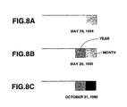
- FIGS. 8A to 8C show an actual example of the document in which other color tag is printed out.
- the actual example of the color tag which is printed out in the document shown in FIGS. 8A to 8C shows the example printed in "upper-right corner" of the document among the additional areas which are set in the additional area column in the color information table shown in FIGS. 4A to 4C.
- Two color tags are printed out in the examples shown in FIGS. 8A to 8C. Left tag indicates "Year" and right tag indicates "month”. In such a manner, a plurality of color tags are printed out, so that identification information can be indicated in detail.
- FIGS. 9A and 9B other print example of the,color tag is shown in FIGS. 9A and 9B.
- the color tag shown in FIG. 9A is printed out at the peripheral portion of the document.
- a color print is carried out at the peripheral portion of the document.
- FIG. 9B when the documents are filed, a printed color portion can be seen from the portion shown by an arrow in FIG. 9B.
- the issue year, the issue month, etc. can be identified by seeing the colored portion.
- the RAM 4 is provided with the color information memory 4d for storing the color information table in which the definition information for defining the cell information to be detected in the document data, the additional area information showing a color tag print position and the dictionary specification information are set, and the color definition dictionary memory 4e for storing various color definition dictionary tables corresponding to the dictionary specification information which is set in the color information table.
- the color information table the cell information to be detected, the item name, the additional area information and the dictionary specification information can be optionally set.
- the evaluation condition and the color information (the color and a tone number) according to the evaluation condition are previously set for each item name to be detected. Accordingly, it is not necessary to set the color information table and the color definition dictionary table for each document data. It is possible to reduce time and labor for defining the color information.
- the cell in which the item to be detected in the document data to be printed out is set or the additional area in the document in which the color tag is to be printed out is displayed with color, and it is color-printed out.
- the color definition dictionary table can be changed, and the item to be detected in the document data to be printed out, the color and the position of the color tag print area can be changed.
- the sorted result can be easily printed out for each color.
- a document management can be easily carried out.
- the method is applied to the application program provided with a function of making the document data, so that a print function can be improved.
- the document print process of the first embodiment shows such a case that the color of the color tag and the print position are changed according to the evaluation condition corresponding to the cell data to be detected.
- the process may be used in order to printout a background color all over the document data.
- each setting item can be optionally set.
- the evaluation condition of the cell to be detected can be optionally set, and a variation of a print mode of the document data in which the color tag is printed out can be easily carried out.
- the document data can be sorted in detail.
- FIGS. 10 to 16 show an embodiment of a computer system 10 in which a second embodiment according to the present invention is applied.
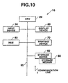
- FIG. 10 is a block diagram showing a main portion of the computer system 10.
- the computer system 10 comprises a CPU 20, an input device 30, a RAM 40, a storage device 50, a storage medium 60, a printing device 70 and a display device 80. Each device is connected to a bus line 90.
- the CPU (Central Processing Unit) 20 stores an application program specified among the Windows system program as a GUI and the various application programs corresponding to the Windows system which are stored in the storage device 50 and various instructions or data inputted from the input device 30 in a work memory 40a in the RAM 40. According to the input instruction and input data, various processing are operated based on the application program stored in the RAM 40. The result of processing is stored in the work memory 40a in the RAM 40, and it is displayed in the display device 80. The result of processing stored in the work memory 40a is saved in a given address of the storage device 50 which is instructed by the input device 30.
- the CPU 20 obtains the document data to be printed out by the document data memory 40b in the RAM 40.
- An arrangement information of the group of cells in which a halftone print is instructed in each cell data is stored in a data-2 memory 40d in the RAM 40.
- the CPU 20 determines a sort direction of numerical value data in an arranged objective cell. A rate of change is calculated from the number of cells to be printed out and the number of halftone levels.
- cells are printed out with colors in a sort order with changing the number of halftone levels of the specified color according to the rate of change, so that a plurality of cells are color printed in a sort order.
- the input device 30 comprises the keyboard provided with the cursor key, the numerical input key, various function keys, etc. and the mouse being the pointing device.
- the press signal indicative of the pressed key on the keyboard is supplied to the CPU 20.
- the operation signal by the mouse is outputted to the CPU 20.
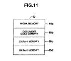
- the RAM (Random Access Memory) 40 comprises the work memory 40a for storing the specified application program, the input instruction, the input data, the result of processing, etc., the document data memory 40b for storing the document data, the data-1 memory 40c which stores the set color information for coloring the cell to be halftone-printed in the document printout process, the changing direction information specified in the document printout process and a start/end cell coordinate information, and the data-2 memory 40d which stores the arrangement information of the cell corresponding to the cell to be halftone-printed in the document printout process.
- the storage device 50 has the storage medium 60 in which the program, the data, etc. are previously stored.
- the storage medium 60 comprises the magnetic recording media, the optical recording media or the semiconductor memory.
- the storage medium 60 is fixedly housed in the storage device 50, or the storage medium 60 is detachably mounted to the storage device 50.
- the storage medium 60 stores the Windows system program as the GUI, various application programs corresponding to the Windows system, the data processed by the document printout processing program and each processing program, etc.
- the program, the data, etc. to be stored in the storage medium 60 may be received from another equipment connected via the communication line, etc..
- the present equipment does not comprise the storage device 50 and another equipment connected via the communication line, etc. are provided with the storage device 50 so that the program and the data stored in the storage medium 60 can be used via the communication line.
- the printing device 70 prints out the printout data (the document data, etc.) inputted from the CPU 20 with the specified color.
- the display device 80 comprises the CRT (Cathode Ray Tube) display, a liquid crystal display device and the like.
- the display data inputted from the CPU 20 is displayed with the specified color.
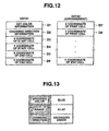
- FIG. 12 shows various information stored in the data-1 memory 40c and the cell arrangement information stored in the data-2 memory 40d.
- a set color information D1 for coloring the cell to be halftone-printed in the document print our process a changing direction information D2 which instructs the changing direction (ascending order, descending order, etc.) of the numerical value data specified in the document print our process
- an X coordinate D3 and a Y coordinate D4 of a start cell in the specified group of cells to be printed out and an X coordinate D5 and a Y coordinate D6 of an end cell in the group of cells to be printed out.
- the data-2 memory 40d stores as many X coordinates D7 and Y coordinates D8 of the arrangement position of each cell in the group of cells to be printed out which is specified in the document printout process as the cell to be printed out for each cell to be printed out.
- FIG. 13 shows the contents the setting items which are set before the document printout process.
- the setting items for printing out the document data shown in FIG. 13 comprises a specified color for setting a printing color of a range for setting the specified group of cells to be printed out when the group of cells to be printed out is halftone-printed, and a changing direction for setting the changing direction of the numerical value data in the group of cells to be printed out.
- FIG. 13 shows such a mode that "blue” is set in the specified color, "A1 : A7” is set in the range and “ascending order” is set in the changing direction.
- “A1 : A7” in the range shows the group of cells to be printed out which ranges from a cell A1 to a cell A7.
- Each setting item which is set in such a manner is stored in the data-1 memory 40c in the RAM 40.
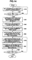
- the document printout process operated by the CPU 20 will be described with reference to a flow chart shown in FIG. 14.
- the program for realizing each function described in the flow chart is stored in the storage medium 60 in the program code which can be read by the CPU 20.
- the document printout process is instructed by the input from the input device 30.
- the CPU 20 starts the document printout process.
- the document form of the document data is read from the document data memory 40c in the RAM 40.
- the form is developed in the work memory 40a, and it is displayed in the display device 80.
- the document data is developed in the developed document form, and it is displayed in the display device 80.
- the cell arrangement information in the group of cells to be halftone-printed is stored in the data-2 memory 40d in the RAM 40 as shown in FIG. 12 (step S10).
- step S20 It is determined whether or not another specified cell to be halftone-printed exists (step S20). When there exists another cell to be halftone-printed, the process is returned to the step S10, so that a store operation of the arrangement information into the data-2 memory 40d is repeated. When there is no cell to be halftone-printed, the sort direction of cell to be printed out is determined according to the changing direction information stored in the data-1 memory 40c in the RAM 40, for example, according to the ascending order, based on the item set as shown in FIG. 13 (step S30).
- the numerical value data of the cells to be printed out according to the arrangement information stored in the data-2 memory 40d is sorted according to the sort direction determined in the step S30 (step S40). That is, the numerical value data of the cells to be printed out is sorted in the ascending order.
- the rate of change of the set color is calculated based on the sorted cells (step S50). That is, according to a relationship between the number of the cells to be printed out and the halftone number which is set in the printing device 70, the rate of change between the sorted cells is calculated as "halftone number/number of cells".
- step S60 an initial value of the set color is obtained. That is, "blue” shown in FIG. 13 is obtained, and it is set on the work memory 40a (step S60).
- step S70 an arrangement of the cells to be printed out which is stored in the data-2 memory 40d
- step S70 the halftone is changed according to the rate of change calculated in the step S50, so that "blue” being the color information in the memory which is set in the step S60 is displayed in the display device 80.
- the displayed contents are printed out with color by the printing device 70 with a predetermined paper (step S80).
- the group of cells to be halftone-printed is specified as the range (Al to A7) as shown in FIG. 13 relative to the document data shown in FIG. 15A
- the number of the cells A1 to A7 to be printed out is "7”
- a halftone number which is set relative to the printing device 70 is "3"
- the rate of change to be calculated in the step S50 is 1 ⁇ (3/7) ⁇ 0.42.
- the halftone number is set to "1”.
- the set color "blue” is displayed in the cell A1 with the halftone number "1".
- the rate of change is calculated and the halftone number is set.
- the rate of change of the cell A2 becomes 2 ⁇ (3/7) ⁇ 0.85.
- the halftone number is set to "1".
- the set color "blue” is displayed in the cell A2 with the halftone number "1".
- the rate of change of the cell A3 becomes 3 ⁇ (3/7) ⁇ 1.1.
- the halftone number is set to "2".
- the set color "blue” is displayed in the cell A3 with the halftone number "2”.
- the rate of change of the cell A4 becomes 4 ⁇ (3/7) ⁇ 1.7.
- the halftone number is set to "2”.
- the set color "blue” is displayed in the cell A4 with the halftone number "2".
- the rate of change of the cell AS becomes 5 ⁇ (3/7) ⁇ 2.1.
- the halftone number is set to "3".
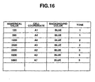
- the specified color "blue” is displayed in each cell which is specified to be halftone-printed with the halftone numbers "1" to “3” according to the rate of change.
- the cells are sorted according to "ascending order” being the sort direction, so that the arrangement is changed.
- the arrangement of the cells to be printed out is changed, and the cell coordinate, a set background color "blue” and the halftone numbers "1 to 3" are set so as to be matched to the arrangement.
- the process is returned to step S90, so that it is determined whether or not there remains any cell to be printed out.
- the process is returned to the step S70, and the process is returned to a halftone number changing process according to the process of setting the color information and the rate of change of the color information in the step S80.
- the process is completed.
- the rate of change is calculated for each cell based on the halftone number which is set relative to the printing device 70 and the number of cells according to the previously specified cell range to be halftone-printed, a basic color and the changing direction (sort direction).
- the cell order is determined according to the specified changing direction. According to the rate of change and the cell order, the basic color and the halftone number are automatically set as the background color of each cell, and the color print is outputted from the printing device 70. Accordingly, it is not necessary to define a color specification for each cell, and it is possible to save time and labor to define the color information in the cell to be printed out.
- the halftone number is automatically set relative to each cell in the group of cells to be printed out which is instructed in the document data to be printed out, according to the rate of change for each cell and the cell order.
- a color display is carried out, and the color print is outputted. Accordingly, according to a change condition in the group of cells to be printed out which is specified when the document data is printed out, a color identification output can be easily carried out.
- the analysis result can be easily outputted by the change of the halftone number of the specified color.
- the application program provided with the function of making the document data is applied, so that the data output function can be improved.
- the halftone number (printing density) of the background color of the cell is changed according to the rate of change for each cell and the sort order is described.
- the pitch of a meshing pattern may be changed.
- a color of the character printed by the numerical value data in the cell may be changed.
- a character size of the numerical value data in the cell may be changed.
- the analysis result can be easily outputted as the change of the meshing pattern, the change of the character color and the change of the character size.
- a document output device in which the user can simply identify a type of the document data and an inherent information of the document data by its appearance at a glance according to a color of an image which is additionally printed at a predetermined position on the document data.
Landscapes
- Engineering & Computer Science (AREA)
- Theoretical Computer Science (AREA)
- Physics & Mathematics (AREA)
- General Physics & Mathematics (AREA)
- General Engineering & Computer Science (AREA)
- Business, Economics & Management (AREA)
- General Health & Medical Sciences (AREA)
- Health & Medical Sciences (AREA)
- Artificial Intelligence (AREA)
- Audiology, Speech & Language Pathology (AREA)
- Computational Linguistics (AREA)
- Tourism & Hospitality (AREA)
- Economics (AREA)
- Human Resources & Organizations (AREA)
- Marketing (AREA)
- Primary Health Care (AREA)
- Strategic Management (AREA)
- General Business, Economics & Management (AREA)
- Document Processing Apparatus (AREA)
- Processing Or Creating Images (AREA)
- Record Information Processing For Printing (AREA)
Claims (8)
- Dokumentausgabevorrichtung zum Ausgeben eines Ausgabebildes mit einem farbigen Abschnitt, der in Abhängigkeit von empfangenen Dokumentdaten eingefärbt ist, gekennzeichnet durch:wobei die Ausgabeeinrichtung (7, 8) das Ausgabebild mit den empfangenen Dokumentdaten und außerdem mit dem eingefärbten Abschnitt ausgibt, der eine Farbe gemäß der bestimmten Farbinformation an einer Position gemäß der Bereichsinformation der zweiten Speichereinrichtung (4d) aufweist.eine erste Speichereinrichtung (4e) zur Speicherung vorbestimmter Daten in Verbindung mit Farbinformation,eine zweite Speichereinrichtung (4d) zur Speicherung von Bereichsinformation, die eine Position zur Ausgabe von Farbinformation angibt,eine Farbbestimmungseinrichtung (2) zur Erfassung der vorbestimmten Daten, die in dem ersten Speicher (4e) gespeichert sind, in den empfangenen Dokumentdaten und zum Bestimmen von Farbinformation entsprechend zu den erfassten Daten der ersten Speichereinrichtung (4e) und
- Dokumentausgabevorrichtung nach Anspruch 1, wobei die vorbestimmten Daten, die in der ersten Speichereinrichtung (4d) gespeichert sind, zumindest entweder ein Datum, ein Kunde oder ein Dokumenttyp sind.
- Dokumentausgabevorrichtung gemäß Anspruch 1 oder 2, wobei die Position, die in der Speichereinrichtung (4d) gespeichert ist, ein Randabschnitt, ein Umfangsabschnitt oder ein Hintergrund eines Ausgabebildes ist.
- Dokumentausgabevorrichtung nach einem der Ansprüche 1 bis 3, wobei das Dokument eine Mehrzahl von Datenelementen umfasst, von denen jedes Dokumentendaten in einer vorbestimmten Form enthält, und die Dokumentausgabevorrichtung außerdem eine Einrichtung zur Bestimmung eines der Mehrzahl der Datenelemente umfasst,
wobei die zweite Speichereinrichtung (4d) eine Mehrzahl von Bereichsinformationen in Verbindung mit der Mehrzahl von Datenelementen speichert,
wobei die Dokumentausgabevorrichtung außerdem eine Bereichsbestimmungseinrichtung zur Bestimmung einer der Mehrzahl der Bereiche basierend auf dem bestimmtem der Mehrzahl der Datenelemente aus der zweiten Speichereinrichtung (4d) umfasst,
wobei die Farbbestimmungseinrichtung (2) die vorbestimmten Daten für das bestimmte Datenelement erfasst und
wobei die Ausgabeeinrichtung (7, 8) das Ausgabebild mit dem Farbabschnitt an einer Position ausgibt, die von der Bereichsbestimmungseinrichtung bestimmt ist. - Dokumentausgabevorrichtung nach Anspruch 4, wobei
die Bestimmungseinrichtung eine Mehrzahl vorbestimmter Datenelemente bestimmt,
die Bereichsbestimmungseinrichtung entsprechende Positionen für die bestimmte Mehrzahl der Datenelemente bestimmt,
die Farbbestimmungseinrichtung entsprechende Farben für die bestimmte Mehrzahl der Datenelemente bestimmt und
die Ausgabeeinrichtung das Dokument mit einer Mehrzahl von eingefärbten Abschnitten ausgibt, die an Positionen ausgegeben werden, die von der Bereichsbestimmungseinrichtung bestimmt ist, und mit einer Farbe, die von der Farbbestimmungseinrichtung bestimmt ist. - Dokumentausgabevorrichtung nach Anspruch 4 oder 5, wobei die Farbbestimmungseinrichtung eine Farbtabelle zur Speicherung von Beurteilungsbedingungen, die sich auf die Dokumentendaten der bestimmten Datenelemente beziehen, und von Farben, die den Beurteilungsbedingungen entsprechen, umfasst und bestimmt, welche der Beurteilungsbedingungen basierend auf den Dokumentendaten des bestimmten Datenelementes erfüllt ist, und die Farbe des eingefärbten, an der von der Bereichsbestimmungseinrichtung bestimmten zu druckenden Position basierend auf der Beurteilungsbedingung bestimmt, die von den Dokumentendaten des bestimmten Datenelementes erfüllt ist.
- Verfahren zum Ausgeben eines Ausgabebildes basierend auf empfangenen Dokumentendaten unter Verwendung einer Tabelle (4e) vorbestimmter Daten, die in Verbindung mit Farbinformation gespeichert sind, und unter Verwendung vorbestimmter Bereichsinformation (4d), die eine Position zum Ausgeben von Farbinformation angibt, wobei das Verfahren die Schritte umfasst:Erfassen der vorbestimmten Daten, die in der Tabelle (4e) gespeichert sind, innerhalb der empfangenen Dokumentendaten,Bestimmen von Farbinformation für alle erfassten, vorbestimmten Daten aus der Tabelle (4e) undAusgeben eines Ausgabebildes mit den erfassten empfangenen Dokumentendaten und außerdem mit einem eingefärbten Abschnitt, der eine Farbe gemäß der bestimmten Farbinformation an einer Position gemäß der Bereichsinformation (4d) aufweist.
- Computerprogrammprodukt mit einem computerlesbaren Medium, auf dem ein computerlesbarer Programmcode enthalten ist, wobei der Programmcode zur Ausführung aller Schritte des Anspruchs 7 eingerichtet ist.
Applications Claiming Priority (7)
| Application Number | Priority Date | Filing Date | Title |
|---|---|---|---|
| JP11090496 | 1996-05-01 | ||
| JP110904/96 | 1996-05-01 | ||
| JP11090496A JP3986102B2 (ja) | 1996-05-01 | 1996-05-01 | 帳票印刷装置 |
| JP11651496 | 1996-05-10 | ||
| JP116514/96 | 1996-05-10 | ||
| JP11651496A JP3407537B2 (ja) | 1996-05-10 | 1996-05-10 | 帳票出力方法 |
| PCT/JP1997/001485 WO1997041522A1 (en) | 1996-05-01 | 1997-04-30 | Document output device |
Publications (2)
| Publication Number | Publication Date |
|---|---|
| EP0836728A1 EP0836728A1 (de) | 1998-04-22 |
| EP0836728B1 true EP0836728B1 (de) | 2003-07-16 |
Family
ID=26450421
Family Applications (1)
| Application Number | Title | Priority Date | Filing Date |
|---|---|---|---|
| EP97918339A Expired - Lifetime EP0836728B1 (de) | 1996-05-01 | 1997-04-30 | Dokumentausgabegerät |
Country Status (8)
| Country | Link |
|---|---|
| US (1) | US6298359B1 (de) |
| EP (1) | EP0836728B1 (de) |
| KR (1) | KR100321811B1 (de) |
| CN (1) | CN1146823C (de) |
| DE (1) | DE69723524T2 (de) |
| MY (1) | MY120211A (de) |
| TW (1) | TW343316B (de) |
| WO (1) | WO1997041522A1 (de) |
Families Citing this family (7)
| Publication number | Priority date | Publication date | Assignee | Title |
|---|---|---|---|---|
| JP3399211B2 (ja) * | 1996-02-14 | 2003-04-21 | カシオ電子工業株式会社 | 記録装置 |
| JP3946043B2 (ja) * | 1999-09-30 | 2007-07-18 | 富士通株式会社 | 帳票識別装置及び識別方法 |
| US20040139113A1 (en) * | 2002-10-29 | 2004-07-15 | Listou Robert Eugene | Computer program for rapidly editing and visually distinguishing elements of presentation of parametric text data objects and associated files |
| KR100680267B1 (ko) * | 2005-09-16 | 2007-02-08 | 주식회사 인포피아 | 식별정보를 포함하는 바이오 센서 및 바이오 센서의식별정보 판독장치 |
| JP2007141159A (ja) * | 2005-11-22 | 2007-06-07 | Fuji Xerox Co Ltd | 画像処理装置、画像処理方法、及び画像処理プログラム |
| JP4952810B2 (ja) * | 2010-03-03 | 2012-06-13 | コニカミノルタビジネステクノロジーズ株式会社 | 画像形成装置および印刷物の作成方法 |
| KR20180000500U (ko) | 2016-08-12 | 2018-02-21 | 박기두 | 소방용 급수펌프의 호스 연결구 |
Citations (1)
| Publication number | Priority date | Publication date | Assignee | Title |
|---|---|---|---|---|
| US5463724A (en) * | 1992-04-08 | 1995-10-31 | Borland International, Inc. | System and methods for improved spreadsheet interface with user-familiar objects |
Family Cites Families (12)
| Publication number | Priority date | Publication date | Assignee | Title |
|---|---|---|---|---|
| JPH0688427B2 (ja) * | 1987-04-15 | 1994-11-09 | キヤノン株式会社 | 出力装置 |
| US5123088A (en) * | 1988-06-27 | 1992-06-16 | Nippon Telegraph And Telephone Corp. | Method and apparatus for creating and displaying navigators for guiding to related image information |
| JP2523898B2 (ja) * | 1988-10-24 | 1996-08-14 | ゼロックス コーポレーション | 原稿印刷ジョブ処理方法 |
| EP0416818B1 (de) * | 1989-08-31 | 1995-02-15 | Canon Kabushiki Kaisha | Verfahren und Apparat für Dokument-Bearbeitung |
| JP2895129B2 (ja) * | 1990-01-22 | 1999-05-24 | 株式会社東芝 | 論理セルの配置処理方法及び論理セルの配置処理装置 |
| US5231577A (en) * | 1990-04-06 | 1993-07-27 | Microsoft Corporation | Method and system for processing formatting information in a spreadsheet |
| JP3092711B2 (ja) * | 1990-09-11 | 2000-09-25 | キヤノン株式会社 | 出力制御装置及び方法 |
| US5644692A (en) * | 1991-12-06 | 1997-07-01 | Lucent Technologies Inc. | Information display apparatus and methods |
| CA2082848C (en) * | 1991-12-06 | 2000-12-19 | Stephen G. Eick | Apparatus for selective simultaneous display of information about a plurality of events |
| US5615320A (en) * | 1994-04-25 | 1997-03-25 | Canon Information Systems, Inc. | Computer-aided color selection and colorizing system using objective-based coloring criteria |
| US5909539A (en) * | 1995-09-20 | 1999-06-01 | Casio Computer Co., Ltd. | Image generating system and method |
| US5960448A (en) * | 1995-12-15 | 1999-09-28 | Legal Video Services Inc. | System and method for displaying a graphically enhanced view of a region of a document image in which the enhanced view is correlated with text derived from the document image |
-
1997
- 1997-04-30 KR KR1019970709991A patent/KR100321811B1/ko not_active Expired - Fee Related
- 1997-04-30 TW TW086105737A patent/TW343316B/zh not_active IP Right Cessation
- 1997-04-30 CN CNB971904332A patent/CN1146823C/zh not_active Expired - Fee Related
- 1997-04-30 US US08/981,784 patent/US6298359B1/en not_active Expired - Lifetime
- 1997-04-30 WO PCT/JP1997/001485 patent/WO1997041522A1/en not_active Ceased
- 1997-04-30 MY MYPI97001889A patent/MY120211A/en unknown
- 1997-04-30 EP EP97918339A patent/EP0836728B1/de not_active Expired - Lifetime
- 1997-04-30 DE DE69723524T patent/DE69723524T2/de not_active Expired - Lifetime
Patent Citations (1)
| Publication number | Priority date | Publication date | Assignee | Title |
|---|---|---|---|---|
| US5463724A (en) * | 1992-04-08 | 1995-10-31 | Borland International, Inc. | System and methods for improved spreadsheet interface with user-familiar objects |
Non-Patent Citations (5)
| Title |
|---|
| B. Corrie, P. Mackerras: Data Shaders, Proceedings Visualisation 93, pp. 275-282, IEEE Computer Society Press, October 1993. * |
| C. Plaisant, B. Milash, A. Rose, S. Widoff. B. Shneidermann: Lifelines: Visualizing Personal Histories, Conference Proceedings on Human factors in Computing Science, Vancouver, Canada, April 13-16, 1996. * |
| D. Keim, H.-P. Kriegel: VisDB: Database Exploration Using Multidimensional Visualisation, IEEE Computer Graphics and Applications, September 1994, pp. 40-49. * |
| P. Lucas, S. Roth, C. Gomberg: Visage: Dynamic Information Exploration, Procedings CHI 96, April 13-18, 1996. * |
| W.-A. Jungmeister, D. Turo: Adapting Treemaps to Stock Portfolio Visualization, University of Maryland, Center for Automation Research, Technical Report CAR-TR-648, CS-TR-2996, November 1992. * |
Also Published As
| Publication number | Publication date |
|---|---|
| HK1015483A1 (en) | 1999-10-15 |
| KR100321811B1 (ko) | 2002-06-22 |
| KR19990028668A (ko) | 1999-04-15 |
| DE69723524D1 (de) | 2003-08-21 |
| CN1146823C (zh) | 2004-04-21 |
| DE69723524T2 (de) | 2004-01-29 |
| EP0836728A1 (de) | 1998-04-22 |
| TW343316B (en) | 1998-10-21 |
| WO1997041522A1 (en) | 1997-11-06 |
| CN1189905A (zh) | 1998-08-05 |
| MY120211A (en) | 2005-09-30 |
| US6298359B1 (en) | 2001-10-02 |
Similar Documents
| Publication | Publication Date | Title |
|---|---|---|
| EP0838064B1 (de) | Dokumentausgabegerät | |
| US5555101A (en) | Forms creation and interpretation system | |
| US5302969A (en) | Document format setting method and apparatus | |
| US5966127A (en) | Graph processing method and apparatus | |
| EP0536894B1 (de) | Bildverarbeitungssystem und Verfahren zur automatischen Objektauswahl | |
| US6959414B1 (en) | Form editing method and apparatus, and storage medium storing computer-readable program | |
| CN113997696B (zh) | 一种产品包装箱用标签打印系统、方法、终端及存储介质 | |
| US6298359B1 (en) | Document output device | |
| US5719960A (en) | System for dispatching task orders into a user network and method | |
| JP3986102B2 (ja) | 帳票印刷装置 | |
| JPH1049324A (ja) | 帳票処理装置 | |
| JP4075999B2 (ja) | 帳票出力装置 | |
| US5539904A (en) | Method for designation of data in a data bank and extraction | |
| Milne | Presentation graphics for engineering, science and business | |
| EP0637811B1 (de) | Verfahren zum Definieren mehrerer Formulardefinitionsdatensätze | |
| JPH09305352A (ja) | 帳票出力方法 | |
| JPH09305371A (ja) | 数値出力方法 | |
| JPH0764981A (ja) | 文書処理装置 | |
| JPH08339371A (ja) | 文書出力装置及び文字修飾方法 | |
| JPH04168073A (ja) | ラベル印字装置 | |
| GB2106676A (en) | Printing position setting apparatus with printer | |
| HK1006363A (en) | System for dispatching task orders into a user network and method | |
| HK1015483B (en) | Document printing device | |
| JPH10143579A (ja) | 表処理装置 | |
| JPH03198150A (ja) | 文書作成装置 |
Legal Events
| Date | Code | Title | Description |
|---|---|---|---|
| PUAI | Public reference made under article 153(3) epc to a published international application that has entered the european phase |
Free format text: ORIGINAL CODE: 0009012 |
|
| 17P | Request for examination filed |
Effective date: 19980119 |
|
| AK | Designated contracting states |
Kind code of ref document: A1 Designated state(s): DE GB |
|
| RAP1 | Party data changed (applicant data changed or rights of an application transferred) |
Owner name: CASIO COMPUTER CO., LTD. |
|
| 17Q | First examination report despatched |
Effective date: 20010711 |
|
| GRAH | Despatch of communication of intention to grant a patent |
Free format text: ORIGINAL CODE: EPIDOS IGRA |
|
| GRAH | Despatch of communication of intention to grant a patent |
Free format text: ORIGINAL CODE: EPIDOS IGRA |
|
| GRAA | (expected) grant |
Free format text: ORIGINAL CODE: 0009210 |
|
| AK | Designated contracting states |
Designated state(s): DE GB |
|
| REG | Reference to a national code |
Ref country code: GB Ref legal event code: FG4D |
|
| REF | Corresponds to: |
Ref document number: 69723524 Country of ref document: DE Date of ref document: 20030821 Kind code of ref document: P |
|
| PLBE | No opposition filed within time limit |
Free format text: ORIGINAL CODE: 0009261 |
|
| STAA | Information on the status of an ep patent application or granted ep patent |
Free format text: STATUS: NO OPPOSITION FILED WITHIN TIME LIMIT |
|
| 26N | No opposition filed |
Effective date: 20040419 |
|
| PGFP | Annual fee paid to national office [announced via postgrant information from national office to epo] |
Ref country code: GB Payment date: 20150420 Year of fee payment: 19 Ref country code: DE Payment date: 20150421 Year of fee payment: 19 |
|
| REG | Reference to a national code |
Ref country code: DE Ref legal event code: R119 Ref document number: 69723524 Country of ref document: DE |
|
| GBPC | Gb: european patent ceased through non-payment of renewal fee |
Effective date: 20160430 |
|
| PG25 | Lapsed in a contracting state [announced via postgrant information from national office to epo] |
Ref country code: DE Free format text: LAPSE BECAUSE OF NON-PAYMENT OF DUE FEES Effective date: 20161101 Ref country code: GB Free format text: LAPSE BECAUSE OF NON-PAYMENT OF DUE FEES Effective date: 20160430 |