EP0835833A2 - Method and device for separating stacked flat products and use of the device in the packaging of cigarettes - Google Patents
Method and device for separating stacked flat products and use of the device in the packaging of cigarettes Download PDFInfo
- Publication number
- EP0835833A2 EP0835833A2 EP97117459A EP97117459A EP0835833A2 EP 0835833 A2 EP0835833 A2 EP 0835833A2 EP 97117459 A EP97117459 A EP 97117459A EP 97117459 A EP97117459 A EP 97117459A EP 0835833 A2 EP0835833 A2 EP 0835833A2
- Authority
- EP
- European Patent Office
- Prior art keywords
- transport device
- fabric
- transport
- lowest
- edge
- Prior art date
- Legal status (The legal status is an assumption and is not a legal conclusion. Google has not performed a legal analysis and makes no representation as to the accuracy of the status listed.)
- Granted
Links
Images

Classifications
-
- B—PERFORMING OPERATIONS; TRANSPORTING
- B65—CONVEYING; PACKING; STORING; HANDLING THIN OR FILAMENTARY MATERIAL
- B65H—HANDLING THIN OR FILAMENTARY MATERIAL, e.g. SHEETS, WEBS, CABLES
- B65H3/00—Separating articles from piles
- B65H3/08—Separating articles from piles using pneumatic force
- B65H3/12—Suction bands, belts, or tables moving relatively to the pile
- B65H3/122—Suction tables
-
- B—PERFORMING OPERATIONS; TRANSPORTING
- B65—CONVEYING; PACKING; STORING; HANDLING THIN OR FILAMENTARY MATERIAL
- B65H—HANDLING THIN OR FILAMENTARY MATERIAL, e.g. SHEETS, WEBS, CABLES
- B65H3/00—Separating articles from piles
- B65H3/46—Supplementary devices or measures to assist separation or prevent double feed
- B65H3/56—Elements, e.g. scrapers, fingers, needles, brushes, acting on separated article or on edge of the pile
-
- B—PERFORMING OPERATIONS; TRANSPORTING
- B65—CONVEYING; PACKING; STORING; HANDLING THIN OR FILAMENTARY MATERIAL
- B65H—HANDLING THIN OR FILAMENTARY MATERIAL, e.g. SHEETS, WEBS, CABLES
- B65H2406/00—Means using fluid
- B65H2406/30—Suction means
- B65H2406/34—Suction grippers
- B65H2406/342—Suction grippers being reciprocated in a rectilinear path
-
- B—PERFORMING OPERATIONS; TRANSPORTING
- B65—CONVEYING; PACKING; STORING; HANDLING THIN OR FILAMENTARY MATERIAL
- B65H—HANDLING THIN OR FILAMENTARY MATERIAL, e.g. SHEETS, WEBS, CABLES
- B65H2406/00—Means using fluid
- B65H2406/30—Suction means
- B65H2406/35—Other elements with suction surface, e.g. plate or wall
- B65H2406/351—Other elements with suction surface, e.g. plate or wall facing the surface of the handled material
-
- B—PERFORMING OPERATIONS; TRANSPORTING
- B65—CONVEYING; PACKING; STORING; HANDLING THIN OR FILAMENTARY MATERIAL
- B65H—HANDLING THIN OR FILAMENTARY MATERIAL, e.g. SHEETS, WEBS, CABLES
- B65H2406/00—Means using fluid
- B65H2406/30—Suction means
- B65H2406/36—Means for producing, distributing or controlling suction
Definitions
- the invention relates to a method and an apparatus for Separation of stacked fabrics from a fabric stack, the bottom sheet of the sheet stack by negative pressure from a transport device is held and deducted.
- Such a device is known from US-A-3 782 716.
- the separation device described there has one Transport carriage on, its two side areas after fall down. There are several in each side area Openings are provided that are even along the entire length the side areas are distributed.
- To separate one The fabric is over the in the sloping side areas openings made on the lowest fabric a vacuum is created, causing the edge areas of the lowest fabric bent and on the side areas of the transport carriage are fixed. Thereupon will the transport carriage is set to the side and that lowest, fixed structure on the slide below isolated through a scraper. Behind the scraper the lowermost fabric that is pushed forward onto a roll hand over what the vacuum must be switched off. Of the The carriage then returns to its starting position, the vacuum is switched on again and the separation process is repeated.
- a disadvantage of the device of US Pat. No. 3,782,716 is that that by controlling the vacuum only relatively small Separation speeds (approx. 250 pieces per minute) can be achieved.
- the object of the present invention is therefore a method and to provide a device that is higher Enable separation speed.
- the lowest flat structure acts due to matching the length of the rear, from suction openings free area of the transport device, the time and the speed of the forward and backward movement of the transport device and the timing and speed of the Further transport of the lowest flat structure as a kind of vacuum slide between the openings over which Vacuum is applied, and the second lowest fabric. Only when the transport device is already back is in the forward movement or preferably its backward Has reached position again, the lowest flat structure completely subtracted so that only at this time the vacuum then acts on the next lowest fabric can. It is also possible that the transport device itself at the time the suction openings are released by the respective lowest sheet is still in its backward movement.
- the lowermost sheet is preferably detached by applying the vacuum and fixing it partially detached fabric on the transport device through the same suction area or the same openings in the top of the transport device, via the negative pressure is applied to the lowest surface structure, because on this The easiest way to perform the procedure.
- the lowermost sheet be through Negative pressure kinked around a line running in the pulling direction or bent, creating a good partial detachment from the overlying fabrics.
- the fabrics used can be any Act fabrics, but at least one of the Edge areas must be bendable.
- Examples of usable Flat structures are paper cuts (e.g. coupons, inserts, Banderoles, brands), cardboard blanks and plastic blanks (e.g. from polyvinyl chloride or a plasticizer-free one Vinyl chloride-vinyl acetate copolymer).
- a sheet of plastic a flexible card (white or colored and, if necessary, with the usual characteristics a check card such as a magnetic stripe or labeling field) be in the form of a standard check card of one size, which are the same or smaller or larger than the size of one usual check card.
- Coupons for example made of paper, are particularly preferred. with a size of approximately 7.5 cm x 4.5 cm, which can be used as side dishes suitable for cigarette boxes. These coupons can be single layer, be two or more layers. For example, a coupon with a length of approx. 22.5 cm x 4.5 cm to a three-layer Coupons of size 7.5 cm x 4.5 cm can be folded. A another alternative is a coupon with a length of 15 cm and a width of 9 cm, once in the longitudinal direction and once in the transverse direction to a (four-layer) coupon with again folded a length of 7.5 cm and a width of 4.5 cm becomes. These coupons can then with the inventive Method and the device according to the invention Cigarette packets are added.
- the device according to the invention contains a receiving device for the fabric stack, a scraper, at least one suction device for detaching downwards at least one that runs parallel to the pulling direction Edge area of the lowest flat structure, one under the receiving device slidably mounted transport device for the isolated fabrics, so that an in the receiving device of inserted fabric stack the transport device rests, and a puller for recording and conveying the respectively advanced, lowest fabric.
- the receiving device can be, for example, a magazine slot with continuous walls or preferably individual narrow, fingers up, one in the direction of transport On the front and on the opposite side, one vertically and longitudinally Transport direction adjustable counterholder.
- a magazine slot with continuous walls or preferably individual narrow, fingers up, one in the direction of transport
- one vertically and longitudinally Transport direction adjustable counterholder On the front and on the opposite side, one vertically and longitudinally Transport direction adjustable counterholder.
- Of the Bracket should go under the bottom edge of the fabric stack suffice to extend a fabric at the rear during the backward movement of the transport device avoid.
- the scraper facilitates the final separation of the bottom, partially detached fabric from the rest of the Fabric stacks.
- This scraper can either be a independent element of the device or part of the receiving device be.
- the scraper Represent the front of the recording device.
- the scraper should be at least to the bottom of the second bottom The fabric is sufficient so that after fixing the lowest fabric the simultaneous extension of a other fabric due to the adhesion between the the two lowest levels despite the separation that has already taken place the or the edge areas is avoided.
- the scraper preferably extends in the region of the or the sloping side areas of the transport device to under the bottom edge of the fabric stack. Is optimal a distance between the surface of the side area or areas the transport device and the lower edge of the scraper, which is slightly larger than the thickness of the one to be separated Fabric. An exact setting of the scraper is not necessary as it is already due to the vacuum fixation a separation has occurred and also the distance between the Top edge of the lowest fixed fabric and the Lower edge of the next fabric in the area of the or the sloping side areas is relatively large. It also hangs the setting range of the one selected in each individual case Degree of lowering of the side area (s).
- the scraper can be in one piece, for example U-shaped, where appropriate, the lower ends of the U-shaped scraper are chamfered.
- the scraper can also consist of two separate parts, again the lower ones Ends corresponding to the sloping side areas of the transport device can be beveled.
- the suction device serves to detach one or both edge areas of the lowest fabric.
- This suction device can be a device connected to a conventional vacuum source be. However, the suction device is preferred Part of the transport device described in more detail below.
- the transport device that can be moved back and forth, preferably one in the usual way (for example using a crank drive) driven transport carriage is used for Advance the lowest fabric.
- the Top of the transport device at least one opening on that with a device for generating negative pressure is connectable so that the lowest fabric on the Transport device held during the forward movement becomes.
- the opening, or openings, over the negative pressure the lowest surface structure is created in the front area of the transport device (preferably in the front half, especially in the front third, especially preferably in the front tenth), while the rear Area has no openings.
- the one in the transport facility The intended opening or openings are marked with connected to a vacuum or suction device and in the Usually circular with a diameter of 1 for example mm to 1 cm. Any vacuum generator system can be used for this are used, for example a water jet pump.
- the opening or openings serve at the same time also for detaching the at least one edge region of the lowest flat structure in each case.
- they are Opening or the openings then in one or both side areas attached to the transport device, again the rear areas of these side areas free of Openings are.
- the number and size of the suction openings depends of course the inherent stability and size of each separating fabric. The higher the inherent rigidity and the larger the size of the fabric, the more more and larger openings are necessary.
- 1 to 4 openings in the front quarter are sufficient, preferably an opening in the front tenth of the or Side areas of the transport device to a detachment and to effect secure fixation.
- the transport device therefore preferably has a or two downwards, parallel to the direction of transport running side areas, in the front areas there are one or more openings to which vacuum is created so that the lowest flat structure first detached and then on the transport device is held.
- a transport device with a one-sided or double-sided lowering of the side areas is selected depends on the fabric to be separated from. For example, if a coupon is to be separated, along its long edge, i.e. along the direction of transport, is folded, there is a one-sided lowering of the Transport device on the side of the folding prefers.
- a one-sided lowering of the transport device points this on a flat side area that is about 30 to 80, preferably 40-70 percent of the total width of the sled and a second side area sloping downwards.
- the top side the transport device has a flat central area, which in typically 30 to 70 percent of the total width of the sled makes up, as well as two usually equally down sloping and equally wide side areas.
- the middle section can be continuous or two or more Areas exist.
- the angle of the side area or slopes downwards is five to twenty, preferably about 10 ° (depending on Material stiffness of the sheet to be separated) opposite the level of the flat side area or the level Middle range.
- the falling side area or areas can also be rounded, which is a good fixation of the fabric allowed on the transport device.
- the width of the transport device corresponds approximately to that Width of the respective fabric.
- the length of the conveyor is approximately equal to the length of the fabric plus the distance covered during the extension or longer. In this way, it will fall out when extended or a decrease in those remaining in the receiving device Avoid fabrics.
- the length of the conveyor can also be a little shorter.
- it is preferred that the leading edge of the transport device when this is for example in the retracted position and before the Fixation and the extension of the lowest fabric is not quite to the rear edge of the front wall of the Receiving device is sufficient so that the fixed fabric something over the front edge of the transport device, for example 0.5 to 3.0 mm, protrudes. This will make the handover of the fixed fabric after it has been pushed out to the puller facilitated.
- the fabric is a bevel on the underside of the leading edge the transport device and its inclination front, for example at an angle of 20 to 50 ° opposite the horizontal.
- the transport device can of course also horizontally or inclined backwards
- the handover can also be done by adjusting the front the transport device to the puller, the forwards the scattered fabrics to be effected.
- This puller is usually located just before the scraper and usually consists of two on usual Wise powered transfer rollers.
- the sheet to be separated is used for the feed through the transport device between the two transfer rollers brought, which then take over the fabric and forward. This is the way traveled of the fabric significantly less than the length of this Fabric.
- Paper coupons have a stroke of approx. 40 mm, for slightly smaller ones Tax stamps of cigarette packs, for example, only 25 mm.
- the time and speed the back and forth movement, the time and the Puller speed (both preferred are continuous, but also be discontinuous can) and the length of the rear free of suction openings Areas of the transport device are coordinated so that the transport device is preferably at least is in its rearward position when the lowest fabric begins to open the suction openings.
- the transport device can also change the opening of the suction openings is still in the backward motion. Then it gets aground the lowest of the permanently switched on vacuum Sheets still during the backward movement of the transport device sucked in, and it can cause a wave formation come to the counterhold.
- the release of the Suction openings either shortly before the end of the backward movement or exactly in the rear end position of the transport device or while they are moving forward, preferably when the transport device is its rear Has reached the end position.
- the suction openings only in the front half, especially that front third or front tenth of the transport device are located.
- the isolated fabric is then removed by the puller promoted further.
- coupons already manufacture cigarette packs, but not yet are surrounded with a transparent film.
- coupons become only with an inner liner wrapped cigarettes fed.
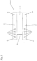
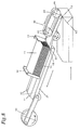
- FIG. 1 shows a transport device 20 in the form of a transport carriage 21 from above.
- the transport carriage 21 has over a flat central area 31 and over the two Side areas 30, which in turn are each in two areas split up.
- the two side areas 30 have each over a front area 29 with four each Openings 26 through which negative pressure can be applied, and a rear region 28 that is free of openings 26.
- the transport carriage 21 has on its front a recess 32 to facilitate the transfer of a advanced, but not shown flat structure.
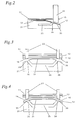
- Fig. 2 shows a separating device with only one three fabrics existing fabric stack 11. At the fabrics are thin two-layer coupons which are folded along their longitudinal edge 15.
- the fabric stack 11 (in a receiving device, not shown) lies on a transport carriage 21, which over a flat area 33 and a laterally sloping side area 30 has.
- the transport carriage 21 is in a known manner linear on rails or other guide devices slidably mounted and is shown by a not shown Drive device driven.
- the movement path of the transport carriage 21 is at an angle of about 30 ° down inclined.
- the recording device (not shown) is in in the same way as the path of the transport carriage 21 inclined at the front so that the fabric stack 11 is through Dead weight bears against a scraper 22, which by a rod, the lower end of which is chamfered becomes.
- This stripper 22 is perpendicular to the direction of movement of the transport carriage 21 arranged.
- the top of the transport carriage 21 faces in the sloping Side area 30 a vacuum or suction opening 26 on by a channel system 25 with a not shown Vacuum source is connected.
- a vacuum or suction opening 26 on by a channel system 25 with a not shown Vacuum source is connected.
- Fig. 2 is a negative pressure to the suction opening 26 via the channel system 25 created so that the lowest sheet 12 is sucked in and is fixed on the sloping side area 30.
- FIG. 3 again shows a transport carriage 21 from the front, that now over a flat central region 31 with two falling Has side areas 30, with a fabric stack 11 from three slightly thicker single-layer fabrics.
- the sloping side areas 30 have suction openings 26, to which vacuum can be applied by means of a vacuum system 25.
- Fig. 3 shows the device before vacuum is applied, so that the edge regions 16 of the lowermost sheet 12 still not from the edge areas of the second lowest fabric 13 are detached.
- FIG. 4 again shows the transport carriage 21 of FIG. 3 the flat central area 31 and the slopes on both sides Side areas 30, the suction openings 26 and the channel 25.
- Das Vacuum is now switched on, so that the lowest fabric 12 sucked onto the surface of the transport slide 21 is.
- the vacuum creates both edge areas 16 of the bottom sheet 12 um in the pulling direction running lines kinked, and the lowest fabric 12 is forced to be its originally rigid and straight form the kinked cross section of the transport carriage 21 adapt. This takes place at the edge regions 16 a separation from the next fabric 13.
- At Feeding the transport carriage 21 becomes the lowest flat structure 12 taken with it because of the vacuum system generated negative pressure held by the carriage 21 and is pulled along.
- the overlying fabric 13 lies with its front edge on the wipers 22, the Lower edge again parallel to the sloping side areas 30 runs on and can thereby the movement of the Transport carriage 12 do not participate, so that by the Feed of the transport carriage 21 and the generated thereby Extending the bottom sheet 12 under the wipers 22 reliable and problem-free separation of the lowermost fabric 12 takes place.
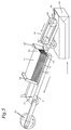
- FIG. 5 is the first one To see step of the separation process.
- A is shown Transport carriage 21 with the two sloping side areas 30 and the flat central area 31.
- the second side area 30 also has one Suction air opening 26, but not in Fig. 5 is recognizable.
- the transport carriage 21 still has a recess 32. Is on the transport carriage a fabric stack 11 made of paper coupons, the front against a scraper 22, which is only partially shown, is present.
- a counterholder 34 At the back of the fabric stack 11 is a counterholder 34. As can be seen from Fig. 5, this is the lowest Sheet 12 by the applied vacuum on the surface of the transport carriage 21 fixed, and the edge areas of the bottom sheet 12 are from the edge areas detached from the next fabric 13.
- a puller in front of the transport carriage 40 which consists of two opposing transfer rollers 42, the Conveyor belt 44 and another roller 46 is made.
- Fig. 5 is just a single sheet 10 on one unfinished pack of 60 cigarettes with an inner liner on it a conveyor belt, not shown, is stored.
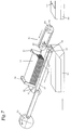
- FIGS. 6 and 8 show all directions of movement (for example the transfer rollers 42, the Conveyor belt 44 or the crank drive 50) by arrows shown (see also above).
- the carriage finally has its maximum front position achieves what is indicated by the movement direction arrow of the Transport carriage 21 and the line perpendicular to it is indicated. It can be clearly seen that the suction air through the suction opening 26 and only on the lowest fabric 12 acts. This lowest fabric 12 is now between the transfer rollers 42, the lower of the transfer rollers 42 in turn in the recess 32 of the transport carriage 21 is located. On this is a good takeover of the isolated fabric 12 possible. The filing of the already isolated The fabric 10 on the cigarette pack 60 is (on right edge of Fig. 7) completed while a second Cigarette pack 62 for the just-separated fabric 12 is transported for handover.
- Fig. 8 shows the next step of the separation, the Slide 21 is already moving backwards and is just before the rear starting position. How 8 shows the lowest flat structure 12 now mostly in the puller 40 and shortly before the shelf on the cigarette pack 62. The rear end of the The fabric 12, however, still covers the suction opening 26, i.e. the rear edge 18 of the fabric 12 has the Suction port 26 not yet released, so that no vacuum on the next lowest fabric 13 acts. In this condition, So right before the transport sled in its rear When the starting position arrives, the lowest fabric appears 12 still as a vacuum slide.
- next step corresponds to that in FIG. 5 shown situation, whereby instead of the isolated there Fabric 10 now the fabric 12 is isolated and the next sheet 13 from the rest of the sheet stack 11 is separated.
Abstract
Description
Die Erfindung betrifft ein Verfahren und eine Vorrichtung zur Vereinzelung gestapelter Flächengebilde aus einem Flächengebildestapel, wobei das unterste Flächengebilde des Flächengebildestapels durch Unterdruck von einer Transporteinrichtung festgehalten und abgezogen wird.The invention relates to a method and an apparatus for Separation of stacked fabrics from a fabric stack, the bottom sheet of the sheet stack by negative pressure from a transport device is held and deducted.
Eine derartige Vorrichtung ist aus der US-A-3 782 716 bekannt. Die dort beschriebene Vereinzelungsvorrichtung weist einen Transportschlitten auf, dessen beiden Seitenbereiche nach unten abfallen. In beiden Seitenbereichen sind jeweils mehrere Öffnungen vorgesehen, die gleichmäßig über die gesamte Länge der Seitenbereiche verteilt sind. Zur Vereinzelung eines Flächengebildes wird über die in den abfallenden Seitenbereichen angebrachten Öffnungen an das unterste Flächengebilde ein Vakuum angelegt, wodurch die Randbereiche des untersten Flächengebildes abgebogen und auf den Seitenbereichen des Transportschlittens fixiert werden. Daraufhin wird der Transportschlitten seitlich in Bewegung gesetzt und das unterste, auf dem Schlitten fixierte Flächengebilde unter einem Abstreifer hindurch vereinzelt. Hinter dem Abstreifer wird das vorgeschobene, unterste Flächengebilde an eine Rolle übergeben, wozu das Vakuum ausgeschaltet werden muß. Der Schlitten fährt dann in seine Ausgangslage zurück, das Vakuum wird wieder eingeschaltet und der Vereinzelungsvorgang wiederholt. Nachteilig bei der Vorrichtung der US-A-3 782 716 ist, daß durch die Steuerung des Vakuums nur relativ geringe Vereinzelungsgeschwindigkeiten (ca. 250 Stück pro Minute) erreicht werden können.Such a device is known from US-A-3 782 716. The separation device described there has one Transport carriage on, its two side areas after fall down. There are several in each side area Openings are provided that are even along the entire length the side areas are distributed. To separate one The fabric is over the in the sloping side areas openings made on the lowest fabric a vacuum is created, causing the edge areas of the lowest fabric bent and on the side areas of the transport carriage are fixed. Thereupon will the transport carriage is set to the side and that lowest, fixed structure on the slide below isolated through a scraper. Behind the scraper the lowermost fabric that is pushed forward onto a roll hand over what the vacuum must be switched off. Of the The carriage then returns to its starting position, the vacuum is switched on again and the separation process is repeated. A disadvantage of the device of US Pat. No. 3,782,716 is that that by controlling the vacuum only relatively small Separation speeds (approx. 250 pieces per minute) can be achieved.
Aufgabe der vorliegenden Erfindung ist es daher, ein Verfahren und eine Vorrichtung zur Verfügung zu stellen, die eine höhere Vereinzelungsgeschwindigkeit ermöglichen.The object of the present invention is therefore a method and to provide a device that is higher Enable separation speed.
Diese Aufgabe wird durch das erfindungsgemäße Verfahren zur Vereinzelung gestapelter Flächengebilde dadurch gelöst, daß das jeweils unterste Flächengebilde zunächst an mindestens einem seiner parallel zur Abziehrichtung verlaufenden Randbereiche durch Unterdruck nach unten vom Rest des Flächengebildestapels abgelöst wird, durch Unterdruck von einer vor- und zurückbewegbaren Transporteinrichtung an mindestens einem Saugbereich festgehalten wird und unter einem Abstreifer hindurch vorgeschoben und weitertransportiert wird und daß der Unterdruck kontinuierlich während der Vor- und Zurückbewegung der Transporteinrichtung anliegt und der Abstand zwischen dem Saugbereich und der Hinterkante des festgehaltenen, untersten Flächengebildes während der Vorwärtsbewegung, der Zeitpunkt und die Geschwindigkeit der Vor- und Zurückbewegung der Transporteinrichtung und der Zeitpunkt und die Geschwindigkeit der Weiterbeförderung des untersten Flächengebildes so aufeinander abgestimmt sind, daß die Transporteinrichtung ihre rückwärtige Endlage etwa zu dem Zeitpunkt erreicht oder ihre Vorwärtsbewegung begonnen hat, wenn die Hinterkante des vorgeschobenen, untersten Flächengebildes den Saugbereich beginnt freizugeben.This object is achieved by the method according to the invention Separation of stacked fabrics solved in that the lowest surface structure at least at first one of its edge areas running parallel to the pulling direction by vacuum down from the rest of the fabric stack is replaced by negative pressure from a pre and retractable transport device on at least one Suction area is held and under a scraper is advanced and transported and that the Vacuum continuously during the back and forth movement of the transport device and the distance between the Suction area and the trailing edge of the captured, lowest Fabric during the forward movement, the time and the speed of the forward and backward movement of the transport device and the timing and speed of the Further conveyance of the lowest fabric to one another are coordinated that the transport device its rear End position reached at about the time or their forward movement started when the trailing edge of the advanced lowermost fabric starts the suction area to release.
Bei dem erfindungsgemäßen Verfahren (und der erfindungsgemäßen Vorrichtung) wirkt das jeweils unterste Flächengebilde aufgrund der Abstimmung der Länge des hinteren, von Saugöffnungen freien Bereichs der Transporteinrichtung, des Zeitpunkts und der Geschwindigkeit der Vor- und Zurückbewegung der Transporteinrichtung und des Zeitpunkts und der Geschwindigkeit der Weiterbeförderung des jeweils untersten Flächengebildes als eine Art Vakuumschieber zwischen den Öffnungen, über die Unterdruck angelegt wird, und dem zweituntersten Flächengebilde. Erst wenn die Transporteinrichtung sich bereits wieder in der Vorwärtsbewegung befindet oder vorzugsweise ihre rückwärtige Lage wieder erreicht hat, wird das unterste Flächengebilde vollständig abgezogen, so daß erst zu diesem Zeitpunkt das Vakuum dann auf das nächstunterste Flächengebilde wirken kann. Es ist auch möglich, daß die Transporteinrichtung sich zum Zeitpunkt der Freigabe der Saugöffnungen durch das jeweils unterste Flächengebilde noch in ihrer Rückwärtsbewegung befindet. Dies birgt jedoch die Gefahr, daß das nächstunterste Flächengebilde dann bei der Beendigung der Rückwärtsbewegung nach hinten, beispielsweise gegen einen Gegenhalter geschoben wird und es zu einer Wellenbildung kommt. Daher ist es bevorzugt, daß die Transporteinrichtung ihre rückwärtige Lage spätestens erreicht hat, wenn die Hinterkante des vorgeschobenen, untersten Flächengebildes beginnt, den Saugbereich freizugeben. Daher kann das Vakuum permanent aufrechterhalten werden und muß nicht für jeden Vereinzelungsvorgang durch eine Ventilsteuerung aus- und eingeschaltet werden. Dies hat den Vorteil, daß viel höhere Vereinzelungsgeschwindigkeiten mit dem erfindungsgemäßen Verfahren von 700 bis 800 oder mehr Stück pro Minute erreicht werden können.In the inventive method (and the inventive Device), the lowest flat structure acts due to matching the length of the rear, from suction openings free area of the transport device, the time and the speed of the forward and backward movement of the transport device and the timing and speed of the Further transport of the lowest flat structure as a kind of vacuum slide between the openings over which Vacuum is applied, and the second lowest fabric. Only when the transport device is already back is in the forward movement or preferably its backward Has reached position again, the lowest flat structure completely subtracted so that only at this time the vacuum then acts on the next lowest fabric can. It is also possible that the transport device itself at the time the suction openings are released by the respective lowest sheet is still in its backward movement. However, this runs the risk of being the next lowest Sheets then at the end of the backward movement pushed backwards, for example against a counterholder and there is a wave formation. Therefore, it is preferred that the transport device its rearward position has reached at the latest when the rear edge of the advanced lowest fabric starts, the suction area to release. Therefore, the vacuum can be maintained permanently are and do not have to be separated by a Valve control can be switched on and off. This has the Advantage that much higher separation speeds with the inventive method from 700 to 800 or more Pieces per minute can be achieved.
Gleichzeitig erfolgt durch die teilweise Ablösung des jeweils untersten Flächengebildes von den darüberliegenden Flächengebilden und den Ausschub unter dem Abstreifer eine saubere Trennung des untersten Flächengebildes, so daß nicht die Gefahr besteht, daß zusammen mit dem untersten Flächengebilde auch darüberliegende Flächengebilde abgeführt werden.At the same time, the partial replacement of each lowermost fabric from the overlying fabrics and the extension under the scraper is a clean one Separation of the lowest fabric so that not There is a risk that together with the lowest fabric also overlying fabrics are removed.
Vorzugsweise erfolgt die Loslösung des untersten Flächengebildes durch den angelegten Unterdruck und die Fixierung dieses teilweise losgelösten Flächengebildes auf der Transporteinrichtung durch denselben Saugbereich oder dieselben Öffnungen in der Oberseite der Transporteinrichtung, über die Unterdruck an das unterste Flächengebilde angelegt wird, da auf diese Weise das Verfahren am einfachsten durchzuführen ist.The lowermost sheet is preferably detached by applying the vacuum and fixing it partially detached fabric on the transport device through the same suction area or the same openings in the top of the transport device, via the negative pressure is applied to the lowest surface structure, because on this The easiest way to perform the procedure.
Es ist weiter bevorzugt, daß das unterste Flächengebilde durch Unterdruck um eine in Abziehrichtung verlaufende Linie abgeknickt oder gebogen wird, wodurch eine gute teilweise Ablösung von den darüberliegenden Flächengebilden erfolgt.It is further preferred that the lowermost sheet be through Negative pressure kinked around a line running in the pulling direction or bent, creating a good partial detachment from the overlying fabrics.
Durch die Loslösung beider Randbereiche des jeweils untersten Flächengebildes wird eine bessere Stabilisierung und damit Haftsicherheit beim Abziehen des Flächengebildes erreicht.By detaching both edge areas of the bottom one Fabric is a better stabilization and thus Adhesion security achieved when removing the fabric.
Bei den verwendeten Flächengebilden kann es sich um beliebige Flächengebilde handeln, wobei jedoch mindestens einer der Randbereiche biegbar sein muß. Beispiele für einsetzbare Flächengebilde sind Papierzuschnitte (z.B. Kupons, Inserts, Banderolen, Marken), Kartonzuschnitte sowie Kunststoffzuschnitte (z.B. aus Polyvinylchlorid oder einem weichmacherfreien Vinylchlorid-Vinylacetat-Copolymer). Vorzugsweise kann ein Flächengebilde aus Kunststoff eine flexible Karte (weiß oder gefärbt und gegebenenfalls mit den üblichen Merkmalen einer Scheckkarte wie Magnetstreifen oder Beschriftungsfeld) in der Form einer üblichen Scheckkarte mit einer Größe sein, die gleich oder kleiner oder größer als die Größe einer üblichen Scheckkarte ist.The fabrics used can be any Act fabrics, but at least one of the Edge areas must be bendable. Examples of usable Flat structures are paper cuts (e.g. coupons, inserts, Banderoles, brands), cardboard blanks and plastic blanks (e.g. from polyvinyl chloride or a plasticizer-free one Vinyl chloride-vinyl acetate copolymer). Preferably can a sheet of plastic a flexible card (white or colored and, if necessary, with the usual characteristics a check card such as a magnetic stripe or labeling field) be in the form of a standard check card of one size, which are the same or smaller or larger than the size of one usual check card.
Insbesondere bevorzugt sind Kupons, beispielsweise aus Papier, mit einer Größe von ca. 7,5 cm x 4,5 cm, die sich als Beilagen zu Zigarettenschachteln eignen. Diese Kupons können einlagig, zwei- oder mehrlagig sein. Beispielsweise kann ein Kupon mit einer Länge von ca. 22,5 cm x 4,5 cm zu einem dreilagigen Kupon der Größe 7,5 cm x 4,5 cm zusammengefaltet werden. Eine andere Alternative ist ein Kupon mit einer Länge von 15 cm und einer Breite von 9 cm, der einmal in Längsrichtung und einmal in Querrichtung zu einem (vierlagigen) Kupon mit wiederum einer Länge von 7,5 cm und einer Breite von 4,5 cm zusammengefaltet wird. Diese Kupons können dann mit dem erfindungsgemäßen Verfahren und der erfindungsgemäßen Vorrichtung zu Zigarettenschachteln zugegeben werden.Coupons, for example made of paper, are particularly preferred. with a size of approximately 7.5 cm x 4.5 cm, which can be used as side dishes suitable for cigarette boxes. These coupons can be single layer, be two or more layers. For example, a coupon with a length of approx. 22.5 cm x 4.5 cm to a three-layer Coupons of size 7.5 cm x 4.5 cm can be folded. A another alternative is a coupon with a length of 15 cm and a width of 9 cm, once in the longitudinal direction and once in the transverse direction to a (four-layer) coupon with again folded a length of 7.5 cm and a width of 4.5 cm becomes. These coupons can then with the inventive Method and the device according to the invention Cigarette packets are added.
Die erfindungsgemäße Vorrichtung enthält eine Aufnahmeeinrichtung für den Flächengebildestapel, einen Abstreifer, mindestens eine Saugeinrichtung zum Ablösen nach unten mindestens eines parallel zur Abziehrichtung verlaufenden Randbereichs des jeweils untersten Flächengebildes, eine unter der Aufnahmeeinrichtung verschiebbar gelagerte Transporteinrichtung für die vereinzelten Flächengebilde, so daß ein in die Aufnahmeeinrichtung eingelegter Flächengebildestapel auf der Transporteinrichtung aufliegt, und eine Abzieheinrichtung zum Erfassen und Weiterbefördern des jeweils vorgeschobenen, untersten Flächengebildes.The device according to the invention contains a receiving device for the fabric stack, a scraper, at least one suction device for detaching downwards at least one that runs parallel to the pulling direction Edge area of the lowest flat structure, one under the receiving device slidably mounted transport device for the isolated fabrics, so that an in the receiving device of inserted fabric stack the transport device rests, and a puller for recording and conveying the respectively advanced, lowest fabric.
Die Aufnahmeeinrichtung kann beispielsweise ein Magazinschacht mit durchgehenden Wänden oder vorzugsweise einzelnen schmalen, hochstehenden Fingern sein, der in Transportrichtung eine Vorderseite und auf der Gegenseite einen höhen- und längs der Transportrichtung verstellbaren Gegenhalter aufweist. Der Gegenhalter soll unter die Unterkante des Flächengebildestapels reichen, um den Ausschub eines Flächengebildes nach hinten bei der Rückwärtsbewegung der Transporteinrichtung zu vermeiden.The receiving device can be, for example, a magazine slot with continuous walls or preferably individual narrow, fingers up, one in the direction of transport On the front and on the opposite side, one vertically and longitudinally Transport direction adjustable counterholder. Of the Bracket should go under the bottom edge of the fabric stack suffice to extend a fabric at the rear during the backward movement of the transport device avoid.
Der Abstreifer erleichtert die endgültige Trennung des untersten, teilweise losgelösten Flächengebildes von dem Rest des Flächengebildestapels. Dieser Abstreifer kann entweder ein eigenständiges Element der Vorrichtung oder Teil der Aufnahmeeinrichtung sein. Beispielsweise kann der Abstreifer die Vorderseite der Aufnahmeeinrichtung darstellen. Der Abstreifer sollte mindestens bis zur Unterkante des zweituntersten Flächengebildes reichen, so daß nach der Fixierung des untersten Flächengebildes der gleichzeitige Ausschub eines weiteren Flächengebildes aufgrund der Adhäsion zwischen den beiden untersten Lagen trotz der bereits erfolgten Trennung des oder der Randbereiche vermieden wird.The scraper facilitates the final separation of the bottom, partially detached fabric from the rest of the Fabric stacks. This scraper can either be a independent element of the device or part of the receiving device be. For example, the scraper Represent the front of the recording device. The scraper should be at least to the bottom of the second bottom The fabric is sufficient so that after fixing the lowest fabric the simultaneous extension of a other fabric due to the adhesion between the the two lowest levels despite the separation that has already taken place the or the edge areas is avoided.
Vorzugsweise reicht der Abstreifer jedoch im Bereich des oder der abfallenden Seitenbereiche der Transporteinrichtung bis unter die Unterkante des Flächengebildestapels. Optimal ist ein Abstand zwischen Oberfläche des oder der Seitenbereiche der Transporteinrichtung und der Unterkante des Abstreifers, der geringfügig größer ist als die Dicke des zu vereinzelnden Flächengebildes. Ein genaue Einstellung des Abstreifers ist dabei nicht notwendig, da bereits durch die Vakuumfixierung eine Trennung erfolgt ist und zudem der Abstand zwischen der Oberkante des untersten fixierten Flächengebildes und der Unterkante des nächsten Flächengebildes im Bereich des oder der abfallenden Seitenbereiche relativ groß ist. Ferner hängt der Einstellbereich von dem jeweils im Einzelfall gewählten Grad der Absenkung des oder der Seitenbereiche ab. Der Abstreifer kann dabei einteilig, beispielsweise U-förmig, sein, wobei gegebenenfalls die unteren Enden des U-förmigen Abstreifers angeschrägt sind. Der Abstreifer kann jedoch auch aus zwei separaten Teilen bestehen, wobei wiederum die unteren Enden entsprechend den abfallenden Seitenbereichen der Transportvorrichtung angeschrägt sein können.However, the scraper preferably extends in the region of the or the sloping side areas of the transport device to under the bottom edge of the fabric stack. Is optimal a distance between the surface of the side area or areas the transport device and the lower edge of the scraper, which is slightly larger than the thickness of the one to be separated Fabric. An exact setting of the scraper is not necessary as it is already due to the vacuum fixation a separation has occurred and also the distance between the Top edge of the lowest fixed fabric and the Lower edge of the next fabric in the area of the or the sloping side areas is relatively large. It also hangs the setting range of the one selected in each individual case Degree of lowering of the side area (s). The scraper can be in one piece, for example U-shaped, where appropriate, the lower ends of the U-shaped scraper are chamfered. However, the scraper can also consist of two separate parts, again the lower ones Ends corresponding to the sloping side areas of the transport device can be beveled.
Die Saugeinrichtung dient zum Ablösen eines oder beider Randbereiche des untersten Flächengebildes. Diese Saugeinrichtung kann eine mit einer üblichen Vakuumquelle verbundene Einrichtung sein. Vorzugsweise ist die Saugeinrichtung jedoch Teil der im folgenden näher beschriebenen Transporteinrichtung.The suction device serves to detach one or both edge areas of the lowest fabric. This suction device can be a device connected to a conventional vacuum source be. However, the suction device is preferred Part of the transport device described in more detail below.
Die vor- und zurückbewegbare Transporteinrichtung, die vorzugsweise ein auf übliche Weise (beispielsweise mittels Kurbelantrieb) angetriebener Transportschlitten ist, dient zum Vorschieben des untersten Flächengebildes. Hierzu weist die Oberseite der Transporteinrichtung mindestens eine Öffnung auf, die mit einer Einrichtung zur Erzeugung von Unterdruck verbindbar ist, so daß das unterste Flächengebilde auf der Transporteinrichtung während der Vorwärtsbewegung festgehalten wird. Die Öffnung oder die Öffnungen, über die Unterdruck an das unterste Flächengebilde angelegt wird, befinden sich dabei in dem vorderen Bereich der Transporteinrichtung (vorzugsweise in der vorderen Hälfte, insbesondere im vorderen Drittel, besonders bevorzugt im vorderen Zehntel), während der rückwärtige Bereich keine Öffnungen aufweist. Die in der Transporteinrichtung vorgesehene(n) Öffnung oder Öffnungen sind mit einer Vakuum- oder Ansaugeinrichtung verbunden und in der Regel kreisförmig mit einem Durchmesser von beispielsweise 1 mm bis 1 cm. Hierfür können beliebige Vakuumerzeugersysteme verwendet werden, beispielsweise eine Wasserstrahlpumpe.The transport device that can be moved back and forth, preferably one in the usual way (for example using a crank drive) driven transport carriage is used for Advance the lowest fabric. The Top of the transport device at least one opening on that with a device for generating negative pressure is connectable so that the lowest fabric on the Transport device held during the forward movement becomes. The opening, or openings, over the negative pressure the lowest surface structure is created in the front area of the transport device (preferably in the front half, especially in the front third, especially preferably in the front tenth), while the rear Area has no openings. The one in the transport facility The intended opening or openings are marked with connected to a vacuum or suction device and in the Usually circular with a diameter of 1 for example mm to 1 cm. Any vacuum generator system can be used for this are used, for example a water jet pump.
Vorzugsweise wird durch die vakuumbeaufschlagten Öffnungen der Transporteinrichtung das unterste Flächengebilde nicht nur fixiert und unter dem Abstreifer hindurch vorgeschoben, sondern die Öffnung oder die Öffnungen dienen gleichzeitig auch zur Loslösung des mindestens einen Randbereichs des jeweils untersten Flächengebildes. In diesem Falle sind die Öffnung oder die Öffnungen dann in einem oder beiden Seitenbereichen der Transporteinrichtung angebracht, wobei wiederum die rückwärtigen Bereiche dieser Seitenbereiche frei von Öffnungen sind. Die Anzahl und Größe der Saugöffnungen hängt natürlich von der Eigenstabilität und Größe des jeweils zu vereinzelnden Flächengebildes ab. Je höher die Eigensteifigkeit und je größer die Größe des Flächengebildes ist, desto mehr und größere Öffnungen sind notwendig. Für die oben beschriebenen bevorzugten Papierkupons mit einer Größe von ca. 4,5 cm x 7,5 cm reichen 1 bis 4 Öffnungen im vorderen Viertel, vorzugsweise eine Öffnung im vorderen Zehntel des oder der Seitenbereiche der Transporteinrichtung, um eine Loslösung und sichere Fixierung zu bewirken.Preferably through the vacuum-loaded openings Transport device not only the bottom fabric fixed and pushed under the scraper, rather the opening or openings serve at the same time also for detaching the at least one edge region of the lowest flat structure in each case. In this case they are Opening or the openings then in one or both side areas attached to the transport device, again the rear areas of these side areas free of Openings are. The number and size of the suction openings depends of course the inherent stability and size of each separating fabric. The higher the inherent rigidity and the larger the size of the fabric, the more more and larger openings are necessary. For the above described preferred paper coupons with a size of approx. 4.5 cm x 7.5 cm, 1 to 4 openings in the front quarter are sufficient, preferably an opening in the front tenth of the or Side areas of the transport device to a detachment and to effect secure fixation.
Die Transporteinrichtung verfügt daher vorzugsweise über einen oder zwei nach unten abfallende, parallel zur Transportrichtung verlaufende Seitenbereiche, in deren vorderen Bereichen sich eine oder mehrere Öffnungen befinden, an die Vakuum angelegt wird, so daß das jeweils unterste Flächengebilde zunächst abgelöst und dann auf der Transporteinrichtung festgehalten wird. Ob eine Transporteinrichtung mit einer einseitigen oder beidseitigen Absenkung der Seitenbereiche gewählt wird, hängt von dem jeweils zu vereinzelnden Flächengebilde ab. Soll beispielsweise ein Kupon vereinzelt werden, der entlang seiner Längskante, d.h. entlang der Transportrichtung, gefaltet ist, so ist eine einseitige Absenkung der Transporteinrichtung und zwar auf der Seite der Faltung bevorzugt. Der Grund hierfür ist, daß bei einer beidseitigen Absenkung an der gefalteten Seite der gesamte Kupon durch den Unterdruck abgelöst wird, auf der gegenüberliegenden Seite jedoch nur das untere Blatt des gefalteten Kupons, und nicht das obere Blatt, auf das kein Vakuum wirkt. Bei der anschließende Vereinzelung besteht daher die Gefahr, daß der Kupon an dem Abstreifer hängenbleibt, insbesondere, wenn der Abstreifer bis unter die Unterkante des untersten Flächengebildes reicht. Bei einlagigen Kupons bzw. mehrlagigen Kupons, die jedoch nicht in Längsrichtung oder Transportrichtung gefaltet sind, wird dagegen bevorzugt eine beidseitige Absenkung der Transporteinrichtung eingesetzt, da auf diese Weise Fixierung und Trennung am problemlosesten ablaufen.The transport device therefore preferably has a or two downwards, parallel to the direction of transport running side areas, in the front areas there are one or more openings to which vacuum is created so that the lowest flat structure first detached and then on the transport device is held. Whether a transport device with a one-sided or double-sided lowering of the side areas is selected depends on the fabric to be separated from. For example, if a coupon is to be separated, along its long edge, i.e. along the direction of transport, is folded, there is a one-sided lowering of the Transport device on the side of the folding prefers. The reason for this is that with a bilateral Lower the entire coupon by the folded side Vacuum is released on the opposite side however only the bottom sheet of the folded coupon, and not the top sheet that is not vacuumed. At the subsequent Isolation there is therefore a risk that the coupon on the scraper gets stuck, especially if the scraper extends below the lower edge of the lowest fabric. For single-layer coupons or multi-layer coupons, however are not folded lengthways or in the direction of transport, on the other hand, preference is given to lowering the transport device on both sides used because in this way fixation and The easiest way to run separation.
Bei einer einseitigen Absenkung der Transporteinrichtung weist diese einen ebenen Seitenbereich auf, der ca. 30 bis 80, vorzugsweise 40 - 70 Prozent der Gesamtbreite des Schlittens ausmacht und einen nach unten abfallenden zweiten Seitenbereich. Bei einer beidseitigen Absenkung weist die Oberseite der Transporteinrichtung einen ebenen Mittelbereich, der in der Regel 30 bis 70 Prozent der Gesamtbreite des Schlittens ausmacht, sowie zwei üblicherweise gleichermaßen nach unten abfallende und gleich breite Seitenbereiche auf. Der Mittelbereich kann durchgehend sein oder aus zwei oder mehreren Bereichen bestehen. With a one-sided lowering of the transport device points this on a flat side area that is about 30 to 80, preferably 40-70 percent of the total width of the sled and a second side area sloping downwards. In the case of a lowering on both sides, the top side the transport device has a flat central area, which in typically 30 to 70 percent of the total width of the sled makes up, as well as two usually equally down sloping and equally wide side areas. The middle section can be continuous or two or more Areas exist.
Der Winkel des oder der nach unten abfallenden Seitenbereiche beträgt fünf bis zwanzig, vorzugsweise ca. 10° (je nach nach Materialsteifigkeit des zu vereinzelnden Flächengebildes) gegenüber der Ebene des ebenen Seitenbereiches oder des ebenen Mittelbereichs. Der oder die abfallenden Seitenbereiche können auch abgerundet sein, was eine gute Fixierung des Flächengebildes auf der Transporteinrichtung erlaubt.The angle of the side area or slopes downwards is five to twenty, preferably about 10 ° (depending on Material stiffness of the sheet to be separated) opposite the level of the flat side area or the level Middle range. The falling side area or areas can also be rounded, which is a good fixation of the fabric allowed on the transport device.
Die Breite der Transporteinrichtung entspricht in etwa der Breite des jeweiligen Flächengebildes. Die Länge der Transporteinrichtung ist in etwa gleich der Länge des Flächengebildes plus die beim Ausschub zurückgelegte Wegstrecke oder auch länger. Auf diese Weise wird beim Ausschub ein Herausfallen oder Absinken der in der Aufnahmeeinrichtung verbleibenden Flächengebilde vermieden. Die Länge der Transporteinrichtung kann auch etwas kürzer sein. Insbesondere ist es bevorzugt, daß die Vorderkante der Transporteinrichtung, wenn diese sich beispielsweise in der zurückgezogenen Position und vor der Fixierung und dem Ausschub des untersten Flächengebildes befindet, nicht ganz bis zur Hinterkante der Vorderwand der Aufnahmeeinrichtung reicht, so daß das fixierte Flächengebilde etwas über die Vorderkante der Tranporteinrichtung, beispielsweise 0,5 bis 3,0 mm, übersteht. Hierdurch wird die Übergabe des fixierten Flächengebildes nach dem Ausschub an die Abzieheinrichtung erleichtert. Weitere Maßnahmen zur Erleichterung der Übergabe des auf der Transporteinrichtung befindlichen Flächengebildes sind eine Anschrägung der Vorderkantenunterseite der Transporteinrichtung sowie dessen Neigung nach vorne, beispielsweise mit einem Winkel von 20 bis 50° gegenüber der Waagrechten. (Die Transporteinrichtung kann selbstverständlich auch waagrecht oder auch nach hinten geneigt sein.) Die Übergabe kann auch durch eine Anpassung der Vorderseite der Transporteinrichtung an die Abzieheinrichtung, die die vereinzelten Flächengebilde weiterleitet, bewirkt werden.The width of the transport device corresponds approximately to that Width of the respective fabric. The length of the conveyor is approximately equal to the length of the fabric plus the distance covered during the extension or longer. In this way, it will fall out when extended or a decrease in those remaining in the receiving device Avoid fabrics. The length of the conveyor can also be a little shorter. In particular, it is preferred that the leading edge of the transport device when this is for example in the retracted position and before the Fixation and the extension of the lowest fabric is not quite to the rear edge of the front wall of the Receiving device is sufficient so that the fixed fabric something over the front edge of the transport device, for example 0.5 to 3.0 mm, protrudes. This will make the handover of the fixed fabric after it has been pushed out to the puller facilitated. Further relief measures the handover of the goods on the transport device The fabric is a bevel on the underside of the leading edge the transport device and its inclination front, for example at an angle of 20 to 50 ° opposite the horizontal. (The transport device can of course also horizontally or inclined backwards The handover can also be done by adjusting the front the transport device to the puller, the forwards the scattered fabrics to be effected.
Diese Abzieheinrichtung befindet sich üblicherweise kurz vor dem Abstreifer und besteht in der Regel aus zwei auf übliche Weise angetriebenen Übergaberollen. Die Transporteinrichtung, die das zu vereinzelnde Flächengebilde unter dem Abstreifer hindurch vorschiebt, weist dann an ihrer Vorderkante eine Aussparung auf, die größenmäßig an die Übergaberollen angepaßt ist. Bei dem Vorschub wird das zu vereinzelnde Flächengebilde durch die Transporteinrichtung zwischen die beiden Übergaberollen gebracht, die das Flächengebilde dann übernehmen und weiterleiten. Auf diese Weise ist der zurückgelegte Weg des Flächengebildes deutlich geringer als die Länge dieses Flächengebildes. Für die oben beschriebenen bevorzugten Papierkupons beträgt der Hub ca. 40 mm, für etwas kleinere Steuerbanderolen von Zigarettenpackungen beispielsweise nur 25 mm.This puller is usually located just before the scraper and usually consists of two on usual Wise powered transfer rollers. The transport device, the sheet to be separated under the scraper pushes through, then has one on its front edge Recess on the size adapted to the transfer rollers is. The sheet to be separated is used for the feed through the transport device between the two transfer rollers brought, which then take over the fabric and forward. This is the way traveled of the fabric significantly less than the length of this Fabric. For the preferred ones described above Paper coupons have a stroke of approx. 40 mm, for slightly smaller ones Tax stamps of cigarette packs, for example, only 25 mm.
Bei der Vereinzelung des untersten Flächengebildes wird an dieses zunächst durch die vorzugsweise in den Seitenbereichen befindlichen Saugöffnungen Vakuum angelegt. Durch diese Vakuumbeaufschlagung wird das unterste Flächengebilde auf die Transporteinrichtung angesaugt und dadurch auf deren Auflagefläche fixiert. Bei dieser Fixierung nimmt das Flächengebilde, entgegen seiner durch Eigensteifigkeit bedingten flachen und starren Lage, die Kontur der Transporteinrichtung an. Dadurch wird neben der Fixierung gleichzeitig auch die Trennung des untersten Flächengebildes von dem nächsten Flächengebilde bewirkt. Die Transporteinrichtung fährt nun unter dem Abstreifer durch und übergibt das unterste Flächengebilde an die Übergaberollen, wobei die Transporteinrichtung sich bereits wieder rückwärts bewegt. Da in dem hinteren Bereich der Transporteinrichtung keine Öffnungen vorgesehen sind, wirkt auf das nächstunterste Flächengebilde zu diesem Zeitpunkt auch kein Vakuum. Der Zeitpunkt und die Geschwindigkeit der Vor- und Zurückbewegung, der Zeitpunkt und die Geschwindigkeit der Abziehvorrichtung (die beide bevorzugt kontinuierlich sind, jedoch auch deskontinuierlich sein können) und die Länge des von Saugöffnungen freien hinteren Bereichs der Transporteinrichtung sind so aufeinander abgestimmt, daß die Transporteinrichtung vorzugsweise mindestens in ihrer rückwärtigen Position ist, wenn das unterste Flächengebilde beginnt, die Saugöffnungen freizugeben. Die Transporteinrichtung kann sich bei der Freigabe der Saugöffnungen auch noch in der Rückwärtsbewegung befindet. Dann wird auf Grund des permanent eingeschalteten Vakuums jedoch das unterste Flächengebilde noch während der Rückwärtsbewegung der Transporteinrichtung angesaugt, und es kann zu einer Wellenbildung an dem Gegenhalter kommen. Daher sollte die Freigabe der Saugöffnungen entweder kurz vor Beendigung der Rückwärtsbewegung oder genau in der rückwärtigen Endlage der Transporteinrichtung oder während deren Vorwärtsbewegung erfolgen, vorzugsweise, wenn die Transporteinrichtung ihre rückwärtige Endlage ereicht hat. Hierzu ist es bevorzugt, daß die Saugöffnungen sich nur in der vorderen Hälfte, insbesondere dem vorderen Drittel oder dem vorderen Zehntel der Transporteinrichtung befinden. Sobald das unterste Flächengebilde dann abgezogen wird, wird das nächstunterste Flächengebilde fixiert und der Vereinzelungsvorgang kann wiederholt werden, ohne daß ein Ein- und Ausschalten des Vakuums notwendig wäre.When separating the lowest surface structure is on this first through the preferably in the side areas vacuum openings. Through this Vacuum application becomes the lowest surface structure on the Transport device sucked in and thereby on its support surface fixed. With this fixation, the fabric takes contrary to its inherent stiffness flat and rigid position, the contour of the transport device on. As a result, in addition to the fixation, the Separation of the lowest fabric from the next Flat structures causes. The transport device now moves through under the scraper and passes the lowest fabric to the transfer rollers, the transport device is already moving backwards. Because in the back No openings are provided in the area of the transport device act on the next lowest flat structure to this No vacuum at the time. The time and speed the back and forth movement, the time and the Puller speed (both preferred are continuous, but also be discontinuous can) and the length of the rear free of suction openings Areas of the transport device are coordinated so that the transport device is preferably at least is in its rearward position when the lowest fabric begins to open the suction openings. The transport device can also change the opening of the suction openings is still in the backward motion. Then it gets aground the lowest of the permanently switched on vacuum Sheets still during the backward movement of the transport device sucked in, and it can cause a wave formation come to the counterhold. Therefore, the release of the Suction openings either shortly before the end of the backward movement or exactly in the rear end position of the transport device or while they are moving forward, preferably when the transport device is its rear Has reached the end position. For this purpose, it is preferred that the suction openings only in the front half, especially that front third or front tenth of the transport device are located. As soon as the lowest fabric then the next lowest flat structure is fixed and the separation process can be repeated without it would be necessary to switch the vacuum on and off.
Das vereinzelte Flächengebilde wird dann von der Abzieheinrichtung weiter befördert. Beispielsweise können Kupons bereits fertigen Zigarettenpackungen, die jedoch noch nicht mit einer Klarsichtfolie umgeben sind, zugeführt werden. Insbesondere werden Kupons zu nur mit einem Innerliner umhüllten Zigaretten zugeführt. Nach der üblichen Fertigung von Zigarettenpackungen resultiert dann beispielsweise eine Zigarettenhartpackung mit einem Kupon zwischen Innerliner und äußerer Hülle, so daß der Kupon beim Öffnen der Packung für den Verbraucher sichtbar wird und von ihm entnommen werden kann.The isolated fabric is then removed by the puller promoted further. For example, coupons already manufacture cigarette packs, but not yet are surrounded with a transparent film. In particular, coupons become only with an inner liner wrapped cigarettes fed. According to the usual manufacturing cigarette packs, for example, result in one Hard cigarette pack with a coupon between innerliner and outer envelope so that the coupon when opening the package for becomes visible to the consumer and can be removed from him can.
Die Erfindung wird im weiteren anhand eines Ausführungsbeispiels
erläutert. Es zeigen:
Fig. 1 zeigt eine Transporteinrichtung 20 in Form eines Transportschlittens
21 von oben. Der Transportschlitten 21 verfügt
über einen ebenen Mittelbereich 31 sowie über die beiden
Seitenbereiche 30, die sich ihrerseits jeweils in zwei Bereiche
aufteilen. Die beiden Seitenbereiche 30 verfügen
jeweils über einen vorderen Bereich 29 mit jeweils vier
Öffnungen 26, über die Unterdruck angelegt werden kann, sowie
einen rückwärtigen Bereich 28, der frei von Öffnungen 26 ist.
Schließlich hat der Transportschlitten 21 an seiner Vorderseite
eine Aussparung 32 zur erleichterten Übergabe eines
vorgeschobenen, hier jedoch nicht gezeigten Flächengebildes.1 shows a transport device 20 in the form of a
Fig. 2 zeigt eine Vereinzelungsvorrichtung mit einem nur aus
drei Flächengebilden bestehenden Flächengebildestapel 11. Bei
den Flächengebilden handelt es sich um dünne zweilagige Kupons
die entlang ihrer Längskante 15 gefaltet sind. Der Flächengebildestapel
11 (in einer nicht gezeigten Aufnahmeeinrichtung)
liegt auf einem Transportschlitten 21 auf, der über einen
ebenen Bereich 33 und einen seitlich abfallenden Seitenbereich
30 verfügt. Der Transportschlitten 21 ist auf bekannte Weise
auf Schienen oder einer sonstigen Führungseinrichtung linear
verschieblich gelagert und wird durch eine nicht gezeigte
Antriebseinrichtung angetrieben. Die Bewegungsbahn des Transportschlittens
21 ist mit einem Winkel von etwa 30° nach unten
geneigt. Die (nicht gezeigte) Aufnahmeeinrichtung ist in
gleicherweise wie die Bahn des Transportschlittens 21 nach
vorne geneigt, so daß der Flächengebildestapel 11 durch sein
Eigengewicht gegen einen Abstreifer 22 anliegt, der durch
einen Stab, dessen unteres Ende angeschrägt ist, gebildet
wird. Dieser Abstreifer 22 ist senkrecht zur Bewegungsrichtung
des Transportschlittens 21 angeordnet.Fig. 2 shows a separating device with only one
three fabrics existing
Die Oberseite des Transportschlittens 21 weist in dem abfallenden
Seitenbereich 30 eine Vakuum- bzw. Ansaugöffnung 26
auf, die durch ein Kanalsystem 25 mit einer nicht gezeigten
Unterdruckquelle verbunden ist. Wie in Fig. 2 gezeigt ist, ist
über das Kanalsystem 25 ein Unterdruck an die Saugöffnung 26
angelegt, so daß das unterste Flächengebilde 12 angesaugt und
auf dem abfallenden Seitenbereich 30 fixiert ist. Beim Vorschub
des Transportschlittens 21 kann das fixierte unterste
Flächengebilde 12 leicht unter dem Abstreifer 22 hindurch
ausgeschoben und weitergeleitet werden.The top of the
Fig. 3 zeigt wiederum einen Transportschlitten 21 von vorne,
der nunmehr über einen ebenen Mittelbereich 31 mit zwei abfallenden
Seitenbereichen 30 verfügt, mit einem Flächengebildestapel
11 aus drei etwas dickeren einlagigen Flächengebilden.
Die abfallenden Seitenbereiche 30 haben Saugöffnungen
26, an die durch Vakuumsystem 25 Vakuum angelegt werden kann.
Fig. 3 zeigt die Vorrichtung bevor Vakuum angelegt wird, so
daß die Randbereiche 16 des untersten Flächengebildes 12 noch
nicht von den Randbereichen des zweituntersten Flächengebildes
13 losgelöst sind.3 again shows a
Fig. 4 zeigt wiederum den Transportschlitten 21 der Fig. 3 mit
dem ebenen Mittelbereich 31 und den beidseitig abfallenden
Seitenbereichen 30, den Saugöffnungen 26 und dem Kanal 25. Das
Vakuum ist nunmehr eingeschaltet, so daß das unterste Flächengebilde
12 auf die Oberfläche des Transportschittens 21 angesaugt
ist. Durch das angelegte Vakuum werden beide Randbereiche
16 des untersten Flächengebildes 12 um in Abziehrichtung
verlaufende Linien abgeknickt, und das unterste Flächengebilde
12 wird gezwungen, seine ursprünglich starre und
gerade Form dem abgeknickten Querschnitt des Transportschlittens
21 anzupassen. Hierdurch erfolgt an den Randbereichen 16
eine Trennung von dem nächsten Flächengebilde 13. Beim
Vorschub des Transportschlittens 21 wird das unterste Flächengebilde
12 mitgenommen, da es durch den über das Vakuumsystem
erzeugten Unterdruck vom Transportschlitten 21 festgehalten
und mitgezogen wird. Das darüberliegende Flächengebilde 13
liegt mit seiner Vorderkante an den Abstreifern 22, deren
Unterkante wiederum parallel zu den abfallenden Seitenbereichen
30 verläuft, an und kann dadurch die Bewegung des
Transportschlittens 12 nicht mitmachen, so daß durch den
Vorschub des Transportschlittens 21 und den dadurch erzeugten
Ausschub des untersten Flächengebildes 12 unter den Abstreifern
22 hindurch eine zuverlässige und problemlose Vereinzelung
des untersten Flächengebildes 12 erfolgt.FIG. 4 again shows the
Aus Fig. 3 und 4 ist weiterhin ersichtlich, daß es nicht
notwendig ist, den Abstreifer 22 sehr genau einzustellen, da
durch das Vakuumsystem nur das jeweils unterste Flächengebilde
abgetrennt werden kann. Die Mitnahme des darauf folgenden
Flächengebildes wird zuverlässig verhindert.3 and 4 that it is not
it is necessary to adjust the
Die Figuren 5 bis 8 zeigen verschiedene Stadien des Vereinzelungsvorgangs.
In Fig. 5 ist dabei zunächst der erste
Schritt des Vereinzelungsvorganges zu sehen. Gezeigt ist ein
Transportschlitten 21 mit den beiden abfallenden Seitenbereichen
30 und dem ebenen Mittelbereich 31. Der Transportschlitten
21, der von einem Kurbelantrieb 50 angetrieben wird,
befindet sich in Fig. 5 in seiner rückwärtigen Position, was
durch den Bewegungspfeil mit dem senkrecht dazu verlaufenden
Querstrich angedeutet ist. Zu sehen ist weiterhin an der
Vorderseite des einen Seitenbereichs 30 eine Saugluftöffnung
26. Auch der zweite Seitenbereich 30 verfügt über eine derartige
Saugluftöffnung 26, die jedoch in Fig. 5 nicht zu
erkennen ist. Schließlich hat der Transportschlitten 21 noch
eine Aussparung 32. Auf dem Transportschlitten befindet sich
ein Flächengebildestapel 11 aus Papierkupons, der vorne gegen
einen Abstreifer 22, der nur teilweise gezeigt ist, anliegt. Figures 5 to 8 show different stages of the separation process.
5 is the first one
To see step of the separation process. A is shown
An der Rückseite des Flächengebildestapels 11 ist ein Gegenhalter
34. Wie aus Fig. 5 zu ersehen ist, ist das unterste
Flächengebilde 12 durch das angelegte Vakuum auf der Oberfläche
des Transportschlittens 21 fixiert, und die Randbereiche
des untersten Flächengebildes 12 sind von den Randbereichen
des nächsten Flächengebildes 13 losgelöst.At the back of the
Vor dem Transportschlitten befindet sich eine Abzieheinrichtung
40, die aus zwei gegenläufigen Übergaberollen 42, dem
Transportband 44 und einer weiteren Rolle 46 besteht. In Fig.
5 wird soeben ein vereinzeltes Flächengebilde 10 auf einer
unfertigen Zigarettenpackung 60 mit einem Innerliner, die auf
einem nicht gezeigten Transportband geführt wird, abgelegt.There is a puller in front of the
In der Fig. 5 ebenso wie in Figuren 6 und 8 werden alle Bewegungsrichtungen
(beispielsweise der Übergaberollen 42, des
Transportbandes 44 oder der Kurbelantriebs 50) durch Pfeile
dargestellt (siehe auch oben).5 as well as in FIGS. 6 and 8 show all directions of movement
(for example the
Fig. 6 zeigt den zweiten Schritt der Vereinzelung. Der
Schlitten 21 ist nun durch den Kurbelantrieb 50 etwas vorgeschoben
worden, so daß das fixierte unterste Flächengebilde
12 unter dem Abstreifer 22 bereits eine kurze Wegstrecke
ausgeschoben und von dem zweituntersten Flächengebilde 13
abgetrennt ist, jedoch noch nicht die Abzieheinrichtung 40
erreicht hat. Am Ende der Abzieheinrichtung 40 ist die Ablage
des bereits vereinzelten Flächengebildes 10 auf der Zigarettenpackung
60 nahezu vollendet.6 shows the second step of the separation. Of the
In Fig. 7 hat der Schlitten schließlich seine maximale Vorderposition
erreicht, was durch den Bewegungsrichtungspfeil des
Transportschittens 21 und den senkrecht dazu stehenden Strich
angedeutet ist. Deutlich zu erkennen ist, daß die Saugluftbeaufschlagung
durch die Saugöffnung 26 immer noch und nur auf
das unterste Flächengebilde 12 wirkt. Dieses unterste Flächengebilde
12 befindet sich nunmehr zwischen den Übergaberollen
42, wobei die untere der Übergaberollen 42 sich ihrerseits in
der Aussparung 32 des Transportschlittens 21 befindet. Auf
diese Weise ist eine gute Übernahme des vereinzelten Flächengebildes
12 möglich. Die Ablage des bereits vereinzelten
Flächengebildes 10 auf der Zigarettenpackung 60 ist (am
rechten Rand der Fig. 7) abgeschlossen, während eine zweite
Zigarettenpackung 62 für das soeben vereinzelte Flächengebilde
12 zur Übergabe transportiert wird.7, the carriage finally has its maximum front position
achieves what is indicated by the movement direction arrow of the
Fig. 8 zeigt den nächsten Schritt der Vereinzelung, wobei der
Schlitten 21 sich bereits wieder in seiner Rückwärtsbewegung
und kurz vor der rückwärtigen Ausgangsposition befindet. Wie
aus Fig. 8 zu erkennen ist, ist das unterste Flächengebilde 12
nunmehr größtenteils in der Abzieheinrichtung 40 und kurz vor
der Ablage auf der Zigarettenpackung 62. Das hintere Ende des
Flächengebildes 12 deckt jedoch noch die Saugöffnung 26 ab,
d.h. die Hinterkante 18 des Flächengebildes 12 hat die
Saugöffnung 26 noch nicht freigegeben, so daß kein Vakuum auf
das nächstunterste Flächengebilde 13 wirkt. In diesem Zustand,
also direkt bevor der Transportschlitten in seiner rückwärtigen
Ausgangsposition ankommt, wirkt das unterste Flächengebilde
12 noch als Vakuumschieber.Fig. 8 shows the next step of the separation, the
Der nächste Schritt entspricht dann wieder der in Fig. 5
gezeigten Situation, wobei anstelle des dort vereinzelten
Flächengebildes 10 nun das Flächengebilde 12 vereinzelt ist
und das nächste Flächengebilde 13 vom Rest des Flächengebildestapels
11 abgetrennt wird.The next step then corresponds to that in FIG. 5
shown situation, whereby instead of the isolated there
Claims (13)
dadurch gekennzeichnet,
characterized by
dadurch gekennzeichnet,
characterized by
Priority Applications (1)
| Application Number | Priority Date | Filing Date | Title |
|---|---|---|---|
| SI9730013T SI0835833T1 (en) | 1996-10-09 | 1997-10-09 | Method and device for separating stacked flat products and use of the device in the packaging of cigarettes |
Applications Claiming Priority (2)
| Application Number | Priority Date | Filing Date | Title |
|---|---|---|---|
| DE19641605 | 1996-10-09 | ||
| DE19641605A DE19641605C2 (en) | 1996-10-09 | 1996-10-09 | Method and device for separating stacked fabrics, in particular paper blanks in the packaging of cigarettes |
Publications (3)
| Publication Number | Publication Date |
|---|---|
| EP0835833A2 true EP0835833A2 (en) | 1998-04-15 |
| EP0835833A3 EP0835833A3 (en) | 1998-11-25 |
| EP0835833B1 EP0835833B1 (en) | 2000-06-14 |
Family
ID=7808269
Family Applications (1)
| Application Number | Title | Priority Date | Filing Date |
|---|---|---|---|
| EP97117459A Expired - Lifetime EP0835833B1 (en) | 1996-10-09 | 1997-10-09 | Method and device for separating stacked flat products and use of the device in the packaging of cigarettes |
Country Status (13)
| Country | Link |
|---|---|
| EP (1) | EP0835833B1 (en) |
| JP (1) | JP3895441B2 (en) |
| KR (1) | KR100520452B1 (en) |
| CN (1) | CN1081590C (en) |
| AT (1) | ATE193871T1 (en) |
| BR (1) | BR9705006A (en) |
| DE (2) | DE19641605C2 (en) |
| DK (1) | DK0835833T3 (en) |
| ES (1) | ES2146946T3 (en) |
| GR (1) | GR3034224T3 (en) |
| HK (1) | HK1010182A1 (en) |
| PT (1) | PT835833E (en) |
| SI (1) | SI0835833T1 (en) |
Cited By (2)
| Publication number | Priority date | Publication date | Assignee | Title |
|---|---|---|---|---|
| KR100520452B1 (en) * | 1996-10-09 | 2006-08-01 | 필립 모리스 프로덕츠 에스.에이. | Process and apparatus for extracting stacked flat objects one by one that can also be used for tobacco packaging |
| CN105936348A (en) * | 2016-06-15 | 2016-09-14 | 成都精机自动化技术有限公司 | Novel automatic loading device |
Families Citing this family (7)
| Publication number | Priority date | Publication date | Assignee | Title |
|---|---|---|---|---|
| CN1123521C (en) * | 2000-08-18 | 2003-10-08 | 杨胜荣 | Sucking-in-front and push type article conveying mechanism |
| DE10056403A1 (en) * | 2000-11-14 | 2002-05-23 | Topack Verpacktech Gmbh | Method and device for transferring a fabric |
| CN102649513A (en) * | 2012-04-19 | 2012-08-29 | 浙江工业大学 | Combined type high-speed single-seal separating mechanism |
| CN103449213B (en) * | 2013-08-30 | 2016-09-28 | 湖北中烟工业有限责任公司 | A kind of cigarette packer pre-cut seal paper conveyer |
| CN103496483B (en) * | 2013-10-23 | 2015-11-04 | 上海乾享机电科技有限公司 | A kind of dress specification sheets device |
| CN107031932A (en) * | 2017-06-01 | 2017-08-11 | 长葛市汇达感光材料有限公司 | The photosensitive material plate output device synchronously laid with protection sheet |
| CN109230667A (en) * | 2018-09-28 | 2019-01-18 | 中科天工(武汉)智能技术有限公司 | A kind of foxing of carton forming divides delivery device and method |
Citations (5)
| Publication number | Priority date | Publication date | Assignee | Title |
|---|---|---|---|---|
| US1665937A (en) * | 1923-07-24 | 1928-04-10 | Hoague Sprague Corp | Card-feed mechanism and method |
| US2331533A (en) * | 1941-02-20 | 1943-10-12 | Bishop Edwin Leslie | Mechanism for feeding cardboard and like blanks to creasing, folding, or other treatment machinery |
| US3279788A (en) * | 1965-02-08 | 1966-10-18 | Albert F Shields | Sheet feeding means |
| US3782716A (en) * | 1972-06-29 | 1974-01-01 | Digi Data Corp | Device for selecting data cards |
| US3973768A (en) * | 1974-11-22 | 1976-08-10 | Shannon Richard E | Detachable feed mechanism for printing devices and the like |
Family Cites Families (5)
| Publication number | Priority date | Publication date | Assignee | Title |
|---|---|---|---|---|
| US1605A (en) * | 1840-05-12 | Improvement in the mode of making and affixing the ears and bails of pails, buckets | ||
| JPS5271062A (en) * | 1975-12-10 | 1977-06-14 | Mouri Seisakushiyo Kk | Method and device for sending out thick paper in automatic paper feeder |
| JPS647139U (en) * | 1987-07-01 | 1989-01-17 | ||
| DE19641605C2 (en) * | 1996-10-09 | 1998-11-26 | Tabac Fab Reunies Sa | Method and device for separating stacked fabrics, in particular paper blanks in the packaging of cigarettes |
| US6145829A (en) * | 1996-04-10 | 2000-11-14 | Phillip Morris Incorporated | Process and device for selecting a single stacked flat object from a stack and use in packaging of cigarettes |
-
1996
- 1996-10-09 DE DE19641605A patent/DE19641605C2/en not_active Expired - Fee Related
-
1997
- 1997-10-08 CN CN97119354A patent/CN1081590C/en not_active Expired - Fee Related
- 1997-10-08 JP JP29333397A patent/JP3895441B2/en not_active Expired - Fee Related
- 1997-10-09 PT PT97117459T patent/PT835833E/en unknown
- 1997-10-09 BR BR9705006A patent/BR9705006A/en not_active IP Right Cessation
- 1997-10-09 KR KR1019970051707A patent/KR100520452B1/en not_active IP Right Cessation
- 1997-10-09 SI SI9730013T patent/SI0835833T1/en unknown
- 1997-10-09 EP EP97117459A patent/EP0835833B1/en not_active Expired - Lifetime
- 1997-10-09 DK DK97117459T patent/DK0835833T3/en active
- 1997-10-09 DE DE59701876T patent/DE59701876D1/en not_active Expired - Lifetime
- 1997-10-09 ES ES97117459T patent/ES2146946T3/en not_active Expired - Lifetime
- 1997-10-09 AT AT97117459T patent/ATE193871T1/en active
-
1998
- 1998-10-13 HK HK98111209A patent/HK1010182A1/en not_active IP Right Cessation
-
2000
- 2000-08-17 GR GR20000401909T patent/GR3034224T3/en unknown
Patent Citations (5)
| Publication number | Priority date | Publication date | Assignee | Title |
|---|---|---|---|---|
| US1665937A (en) * | 1923-07-24 | 1928-04-10 | Hoague Sprague Corp | Card-feed mechanism and method |
| US2331533A (en) * | 1941-02-20 | 1943-10-12 | Bishop Edwin Leslie | Mechanism for feeding cardboard and like blanks to creasing, folding, or other treatment machinery |
| US3279788A (en) * | 1965-02-08 | 1966-10-18 | Albert F Shields | Sheet feeding means |
| US3782716A (en) * | 1972-06-29 | 1974-01-01 | Digi Data Corp | Device for selecting data cards |
| US3973768A (en) * | 1974-11-22 | 1976-08-10 | Shannon Richard E | Detachable feed mechanism for printing devices and the like |
Cited By (2)
| Publication number | Priority date | Publication date | Assignee | Title |
|---|---|---|---|---|
| KR100520452B1 (en) * | 1996-10-09 | 2006-08-01 | 필립 모리스 프로덕츠 에스.에이. | Process and apparatus for extracting stacked flat objects one by one that can also be used for tobacco packaging |
| CN105936348A (en) * | 2016-06-15 | 2016-09-14 | 成都精机自动化技术有限公司 | Novel automatic loading device |
Also Published As
| Publication number | Publication date |
|---|---|
| DE19641605C2 (en) | 1998-11-26 |
| HK1010182A1 (en) | 1999-06-17 |
| JPH10120215A (en) | 1998-05-12 |
| DE59701876D1 (en) | 2000-07-20 |
| PT835833E (en) | 2000-12-29 |
| GR3034224T3 (en) | 2000-12-29 |
| EP0835833A3 (en) | 1998-11-25 |
| DE19641605A1 (en) | 1998-04-23 |
| DK0835833T3 (en) | 2000-07-31 |
| BR9705006A (en) | 1998-11-03 |
| KR19980032673A (en) | 1998-07-25 |
| EP0835833B1 (en) | 2000-06-14 |
| KR100520452B1 (en) | 2006-08-01 |
| ES2146946T3 (en) | 2000-08-16 |
| JP3895441B2 (en) | 2007-03-22 |
| CN1081590C (en) | 2002-03-27 |
| ATE193871T1 (en) | 2000-06-15 |
| SI0835833T1 (en) | 2000-08-31 |
| CN1178763A (en) | 1998-04-15 |
Similar Documents
| Publication | Publication Date | Title |
|---|---|---|
| DE3040021C2 (en) | ||
| DE3106155C2 (en) | ||
| DE3046107C2 (en) | Device for depositing sheets in a stack | |
| DE3049633A1 (en) | Sheet stacking apparatus | |
| DE3321756A1 (en) | DEVICE FOR STACKING CUTS | |
| DE2421271A1 (en) | METHOD AND DEVICE FOR THE FORMATION OF A FAN-FENED SERIES OF PRINT ARCHES | |
| EP0835833B1 (en) | Method and device for separating stacked flat products and use of the device in the packaging of cigarettes | |
| CH671924A5 (en) | ||
| EP0737635B1 (en) | Method and apparatus for the separation of stacked flat products and the use of the apparatus in the packaging of cigarettes | |
| DE2157310A1 (en) | Device and method for hammering three-dimensional, rectangular objects | |
| EP0591099B1 (en) | Method and device for making tied stacks of paper products | |
| DE1761067A1 (en) | Machine for making cardboard boxes | |
| EP2412538B1 (en) | Method and device for inserting at least one insert in multi-sheet printed products | |
| EP0465916B1 (en) | Conveying device for stapled units | |
| DE2829177C2 (en) | Method and device for the machine production of calendars provided with printed calendar tabs | |
| DE4220026A1 (en) | Method for removing stacks from a pallet in packing machines | |
| DE2908943A1 (en) | DEVICE FOR PUTTING A LOOSE FLAT STACK INTO A PACKING BOX | |
| DE3514487A1 (en) | Process and device for feeding punches, in-line machines or the like with assemblies consisting of corrugated cardboard sheets | |
| EP0014246A1 (en) | Method for orderly depositing, storing and distributing singular flat objects, particularly plastic bags | |
| EP3702157B1 (en) | Method and device for accurately laying sheets | |
| DE3113023C2 (en) | Device for layering different types of sheets | |
| DE836431C (en) | Machine for manufacturing and printing flat bags | |
| EP0562432B1 (en) | Method and device for unloading sheetpackages from a pallet or the like | |
| DE3904720A1 (en) | METHOD FOR FEEDING A CLOSED STACK OF SHEETS | |
| DE2559592C3 (en) | Device for compressing and packaging stacks of bags lying flat on top of one another or the like |
Legal Events
| Date | Code | Title | Description |
|---|---|---|---|
| PUAI | Public reference made under article 153(3) epc to a published international application that has entered the european phase |
Free format text: ORIGINAL CODE: 0009012 |
|
| AK | Designated contracting states |
Kind code of ref document: A2 Designated state(s): AT BE CH DE DK ES FI FR GB GR IE IT LI LU MC NL PT SE |
|
| AX | Request for extension of the european patent |
Free format text: AL;LT PAYMENT 971009;LV PAYMENT 971009;RO PAYMENT 971009;SI PAYMENT 971009 |
|
| PUAL | Search report despatched |
Free format text: ORIGINAL CODE: 0009013 |
|
| AK | Designated contracting states |
Kind code of ref document: A3 Designated state(s): AT BE CH DE DK ES FI FR GB GR IE IT LI LU MC NL PT SE |
|
| AX | Request for extension of the european patent |
Free format text: AL;LT PAYMENT 971009;LV PAYMENT 971009;RO PAYMENT 971009;SI PAYMENT 971009 |
|
| 17P | Request for examination filed |
Effective date: 19981125 |
|
| GRAG | Despatch of communication of intention to grant |
Free format text: ORIGINAL CODE: EPIDOS AGRA |
|
| 17Q | First examination report despatched |
Effective date: 19990426 |
|
| GRAG | Despatch of communication of intention to grant |
Free format text: ORIGINAL CODE: EPIDOS AGRA |
|
| GRAH | Despatch of communication of intention to grant a patent |
Free format text: ORIGINAL CODE: EPIDOS IGRA |
|
| AKX | Designation fees paid |
Free format text: AT BE CH DE DK ES FI FR GB GR IE IT LI LU MC NL PT SE |
|
| AXX | Extension fees paid |
Free format text: LT PAYMENT 19971009;LV PAYMENT 19971009;RO PAYMENT 19971009;SI PAYMENT 19971009 |
|
| GRAH | Despatch of communication of intention to grant a patent |
Free format text: ORIGINAL CODE: EPIDOS IGRA |
|
| GRAA | (expected) grant |
Free format text: ORIGINAL CODE: 0009210 |
|
| AK | Designated contracting states |
Kind code of ref document: B1 Designated state(s): AT BE CH DE DK ES FI FR GB GR IE IT LI LU MC NL PT SE |
|
| AX | Request for extension of the european patent |
Free format text: LT PAYMENT 19971009;LV PAYMENT 19971009;RO PAYMENT 19971009;SI PAYMENT 19971009 |
|
| REF | Corresponds to: |
Ref document number: 193871 Country of ref document: AT Date of ref document: 20000615 Kind code of ref document: T |
|
| REG | Reference to a national code |
Ref country code: CH Ref legal event code: EP |
|
| REG | Reference to a national code |
Ref country code: CH Ref legal event code: NV Representative=s name: BOVARD AG PATENTANWAELTE |
|
| REF | Corresponds to: |
Ref document number: 59701876 Country of ref document: DE Date of ref document: 20000720 |
|
| ET | Fr: translation filed | ||
| REG | Reference to a national code |
Ref country code: DK Ref legal event code: T3 |
|
| REG | Reference to a national code |
Ref country code: IE Ref legal event code: FG4D Free format text: GERMAN |
|
| REG | Reference to a national code |
Ref country code: ES Ref legal event code: FG2A Ref document number: 2146946 Country of ref document: ES Kind code of ref document: T3 |
|
| ITF | It: translation for a ep patent filed |
Owner name: STUDIO TORTA S.R.L. |
|
| GBT | Gb: translation of ep patent filed (gb section 77(6)(a)/1977) |
Effective date: 20000818 |
|
| REG | Reference to a national code |
Ref country code: PT Ref legal event code: SC4A Free format text: AVAILABILITY OF NATIONAL TRANSLATION Effective date: 20000908 |
|
| PLBE | No opposition filed within time limit |
Free format text: ORIGINAL CODE: 0009261 |
|
| STAA | Information on the status of an ep patent application or granted ep patent |
Free format text: STATUS: NO OPPOSITION FILED WITHIN TIME LIMIT |
|
| 26N | No opposition filed | ||
| REG | Reference to a national code |
Ref country code: GB Ref legal event code: IF02 |
|
| REG | Reference to a national code |
Ref country code: SI Ref legal event code: IF |
|
| REG | Reference to a national code |
Ref country code: CH Ref legal event code: PFA Owner name: FABRIQUES DE TABAC REUNIES S.A. Free format text: FABRIQUES DE TABAC REUNIES S.A.#QUAI JEANRENAUD 3 P.O. BOX 11#2003 NEUCHATEL-SERRIERES (CH) -TRANSFER TO- FABRIQUES DE TABAC REUNIES S.A.#QUAI JEANRENAUD 3 P.O. BOX 11#2003 NEUCHATEL-SERRIERES (CH) |
|
| PGFP | Annual fee paid to national office [announced via postgrant information from national office to epo] |
Ref country code: LU Payment date: 20121023 Year of fee payment: 16 |
|
| PGFP | Annual fee paid to national office [announced via postgrant information from national office to epo] |
Ref country code: DK Payment date: 20121022 Year of fee payment: 16 |
|
| PGFP | Annual fee paid to national office [announced via postgrant information from national office to epo] |
Ref country code: DE Payment date: 20121023 Year of fee payment: 16 Ref country code: FI Payment date: 20121011 Year of fee payment: 16 Ref country code: BE Payment date: 20121022 Year of fee payment: 16 Ref country code: MC Payment date: 20121011 Year of fee payment: 16 Ref country code: IE Payment date: 20121019 Year of fee payment: 16 Ref country code: FR Payment date: 20121031 Year of fee payment: 16 Ref country code: CH Payment date: 20121023 Year of fee payment: 16 |
|
| PGFP | Annual fee paid to national office [announced via postgrant information from national office to epo] |
Ref country code: ES Payment date: 20121019 Year of fee payment: 16 Ref country code: GR Payment date: 20121030 Year of fee payment: 16 Ref country code: SE Payment date: 20121019 Year of fee payment: 16 Ref country code: GB Payment date: 20121019 Year of fee payment: 16 Ref country code: PT Payment date: 20120409 Year of fee payment: 16 Ref country code: IT Payment date: 20121026 Year of fee payment: 16 |
|
| PGFP | Annual fee paid to national office [announced via postgrant information from national office to epo] |
Ref country code: NL Payment date: 20121019 Year of fee payment: 16 Ref country code: AT Payment date: 20121011 Year of fee payment: 16 |
|
| REG | Reference to a national code |
Ref country code: PT Ref legal event code: MM4A Free format text: LAPSE DUE TO NON-PAYMENT OF FEES Effective date: 20140409 |
|
| BERE | Be: lapsed |
Owner name: S.A. *FABRIQUES DE TABAC REUNIES Effective date: 20131031 |
|
| REG | Reference to a national code |
Ref country code: NL Ref legal event code: V1 Effective date: 20140501 |
|
| REG | Reference to a national code |
Ref country code: LT Ref legal event code: MM9D Effective date: 20131009 Ref country code: DK Ref legal event code: EBP Effective date: 20131031 |
|
| PG25 | Lapsed in a contracting state [announced via postgrant information from national office to epo] |
Ref country code: MC Free format text: LAPSE BECAUSE OF NON-PAYMENT OF DUE FEES Effective date: 20131031 |
|
| REG | Reference to a national code |
Ref country code: CH Ref legal event code: PL |
|
| REG | Reference to a national code |
Ref country code: SE Ref legal event code: EUG |
|
| REG | Reference to a national code |
Ref country code: AT Ref legal event code: MM01 Ref document number: 193871 Country of ref document: AT Kind code of ref document: T Effective date: 20131009 |
|
| GBPC | Gb: european patent ceased through non-payment of renewal fee |
Effective date: 20131009 |
|
| REG | Reference to a national code |
Ref country code: GR Ref legal event code: ML Ref document number: 20000401909 Country of ref document: GR Effective date: 20140505 |
|
| REG | Reference to a national code |
Ref country code: IE Ref legal event code: MM4A |
|
| PG25 | Lapsed in a contracting state [announced via postgrant information from national office to epo] |
Ref country code: LI Free format text: LAPSE BECAUSE OF NON-PAYMENT OF DUE FEES Effective date: 20131031 Ref country code: GB Free format text: LAPSE BECAUSE OF NON-PAYMENT OF DUE FEES Effective date: 20131009 Ref country code: CH Free format text: LAPSE BECAUSE OF NON-PAYMENT OF DUE FEES Effective date: 20131031 |
|
| REG | Reference to a national code |
Ref country code: SI Ref legal event code: KO00 Effective date: 20140603 |
|
| REG | Reference to a national code |
Ref country code: FR Ref legal event code: ST Effective date: 20140630 |
|
| REG | Reference to a national code |
Ref country code: DE Ref legal event code: R119 Ref document number: 59701876 Country of ref document: DE Effective date: 20140501 |
|
| PG25 | Lapsed in a contracting state [announced via postgrant information from national office to epo] |
Ref country code: AT Free format text: LAPSE BECAUSE OF NON-PAYMENT OF DUE FEES Effective date: 20131009 Ref country code: GR Free format text: LAPSE BECAUSE OF NON-PAYMENT OF DUE FEES Effective date: 20140505 Ref country code: FI Free format text: LAPSE BECAUSE OF NON-PAYMENT OF DUE FEES Effective date: 20131009 Ref country code: NL Free format text: LAPSE BECAUSE OF NON-PAYMENT OF DUE FEES Effective date: 20140501 Ref country code: PT Free format text: LAPSE BECAUSE OF NON-PAYMENT OF DUE FEES Effective date: 20140409 Ref country code: DE Free format text: LAPSE BECAUSE OF NON-PAYMENT OF DUE FEES Effective date: 20140501 Ref country code: IT Free format text: LAPSE BECAUSE OF NON-PAYMENT OF DUE FEES Effective date: 20131009 Ref country code: FR Free format text: LAPSE BECAUSE OF NON-PAYMENT OF DUE FEES Effective date: 20131031 Ref country code: SE Free format text: LAPSE BECAUSE OF NON-PAYMENT OF DUE FEES Effective date: 20131010 |
|
| PG25 | Lapsed in a contracting state [announced via postgrant information from national office to epo] |
Ref country code: BE Free format text: LAPSE BECAUSE OF NON-PAYMENT OF DUE FEES Effective date: 20131031 |
|
| PG25 | Lapsed in a contracting state [announced via postgrant information from national office to epo] |
Ref country code: IE Free format text: LAPSE BECAUSE OF NON-PAYMENT OF DUE FEES Effective date: 20131009 Ref country code: DK Free format text: LAPSE BECAUSE OF NON-PAYMENT OF DUE FEES Effective date: 20131031 |
|
| REG | Reference to a national code |
Ref country code: ES Ref legal event code: FD2A Effective date: 20141107 |
|
| PG25 | Lapsed in a contracting state [announced via postgrant information from national office to epo] |
Ref country code: ES Free format text: LAPSE BECAUSE OF NON-PAYMENT OF DUE FEES Effective date: 20131010 |
|
| PG25 | Lapsed in a contracting state [announced via postgrant information from national office to epo] |
Ref country code: LU Free format text: LAPSE BECAUSE OF NON-PAYMENT OF DUE FEES Effective date: 20131009 |