EP0591099B1 - Method and device for making tied stacks of paper products - Google Patents
Method and device for making tied stacks of paper products Download PDFInfo
- Publication number
- EP0591099B1 EP0591099B1 EP93810613A EP93810613A EP0591099B1 EP 0591099 B1 EP0591099 B1 EP 0591099B1 EP 93810613 A EP93810613 A EP 93810613A EP 93810613 A EP93810613 A EP 93810613A EP 0591099 B1 EP0591099 B1 EP 0591099B1
- Authority
- EP
- European Patent Office
- Prior art keywords
- stack
- ejection
- stacking
- products
- stacking shaft
- Prior art date
- Legal status (The legal status is an assumption and is not a legal conclusion. Google has not performed a legal analysis and makes no representation as to the accuracy of the status listed.)
- Expired - Lifetime
Links
- 238000000034 method Methods 0.000 title claims description 31
- 230000015572 biosynthetic process Effects 0.000 claims description 7
- 238000004519 manufacturing process Methods 0.000 claims description 3
- 238000011144 upstream manufacturing Methods 0.000 claims 1
- 230000000875 corresponding effect Effects 0.000 description 6
- 230000002596 correlated effect Effects 0.000 description 3
- 230000001419 dependent effect Effects 0.000 description 2
- 239000011230 binding agent Substances 0.000 description 1
- 230000005540 biological transmission Effects 0.000 description 1
- 230000001788 irregular Effects 0.000 description 1
- 239000000463 material Substances 0.000 description 1
- 230000001953 sensory effect Effects 0.000 description 1
- 229910001220 stainless steel Inorganic materials 0.000 description 1
- 239000010935 stainless steel Substances 0.000 description 1
- 230000001960 triggered effect Effects 0.000 description 1
Images
Classifications
-
- B—PERFORMING OPERATIONS; TRANSPORTING
- B65—CONVEYING; PACKING; STORING; HANDLING THIN OR FILAMENTARY MATERIAL
- B65B—MACHINES, APPARATUS OR DEVICES FOR, OR METHODS OF, PACKAGING ARTICLES OR MATERIALS; UNPACKING
- B65B27/00—Bundling particular articles presenting special problems using string, wire, or narrow tape or band; Baling fibrous material, e.g. peat, not otherwise provided for
- B65B27/08—Bundling paper sheets, envelopes, bags, newspapers, or other thin flat articles
- B65B27/086—Bundling paper sheets, envelopes, bags, newspapers, or other thin flat articles using more than one tie, e.g. cross-ties
Definitions
- the invention is in the field of further processing of paper products and relates to a method and a device according to the corresponding independent patent claims, with which stacks are made of paper products, in particular of envelopes with or without content.
- Paper products such as newspapers, booklets, etc.
- Paper products are usually produced as a continuous stream from manufacture or further processing and are then often collected and bound in stacks for storage or shipping.
- the products fall into a stacking shaft which advantageously has a turntable for folded products.
- the stack When the stack has reached a predetermined height, it is conveyed out of the stacking shaft and guided by means of a conveyor belt to a binding device, where it is pressed together and strapped at least once.
- envelopes are not easy to stack. This stems from the fact that empty envelopes or envelopes with little content are light and stiff. Stacking difficulties can also arise from the moveable flaps of open envelopes and the edges of viewing windows where adjacent envelopes can line up.
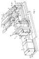
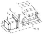
- FIG. 1 shows an exemplary embodiment of the device according to the invention.
- This essentially has a feed means 1, a stacking shaft 2 and a binding device 3.
- envelopes U are in a continuous stream from an envelope manufacturing or processing (filling, addressing, sorting etc.) device with a feed direction Z dem Stacking shaft 2 fed.
- the envelopes are collected in a stack S in the stacking shaft 2.
- the stack When the stack has reached a predetermined size, it is ejected from the stacking chute 2 with an ejection direction A, which is directed transversely to the feed direction Z, into the binding device 3, in which the stack S is tied together to form a bound stack G.
- the feeding means 1 is designed such that it feeds the envelopes U to be fed in a precisely defined position, advantageously held at least on the trailing edge. This is advantageously, as shown in the figure, a double conveyor belt, the envelopes to be fed being clamped between the two belts 11.1 and 11.2. However, it can also be, for example, a conveyor belt with clamps or a similar means of transport.
- the feed means opens into the stacking shaft 2 at the top, advantageously on the broad side thereof.
- the stacking shaft 2 has a support surface 21 and a front and a rear guide means 22 and 23, which are arranged transversely to the feed direction Z. Furthermore, on a third side, the stacking shaft has an ejection means 24 arranged parallel to the feed direction Z. The ejection means 24 is arranged to be displaceable in the ejection direction A (transverse to the feed direction Z) such that it can be moved between the front and the rear guide means (22 and 23) in the ejection direction A for ejecting a stack S. On the fourth side (ejection side), the stacking chute 2 is open for ejecting the finished stack (as shown) or is designed with guide means which can be removed accordingly for ejection.
- the front and rear guide means 22 and 23 of the stacking shaft extend as far as possible in one piece to the binding device 3 and in this extension take over the lateral guidance of the stack S during the ejection.
- the support surface 21 of the stacking shaft 2 also extends (advantageously in one piece) into the region of the binding device. It does not act as a means of transport, but as a sliding surface over which the stack S is pushed when it is ejected.
- the bearing surface 21 therefore advantageously has an absolutely flat and as fine a surface as possible; for example, it exists Made of high-gloss polished stainless steel or another slippery material.
- an auxiliary support surface 25 is arranged therein, for example in the form of a support fork, as shown in the figure.
- the auxiliary support surface 25 is arranged such that it can be moved in a substantially horizontal direction, advantageously in the feed direction Z, in the stacking shaft 2 and can be removed again in the opposite direction.
- the function of the auxiliary support surface is to be described in detail in connection with FIGS. 2a to 2h.
- a front and a rear stop 22.1 and 23.1 are attached above the auxiliary support surface in the feed direction Z and have the same orientation as the front and the rear guide means 22 and 23.
- the front and the rear stops 22.1 and 23.1 can, for example, be shown on the front in this case and the rear guide means 22 and 23 are integrally formed.
- the ejection means 24 is designed in terms of height such that it can be moved through under the auxiliary support surface 25.
- the binding device 3 corresponds essentially to a known binding device. It advantageously has only one binding point 31 with a press beam, plus a front stop 32 and a conveying means 33.
- the conveying means 33 is, for example, a conveyor belt which, on the side of the binding point 31 facing away from the stacking shaft 2, represents a support surface and means of transport for the bound stacks. If necessary, the conveying means can also be supplemented on the side of the binding point 31 facing the stacking shaft 2 by corresponding further auxiliary belts or rollers which adjoin the support surface 21 or are arranged laterally therefrom. It must simply be ensured that one of the ejection means 24 is in the binding position pushed stack can be moved by the conveyor 33 after binding.
- the ejection means 24 can, for example, as shown, have the shape of an ejection fork, which is arranged displaceably in corresponding slots in the support surface 21.
- the ejection fork occupies two extreme positions: a stacking position 24.1 and an ejection position 24.2.
- the ejection means 24 moves from the stacking position 24.1 into the ejection position 24.2.
- the ejection fork is advantageously moved back to the stacking position 24.1 in the same way. However, it can also be moved back into the stacking position 24.1 in another way, for example under the stacking shaft or past the stacking shaft.
- the ejection means 24 is advantageously slightly spaced from the stack S, so that products that are shifted slightly laterally do not come into conflict with it.
- it can also be used as a lateral guide means of the stacking shaft, in particular together with a second lateral guide means on the ejection side of the stacking shaft.
- the two lateral guide means are then at a distance from one another which corresponds exactly to the width of the envelopes to be stacked, and they are arranged symmetrically to the feed means 1.
- the front stop 32 of the binding device 3 serves for the vertical alignment of the envelopes of a stack in the binding position. This stop is designed in such a way that it can be moved away laterally, for example, to convey the bound stack G away.
- the simplest variant of the device according to the invention has only one binding point 31. If the stacks are to be bound in the middle (only one binding position of the stack relative to the binding point 31), the control of the removal means 33 can be directly coupled to the control of the ejection means 24 will. If the stacks are to be provided with two wraps running parallel to one another (two binding positions of the stack relative to the binding point 31), the conveying means 33 must be controlled in such a way that it promotes a bound stack before it is effectively transported away into a second binding position. Of course, binding devices with two parallel binding sites or binding devices for producing crossed wraps can also be used.
- the center lines of the feed (arrow Z) and the ejection (arrow A) are centered on a plan of the device cross the stacking shaft at a right angle, keep.
- the positions of the front and rear guide means 22 and 23 and of the front and rear stops 22.1 and 23.1 are set to adapt to the expansion of the envelopes in the feed direction Z, the opening point of the feed means 1 in the stacking shaft 2 also advantageously being adjusted.
- This is realized, for example, in the case of guide means which are molded or fastened to one another and have a corresponding stop, in that the two deflection rollers 12.1 and 12.2 of the double conveyor belt are coupled to the rear guide means 23 or stop 23.1 and are displaced therewith.
- they can be guided, for example, on their return runs via corresponding rollers which can be displaced in a substantially vertical direction (not shown).
- the two positions 24.1 and 24.2 of the ejection means 24 and the position of the front stop 32 are set accordingly.
- the three positions to be set are advantageously coupled to one another in such a way that a single setting action is sufficient for this.
- positions 24.1 and 24.2 are shifted the same distance to the left (in the figure) and stop 32 by the same distance to the right (in the figure).
- the movement of the conveyor 33 is not dependent on the format of the envelopes.
- all stacks are either wrapped in the middle (only one binding position) or are given two wraps with a constant distance from one another (two binding positions). If the distance between the two parallel wraps should be different depending on the envelope format, positions 24.1 and 24.2 and stop 32 must be adjustable independently of one another.
- the control of the removal means 33 must be adjustable, which of course makes the device considerably more complex.
- the feed means 1 can be part of the device delivering the envelopes.
- Such a feed means must also be designed such that it holds the envelopes in a precisely defined position at least at their trailing edge at least in the region of the mouth into the stacking shaft.
- the envelopes can be conveyed one after the other with or without spacing from one another or overlapping one another (scale flow).
- Another embodiment of the device according to the invention has two binding devices, one being arranged on each side of the stacking shaft and processing every other stack. Such an embodiment has more capacity.
- the ejection means does not have to be moved back from the ejection position to the stacking position, because the ejection position of the ejection means for a stack for one binding device is at the same time the stacking position of the same ejection means for a next stack for the other binding device.
- FIG. 1 Another embodiment of the device according to the invention differs from that shown in FIG. 1 in that the feed is essentially the same as the ejection.
- the envelopes are advantageously guided with a shorter edge against the narrow side of the stacking shaft.
- the ejection means can be moved in the same direction as the auxiliary support surface.
- the special advantages of the device according to the invention are that it is very compact.
- the feed means 1 needs a minimal or actually no length and the binding device 3 is arranged directly next to the stacking shaft 2.
- the auxiliary support surface 25 can be guided into the stacking shaft 2 from one side.
- the guide means 22 and 23 of the stacking shaft are also guide means for the ejection. For a double wrapping of the stack, only one binding point 31 has to be provided.
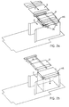
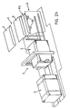
- FIGS. 2a to 2h now show the method according to the invention in various stages.
- the device corresponds to the embodiment which was described in connection with FIG. 1, but is no longer shown completely for a better overview.
- FIG. 2a shows the feeding of the envelopes U by the feeding means (1, FIG. 1), not shown, in the feeding direction Z.
- the auxiliary support surface 25 is positioned above the stacking shaft 2. Since the level of the auxiliary support surface is only slightly below the mouth of the feed means, the envelopes do not fall onto the auxiliary support surface 25 or onto other envelopes lying thereon, but are stacked on top of it by the feed means.
- An auxiliary stack HS is formed on the auxiliary support surface 25. When stacked, the envelopes are aligned in the feed direction Z by the front stop (not shown, 22.1, FIG. 1) and have a fairly exact position transversely to the feed direction thanks to the leading of the trailing edge by the feed means.
- a complete auxiliary stack HS comprises a predetermined number n (for example 10) envelopes and thus represents a "product" with better fall characteristics than a single envelope, since it is heavier than a single envelope with the same area.
- FIG. 2b shows the case of the auxiliary stack HS in the stacking shaft, which is triggered by removing the auxiliary stacking surface 25 when a predetermined number n (for example 10) of envelopes are stacked on the auxiliary supporting surface 25.
- the auxiliary support surface is advantageously removed from the stacking shaft counter to the feed direction Z (as shown).
- the auxiliary stack HS is held in position by the rear stop (not shown, 23.1, FIG. 1).
- the auxiliary support surface could also be moved out of the stacking shaft in the feed direction Z, the auxiliary stack being held in position by the front stop.
- the movement of the auxiliary support surface from the stacking shaft should be completed as soon as possible as soon as the last envelope of the auxiliary stack has been piled up.
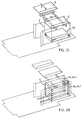
- Figure 2c shows the return movement of the auxiliary support surface 25 after the fall of the auxiliary stack HS in the stacking shaft 2. This return movement must be completed, at the latest when the trailing edge of the first envelope of the next auxiliary stack leaves the feed means.
- This return movement in the feed direction Z advantageously takes place at at least the same speed as the feeding of the envelopes.
- FIG. 2d shows a predetermined number m (for example 6) auxiliary stacks HS in the stacking shaft, which form a whole stack S. This can now be pushed out.
- m for example 6
- Figure 2e shows the ejection process.
- the stack S is pushed into a binding position in which the envelopes of the stack are aligned in the ejection direction A by the front stop 32.
- the ejection means 24 must be moved back into its stack position 24.1 (FIG. 2d) before the first auxiliary stack HS for the next stack is finished.
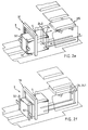
- FIG. 2f shows the stacking chute ready for receiving a next stack, while the stack S that has just been ejected is pressed and wrapped in the binding device (first binding position).
- the front stop 32 is removed from the path of the bound stack (as shown) and the conveying means (33, FIG. 1) is activated in such a way that it conveys the bound stack into a second binding position.
- FIG. 2g shows the stack S which has already been bound once in the second binding position.
- the second loop must be completed before the next stack in stacking shaft 2 is finished and has to be ejected.
- FIG. 2h shows the ejection of the next stack from the stacking shaft 2 and the simultaneous removal of the bound stack G from the binding device, for example.
- an envelope is layered on an auxiliary stack HS every 0.2 seconds. Approximately the same amount of time is available to move the auxiliary support surface away from the stacking shaft and also to reposition it.
- the formation of an auxiliary stack HS of, for example, 10 envelopes U takes 2 seconds. The same time is available to eject a stack and to position the ejection means in the stack position again.
- the formation of a stack S of, for example, 12 auxiliary stacks (120 envelopes) takes 24 seconds. This period of time is available to bind the stack (in the case of two wraps, therefore approx. 12 seconds per wrapping) and to convey it out of the binding device. From this example of an implementation of the method according to the invention it can be seen that the necessary movements of device parts (ejection means, conveying means, binding device) can be realized with known drives and transmission means.
- the device according to the invention processes a regular, continuous flow of envelopes, such as is supplied, for example, from a device that produces envelopes, it can be controlled purely on a cycle basis, that is to say the control of the auxiliary support surface, the ejection means, the binder and the means of conveyance are carried out by a common cycle correlated with each other.
- a regular flow of envelopes such as might arise from a sorting machine, must be fitted with sensor means, for example to determine the height of the auxiliary stack or to count the envelopes fed, the measuring pulses of which are used to control the movement of the auxiliary stack surface. All other movements must be correlated with this control or realized with the help of additional sensory means.
- the device according to the invention can also be controlled in such a way that each stack has an individual size that is dependent on other parameters.
- the size of the auxiliary stack is advantageously kept constant, so that the smallest stack consists of only one auxiliary stack.
Landscapes
- Engineering & Computer Science (AREA)
- Mechanical Engineering (AREA)
- Basic Packing Technique (AREA)
- Packaging Of Special Articles (AREA)
- Secondary Cells (AREA)
- Pile Receivers (AREA)
Abstract
Description
Die Erfindung liegt auf dem Gebiete der Weiterverarbeitung von Erzeugnissen aus Papier und betrifft ein Verfahren und eine Vorrichtung gemäss den entsprechenden unabhängigen Patentansprüchen, mit denen von Erzeugnissen aus Papier, insbesondere von Briefumschlägen mit oder ohne Inhalt gebundene Stapel hergestellt werden.The invention is in the field of further processing of paper products and relates to a method and a device according to the corresponding independent patent claims, with which stacks are made of paper products, in particular of envelopes with or without content.
Erzeugnisse aus Papier, wie beispielsweise Zeitungen, Hefte usw. fallen üblicherweise als kontinuierlicher Strom aus Herstellung oder Weiterverarbeitung an und werden dann oft für die Lagerung oder den Versand zu Stapeln gesammelt und zusammengebunden. Dazu fallen die Erzeugnisse in einen Stapelschacht, der bei gefalteten Produkten vorteilhafterweise einen Drehtisch aufweist. Wenn der Stapel eine vorgegebene Höhe erreicht hat, wird er aus dem Stapelschacht befördert und mittels eines Förderbandes zu einer Bindevorrichtung geführt, wo er zusammengepresst und mindestens einmal umschnürt wird.Paper products, such as newspapers, booklets, etc., are usually produced as a continuous stream from manufacture or further processing and are then often collected and bound in stacks for storage or shipping. For this purpose, the products fall into a stacking shaft which advantageously has a turntable for folded products. When the stack has reached a predetermined height, it is conveyed out of the stacking shaft and guided by means of a conveyor belt to a binding device, where it is pressed together and strapped at least once.
Derartige bekannte Methoden bedingen, dass der freie Fall der Erzeugnisse in den Stapelschacht derart kontrolliert abläuft, dass sie genau aufeinander zu liegen kommen. Ferner bedingen diese bekannten Methoden, dass die Stapel derart stabil sind, dass sie ohne zu desintegrieren transportiert werden können.Known methods of this type require that the free fall of the products into the stacking shaft is controlled in such a way that they approach one another exactly come to lie. Furthermore, these known methods require that the stacks are so stable that they can be transported without being disintegrated.
Es zeigt sich nun, dass die Fallcharakteristik der Erzeugnisse vom Verhältnis ihres Gewichtes zu ihrer flächigen Ausdehnung und von ihrer Steifheit abhängig ist und dass die Stabilität von Stapeln vor allem davon abhängig ist, ob die Erzeugnisse gefaltet sind und wie stark gepresst der Falz ist. Am einfachsten lassen sich beispielsweise buchartige Erzeugnisse stapeln, da sie eine regelmässige Dicke haben und relativ steif und schwer sind. Zeitungen müssen wegen des Falzes zu Kreuzstapeln gestapelt werden.It can now be seen that the fall characteristics of the products depend on the ratio of their weight to their areal extent and on their rigidity, and that the stability of stacks depends above all on whether the products are folded and how strongly the fold is pressed. The easiest way to stack book-like products, for example, is that they have a regular thickness and are relatively stiff and heavy. Newspapers have to be stacked in cross stacks because of the fold.
Es zeigt sich auch, dass Briefumschläge nicht leicht zu stapeln sind. Dies rührt daher, dass insbesondere leere Briefumschläge oder Briefumschläge mit wenig Inhalt leicht und wenig steif sind. Schwierigkeiten beim Stapeln können auch entstehen durch die beweglichen Klappen offener Briefumschläge und durch die Ränder von Sichtfenstern, an denen benachbarte Umschläge anstehen können.It also shows that envelopes are not easy to stack. This stems from the fact that empty envelopes or envelopes with little content are light and stiff. Stacking difficulties can also arise from the moveable flaps of open envelopes and the edges of viewing windows where adjacent envelopes can line up.
Gemäss dem Stande der Technik wird diesen Problemen begegnet, indem die Erzeugnisse nicht frei in einen Stapelschacht fallen gelassen sondern vielmehr auf den Stapel aufgeschoben werden, was dann möglich ist, wenn die Höhendifferenz zwischen Stapeloberseite und Zuführung sehr klein ist. Damit diese Höhendifferenz während des ganzen Stapelvorganges klein gehalten werden kann, wird üblicherweise die Stapelfläche, auf der die Erzeugnisse aufgestapelt werden, während dem Stapelvorgang korreliert mit dem Wachsen der Stapelhöhe gegen unten bewegt. Stapelvorrichtungen, die nach dieser Methode arbeiten, sind beispielsweise bekannt aus den Publikationen EP-A-0133945 und US-A-4977827.According to the prior art, these problems are countered by not dropping the products freely into a stacking shaft, but rather pushing them onto the stack, which is possible if the height difference between the top of the stack and the feeder is very small. So that this height difference can be kept small during the entire stacking process, the stacking surface on which the products are stacked is usually moved downwards during the stacking process, correlated with the increase in the stacking height. Stacking devices which operate according to this method are known, for example, from the publications EP-A-0133945 and US-A-4977827.
Es ist nun die Aufgabe der Erfindung, ein Verfahren aufzuzeigen, mit dem von Erzeugnissen aus Papier, insbesondere von schwierig stapelbaren derartigen Erzeugnissen, wie beispielsweise von Briefumschlägen mit Inhalt und Sichtfenstern, in möglichst einfacher Weise umschnürte Stapel erstellt werden können. Ebenso ist es die Aufgabe der Erfindung, eine Vorrichtung zur Durchführung des Verfahrens zu schaffen, wobei diese Vorrichtung im Vergleich zu bekannten Vorrichtungen zum Stapeln von Erzeugnissen aus Papier trotz ihrer Anwendbarkeit für schwierig stapelbare Erzeugnisse einfacher, weniger aufwendig und platzsparender sein soll. Die Vorrichtung soll einfach auf verschiedene Formate von Briefumschlägen umgestellt werden können.It is the object of the invention to demonstrate a method with which stacks of paper products, in particular of such difficult to stack products, such as envelopes with content and viewing windows, can be created in the simplest possible way. It is also the object of the invention to provide a device for carrying out the method, which device, in comparison to known devices for stacking paper products, is intended to be simpler, less complex and space-saving despite its applicability for products which are difficult to stack. The device should be able to be easily converted to different formats of envelopes.
Sie soll anwendbar sein für eine Leistung von bis zu ca. 20'000 Erzeugnissen pro Stunde.It should be applicable for an output of up to approx. 20,000 products per hour.
Diese Aufgabe wird gelöst durch das Verfahren und die Vorrichtung gemäss den entsprechenden, unabhängigen Patentansprüchen.This object is achieved by the method and the device according to the corresponding, independent patent claims.
Das erfindungsgemässe Verfahren und eine beispielhafte Ausführungsform der erfindungsgemässen Vorrichtung sollen mit Hilfe der folgenden Figuren beschrieben werden. Dabei zeigen:
- Figur 1
- eine beispielhafte Ausführungsform der erfindungsgemässen Vorrichtung;
- Figuren 2a bis 2h
- verschiedene Stadien im erfindungsgemässen Verfahren.
- Figure 1
- an exemplary embodiment of the device according to the invention;
- Figures 2a to 2h
- different stages in the process according to the invention.
Figur 1 zeigt eine beispielhafte Ausführungsform der erfindungsgemässen Vorrichtung. Diese weist im wesentlichen ein Zuführungsmittel 1 auf, einen Stapelschacht 2 und eine Bindevorrichtung 3. Mit Hilfe des Zuführungsmittels 1 werden Briefumschläge U in einem kontinuierlichen Strom von einer Briefumschläge herstellenden oder weiterverarbeitenden (füllen, adressieren, sortieren etc.) Vorrichtung mit einer Zuführrichtung Z dem Stapelschacht 2 zugeführt. Im Stapelschacht 2 werden die Briefumschläge zu einem Stapel S gesammelt. Wenn der Stapel eine vorgegebene Grösse erreicht hat, wird er aus dem Stapelschacht 2 ausgestossen mit einer Ausstossrichtung A, die quer zur Zuführrichtung Z gerichtet ist, in die Bindevorrichtung 3, in der der Stapel S zu einem gebundenen Stapel G zusammengeschnürt wird. FIG. 1 shows an exemplary embodiment of the device according to the invention. This essentially has a feed means 1, a
Das Zuführungsmittel 1 ist derart ausgestaltet, dass es die zuzuführenden Briefumschläge U in genau definierter Position, vorteilhafterweise mindestens an der nachlaufenden Kante festgehalten, zuführt. Es handelt sich dabei vorteilhafterweise, wie in der Figur dargestellt, um ein doppeltes Förderband, wobei die zuzuführenden Briefumschläge zwischen den beiden Bändern 11.1 und 11.2 eingeklemmt sind. Es kann sich aber auch beispielsweise um ein Förderband mit Klammern oder ein ähnliches Transportmittel handeln. Das Zuführungsmittel mündet oben in den Stapelschacht 2, vorteilhafterweise an dessen Breitseite.The feeding means 1 is designed such that it feeds the envelopes U to be fed in a precisely defined position, advantageously held at least on the trailing edge. This is advantageously, as shown in the figure, a double conveyor belt, the envelopes to be fed being clamped between the two belts 11.1 and 11.2. However, it can also be, for example, a conveyor belt with clamps or a similar means of transport. The feed means opens into the
Der Stapelschacht 2 weist eine Auflagefläche 21 auf und ein vorderes und ein hinteres Führungsmittel 22 und 23, die quer zur Zuführrichtung Z angeordnet sind. Ferner weist der Stapelschacht an einer dritten Seite ein parallel zur Zuführrichtung Z angeordnetes Ausstossmittel 24 auf. Das Ausstossmittel 24 ist derart in Ausstossrichtung A (quer zur Zuführrichtung Z) verschiebbar angeordnet, dass es zum Ausstossen eines Stapels S in Ausstossrichtung A zwischen dem vorderen und dem hinteren Führungsmittel (22 und 23) verschoben werden kann. Auf der vierten Seite (Ausstossseite) ist der Stapelschacht 2 für das Ausstossen des fertigen Stapels offen (wie dargestellt) oder mit entsprechend für das Ausstossen entfernbaren Führungsmitteln ausgestaltet.The
Das vordere und das hintere Führungsmittel 22 und 23 des Stapelschachtes reichen möglichst einstückig bis zur Bindevorrichtung 3 und übernehmen in dieser Verlängerung die seitliche Führung des Stapels S während dem Ausstossen. Auch die Auflagefläche 21 des Stapelschachtes 2 reicht (vorteilhafterweise einstückig) bis in den Bereich der Bindevorrichtung. Sie fungiert nicht als Transportmittel, sondern als Gleitfläche, über die der Stapel S beim Ausstossen geschoben wird. Die Auflagefläche 21 hat deshalb vorteilhafterweise eine absolut ebene und möglichst feine Oberfläche; sie besteht beispielsweise aus auf Hochglanz poliertem rostfreiem Stahl oder einem anderen gleitfreudigen Material.The front and rear guide means 22 and 23 of the stacking shaft extend as far as possible in one piece to the
Wenig unterhalb der Einmündung des Zuführungsmittels 1 in den Stapelschacht 2 ist in diesem eine Hilfsauflagefläche 25 angeordnet, beispielsweise in der Form einer Auflagegabel, wie in der Figur dargestellt. Die Hilfsauflagefläche 25 ist derart beweglich angeordnet, dass sie in im wesentlichen waagrechter Richtung, vorteilhafterweise in der Zuführrichtung Z in den Stapelschacht 2 eingeführt und in der entgegengesetzten Richtung wieder aus diesem entfernt werden kann. Die Funktion der Hilfsauflagefläche soll im Zusammenhang mit den Figuren 2a bis 2h detailliert beschrieben werden. Über der Hilfsauflagefläche sind in Zuführrichtung Z ein vorderer und ein hinterer Anschlag 22.1 und 23.1 angebracht, die dieselbe Ausrichtung haben wie das vordere und das hintere Führungsmittel 22 und 23. Der vordere und der hintere Anschlage 22.1 und 23.1 können dabei beispielsweise wie dargestellt an das vordere und das hintere Führungsmittel 22 und 23 angeformt sein. Das Ausstossmittel 24 ist höhenmässig derart ausgestaltet, dass es unter der Hilfsauflagefläche 25 durch bewegt werden kann.A little below the mouth of the feed means 1 in the
Die Bindevorrichtung 3 entspricht im wesentlichen einer bekannten Bindevorrichtung. Sie weist vorteilhafterweise nur eine Bindestelle 31 mit Pressbalken auf, dazu einen vorderen Anschlag 32 und ein Wegfördermittel 33. Das Wegfördermittel 33 ist beispielsweise ein Transportband, das auf der vom Stapelschacht 2 abgewandten Seite der Bindestelle 31 Auflagefläche und Transportmittel für die gebundenen Stapel darstellt. Das Wegfördermittel kann, wenn notwendig, auch auf der dem Stapelschacht 2 zugewandten Seite der Bindestelle 31 durch entsprechende weitere an die Auflagefläche 21 anschliessende oder seitlich von dieser angeordnete Hilfsbänder oder -rollen ergänzt werden. Es muss einfach sichergestellt werden, dass ein vom Ausstossmittel 24 in Bindeposition geschobener Stapel nach dem Binden vom Wegfördermittel 33 weiterbewegt werden kann.The
Das Ausstossmittel 24 kann beispielsweise, wie dargestellt, die Form einer Ausstossgabel haben, die in entsprechenden Schlitzen der Auflagefläche 21 verschiebbar angeordnet ist. Die Ausstossgabel nimmt dabei zwei Extrempositionen ein: eine Stapelposition 24.1 und eine Ausstossposition 24.2. Zum Ausstossen bewegt sich das Ausstossmittel 24 aus der Stapelposition 24.1 in die Ausstossposition 24.2. Die Ausstossgabel wird vorteilhafterweise auf demselben Weg wieder zurück in die Stapelposition 24.1 bewegt. Sie kann aber auch auf anderem Wege, beispielsweise unter dem Stapelschacht oder neben dem Stapelschacht vorbei in die Stapelposition 24.1 zurückbewegt werden.The ejection means 24 can, for example, as shown, have the shape of an ejection fork, which is arranged displaceably in corresponding slots in the
Das Ausstossmittel 24 ist in seiner Stapelposition 24.1 vorteilhafterweise leicht vom Stapel S beabstandet, damit leicht seitlich verschobene Erzeugnisse nicht damit in Konflikt geraten. Es kann aber auch zusätzlich als seitliches Führungsmittel des Stapelschachtes, insbesondere zusammen mit einem zweiten seitlichen Führungsmittel auf der Ausstosseite des Stapelschachtes eingesetzt werden. Die beiden seitlichen Führungsmittel haben dann einen Abstand voneinander, der genau der Breite der zu stapelnden Briefumschläge entspricht, und sie sind symmetrisch zum Zuführungsmittel 1 angeordnet.In its stacking position 24.1, the ejection means 24 is advantageously slightly spaced from the stack S, so that products that are shifted slightly laterally do not come into conflict with it. However, it can also be used as a lateral guide means of the stacking shaft, in particular together with a second lateral guide means on the ejection side of the stacking shaft. The two lateral guide means are then at a distance from one another which corresponds exactly to the width of the envelopes to be stacked, and they are arranged symmetrically to the feed means 1.
Der vordere Anschlag 32 der Bindevorrichtung 3 dient zur senkrechten Ausrichtung der Briefumschläge eines Stapels in der Bindeposition. Dieser Anschlag ist derart ausgestaltet, dass er für die Wegförderung des gebundenen Stapels G beispielsweise seitlich wegbewegt werden kann.The
Die einfachste Variante der erfindungsgemässen Vorrichtung besitzt, wie bereits erwähnt, nur eine Bindestelle 31. Sollen die Stapel damit mittig gebunden werden (nur eine Bindeposition des Stapels relativ zur Bindestelle 31), kann die Steuerung des Wegfördermittels 33 direkt mit der Steuerung des Ausstossmittels 24 gekoppelt werden. Sollen die Stapel mit zwei parallel zueinander verlaufenden Umschlingungen versehen werden (zwei Bindepositionen des Stapels relativ zur Bindestelle 31), muss das Wegfördermittel 33 derart gesteuert sein, dass es vor dem effektiven Wegfördern eines gebundenen Stapels diesen noch in eine zweite Bindeposition fördert. Selbstverständlich sind auch Bindevorrichtungen mit zwei parallelen Bindestellen oder Bindevorrichtungen zur Herstellung von gekreuzten Umschlingungen anwendbar.As already mentioned, the simplest variant of the device according to the invention has only one
Zur Anpassung der Vorrichtung an Briefumschläge verschiedener Formate, die sich sowohl in der Länge wie auch in der Breite voneinander unterscheiden können, werden die Mittellinien der Zuführung (Pfeil Z) und des Ausstossens (Pfeil A), die sich auf einem Grundriss der Vorrichtung im Mittelpunkt des Stapelschachtes rechtwinklig kreuzen, beibehalten.In order to adapt the device to envelopes of different formats, which can differ from one another both in length and in width, the center lines of the feed (arrow Z) and the ejection (arrow A) are centered on a plan of the device cross the stacking shaft at a right angle, keep.
Für eine Anpassung an die Ausdehnung der Briefumschläge in Zuführrichtung Z werden die Positionen des vorderen und hinteren Führungsmittels 22 und 23 und des vorderen und des hinteren Anschlages 22.1 und 23.1 eingestellt, wobei vorteilhafterweise auch die Einmündungsstelle des Zuführungsmittels 1 in den Stapelschacht 2 verstellt wird. Dies wird bei aneinandergeformten oder aneinander befestigtem Führungsmittel und entsprechendem Anschlag beispielsweise realisiert, indem die beiden Umlenkrollen 12.1 und 12.2 des doppelten Förderbandes mit dem hinteren Führungsmittel 23 bzw. Anschlag 23.1 gekoppelt sind und mit diesem verschoben werden. Zur Justierung der Länge der Förderbänder können diese beispielsweise auf ihrem Retourtrum über entsprechende, in im wesentlichen senkrechter Richtung verschiebbare Rollen geführt sein (nicht dargestellt).The positions of the front and rear guide means 22 and 23 and of the front and rear stops 22.1 and 23.1 are set to adapt to the expansion of the envelopes in the feed direction Z, the opening point of the feed means 1 in the stacking
Für eine Anpassung an die Ausdehnung der Briefumschläge quer zur Zuführrichtung Z werden die beiden Positionen 24.1 und 24.2 des Ausstossmittels 24 und die Position des vorderen Anschlages 32 entsprechend eingestellt. Vorteilhafterweise sind die drei einzustellenden Positionen derart miteinander gekoppelt, dass eine einzige Einstellungshandlung dafür genügt. Für eine Neueinstellung für kleinere Umschläge werden die Positionen 24.1 und 24.2 um dieselbe Strecke nach links (in der Figur) und der Anschlag 32 um dieselbe Strecke nach rechts (in der Figur) verschoben. Die Bewegung des Wegfördermittels 33 ist in diesem Fall nicht abhängig vom Format der Briefumschläge. Mit einer derart einstellbaren Vorrichtung werden alle Stapel entweder mittig umschlungen (nur eine Bindeposition) oder erhalten zwei Umschlingungen mit einem gleichbleibenden Abstand voneinander (zwei Bindepositionen). Soll der Abstand der zwei parallelen Umschlingungen je nach Umschlagsformat verschieden sein, müssen die Positionen 24.1 und 24.2 und der Anschlag 32 unabhängig voneinander einstellbar sein. Ebenso muss die Steuerung des Wegfördermittels 33 einstellbar sein, was die Vorrichtung natürlich beträchtlich aufwendiger macht.To adapt to the expansion of the envelopes transversely to the feed direction Z, the two positions 24.1 and 24.2 of the ejection means 24 and the position of the
In einer weiteren Ausführungsform der erfindungsgemässen Vorrichtung kann das Zuführungsmittel 1 ein Teil der die Umschläge liefernden Vorrichtung sein. Auch ein solches Zuführungsmittel muss derart ausgestaltet sein, dass es die Briefumschläge mindestens im Bereiche der Mündung in den Stapelschacht mindestens an ihrer nachlaufenden Kante in einer genau definierten Position hält.In a further embodiment of the device according to the invention, the feed means 1 can be part of the device delivering the envelopes. Such a feed means must also be designed such that it holds the envelopes in a precisely defined position at least at their trailing edge at least in the region of the mouth into the stacking shaft.
In der Zuführung können die Briefumschläge einzeln hintereinander mit oder ohne Abstand voneinander oder aber sich gegenseitig überlappend (Schuppenstrom) gefördert werden.In the feeder, the envelopes can be conveyed one after the other with or without spacing from one another or overlapping one another (scale flow).
Eine weitere Ausführungsform der erfindungsgemässen Vorrichtung weist zwei Bindevorrichtungen auf, wobei je eine auf jeder Seite des Stapelschachtes angeordnet ist und jeden zweiten Stapel verarbeitet. Eine derartige Ausführungsform hat mehr Kapazität. Insbesondere muss das Ausstossmittel nicht von der Ausstossposition in die Stapelposition zurückbewegt werden, denn die Ausstossposition des Ausstossmittels für einen Stapel für die eine Bindevorrichtung ist gleichzeitig die Stapelposition desselben Ausstossmittels für einen nächsten Stapel für die andere Bindevorrichtung.Another embodiment of the device according to the invention has two binding devices, one being arranged on each side of the stacking shaft and processing every other stack. Such an embodiment has more capacity. In particular, the ejection means does not have to be moved back from the ejection position to the stacking position, because the ejection position of the ejection means for a stack for one binding device is at the same time the stacking position of the same ejection means for a next stack for the other binding device.
Eine weitere Ausführungsform der erfindungsgemässen Vorrichtung unterscheidet sich dadurch von der in der Figur 1 dargestellten, dass die Zuführung im wesentlichen gleich verläuft wie das Ausstossen. Die Briefumschläge werden in diesem Falle vorteilhafterweise mit einer kürzeren Kante voran gegen die Schmalseite des Stapelschachtes geführt. Das Ausstossmittel ist in diesem Falle in derselben Richtung verschiebbar wie die Hilfsauflagefläche.Another embodiment of the device according to the invention differs from that shown in FIG. 1 in that the feed is essentially the same as the ejection. In this case, the envelopes are advantageously guided with a shorter edge against the narrow side of the stacking shaft. In this case, the ejection means can be moved in the same direction as the auxiliary support surface.
Die speziellen Vorteile der erfindungsgemässen Vorrichtung liegen darin, dass sie sehr kompakt ist. Das Zuführungsmittel 1 braucht eine minimale oder eigentlich keine Länge und die Bindevorrichtung 3 ist unmittelbar neben dem Stapelschacht 2 angeordnet. Die Hilfsauflagefläche 25 kann von einer Seite in den Stapelschacht 2 geführt werden. Die Führungsmittel 22 und 23 des Stapelschachts sind gleichzeitig Führungsmittel für das Ausstossen. Auch für eine doppelte Umschlingung des Stapels muss nur eine Bindestelle 31 vorgesehen werden.The special advantages of the device according to the invention are that it is very compact. The feed means 1 needs a minimal or actually no length and the
Figuren 2a bis 2h zeigen nun das erfindungsgemässe Verfahren in verschiedenen Stadien. Die Vorrichtung entspricht der Ausführungsform, die im Zusammenhang mit der Figur 1 beschrieben wurde, ist aber für eine bessere Übersicht nicht mehr vollständig dargestellt. FIGS. 2a to 2h now show the method according to the invention in various stages. The device corresponds to the embodiment which was described in connection with FIG. 1, but is no longer shown completely for a better overview.
Figur 2a zeigt die Zuführung der Briefumschläge U durch das nicht dargestellte Zuführungsmittel (1, Figur 1) in Zuführrichtung Z. Die Hilfsauflagefläche 25 ist über dem Stapelschacht 2 positioniert. Da das Niveau der Hilfsauflagefläche nur wenig unterhalb der Einmündung des Zuführungsmittels liegt, fallen die Briefumschläge nicht auf die Hilfsauflagefläche 25 oder auf darauf liegende andere Briefumschläge, sondern werden vom Zuführungsmittel darauf geschichtet. Es bildet sich auf der Hilfsauflagefläche 25 ein Hilfsstapel HS. Die Briefumschläge werden bei der Aufschichtung durch den vorderen Anschlag (nicht dargestellt, 22.1, Figur 1) in Zuführrichtung Z ausgerichtet und haben quer zur Zuführrichtung dank der Führung der nachlaufenden Kante durch das Zuführungsmittel eine ziemlich exakte Position. Ein kompletter Hilfsstapel HS umfasst eine vorgegebene Anzahl n (beispielsweise 10) Briefumschläge und stellt dadurch ein "Erzeugnis" mit einer besseren Fallcharakteristik dar als ein einzelner Briefumschlag, da er bei gleicher flächiger Ausdehnung schwerer ist als ein einzelner Briefumschlag. FIG. 2a shows the feeding of the envelopes U by the feeding means (1, FIG. 1), not shown, in the feeding direction Z. The
Figur 2b zeigt den Fall des Hilfsstapels HS in den Stapelschacht, der durch Entfernen der Hilfsstapelfläche 25 ausgelöst wird, wenn eine vorgegebene Anzahl n (bspw. 10) von Briefumschlägen auf die Hilfsauflagefläche 25 aufgeschichtet sind. Die Hilfsauflagefläche wird vorteilhafterweise entgegen der Zuführrichtung Z (wie dargestellt) vom Stapelschacht entfernt. Der Hilfsstapel HS wird dabei vom hinteren Anschlag (nicht dargestellt, 23.1, Figur 1) in seiner Position gehalten. Die Hilfsauflagefläche könnte auch in der Zuführrichtung Z aus dem Stapelschacht bewegt werden, wobei der Hilfsstapel vom vorderen Anschlag in Position gehalten wird. Die Bewegung der Hilfsauflagefläche aus dem Stapelschacht soll möglichst abgeschlossen sein, sobald der letzte Briefumschlag des Hilfsstapels aufgeschichtet ist. FIG. 2b shows the case of the auxiliary stack HS in the stacking shaft, which is triggered by removing the
Figur 2c zeigt die Rückbewegung der Hilfsauflagefläche 25 nach dem Fall des Hilfsstapels HS in den Stapelschacht 2. Diese Rückbewegung muss vollständig ausgeführt sein, spätestens wenn die nachlaufende Kante des ersten Briefumschlages des nächsten Hilfsstapels das Zuführungsmittel verlässt. Vorteilhafterweise erfolgt diese Rückbewegung in Zuführrichtung Z mit mindestens derselben Geschwindigkeit wie die Zuführung der Briefumschläge. Figure 2c shows the return movement of the
Figur 2d zeigt im Stapelschacht eine vorgegebene Anzahl m (beispielsweise 6) Hilfsstapel HS, die einen ganzen Stapel S bilden. Dieser kann jetzt ausgestossen werden. FIG. 2d shows a predetermined number m (for example 6) auxiliary stacks HS in the stacking shaft, which form a whole stack S. This can now be pushed out.
Figur 2e zeigt den Ausstossvorgang. Bei diesem wird durch Bewegung des Ausstossmittels 24 in Ausstossrichtung A in die Ausstossposition 24.2 der Stapel S in eine Bindeposition geschoben, in der die Briefumschläge des Stapels durch den vorderen Anschlag 32 in Ausstossrichtung A ausgerichtet werden. Das Ausstossmittel 24 muss in seine Stapelposition 24.1 (Figur 2d) zurückbewegt sein, bevor der erste Hilfsstapel HS für den nächsten Stapel fertiggestellt ist. Figure 2e shows the ejection process. In this case, by moving the ejection means 24 in the ejection direction A into the ejection position 24.2, the stack S is pushed into a binding position in which the envelopes of the stack are aligned in the ejection direction A by the
Figur 2f zeigt den Stapelschacht wieder bereit für die Aufnahme eines nächsten Stapels, während der eben ausgestossene Stapel S in der Bindevorrichtung (erste Bindeposition) gepresst und umschlungen wird. Sobald die Umschlingung fertig ist, wird der vordere Anschlag 32 aus dem Wegförderweg des gebundenen Stapels entfernt (wie dargestellt) und das Wegfördermittel (33, Figur 1) derart aktiviert, dass es den gebunden Stapel in eine zweite Bindeposition fördert. FIG. 2f shows the stacking chute ready for receiving a next stack, while the stack S that has just been ejected is pressed and wrapped in the binding device (first binding position). As soon as the wrapping is finished, the
Figur 2g zeigt den bereits einmal gebundenen Stapel S in der zweiten Bindeposition. Die zweite Umschlingung muss abgeschlossen sein, bevor der nächste Stapel im Stapelschacht 2 fertig ist und ausgestossen werden muss. FIG. 2g shows the stack S which has already been bound once in the second binding position. The second loop must be completed before the next stack in stacking
Figur 2h zeigt das Ausstossen des nächsten Stapels aus dem Stapelschacht 2 und das beispielsweise gleichzeitige Wegfördern des gebundenen Stapels G aus der Bindevorrichtung. FIG. 2h shows the ejection of the next stack from the stacking
Bei einer Leistung von 18'000 Briefumschlägen pro Stunde wird alle 0,2 Sekunden ein Briefumschlag auf einen Hilfsstapel HS geschichtet. Etwa dieselbe Zeitspanne steht zur Verfügung, um die Hilfsauflagefläche vom Stapelschacht wegzubewegen, und auch, um sie wieder zu positionieren. Die Bildung eines Hilfsstapels HS von bspw. 10 Briefumschlägen U dauert 2 Sek. Dieselbe Zeit steht zur Verfügung, um einen Stapel auszustossen und das Ausstossmittel wieder in Stapelposition zu positionieren. Die Bildung eines Stapels S von bspw. 12 Hilfsstapeln (120 Briefumschläge) dauert 24 Sek. Diese Zeitspanne steht zur Verfügung, um den Stapel zu binden (bei zwei Umschlingungen also ca. 12 Sek. pro Umschlingung) und ihn aus der Bindevorrichtung wegzufördern. Aus diesem Beispiel für eine Durchführung des erfindungsgemässen Verfahrens ist ersichtlich, dass die notwendigen Bewegungen von Vorrichtungsteilen (Ausstossmittel, Wegfördermittel, Bindevorrichtung) mit bekannten Antrieben und Übertragungsmitteln realisiert werden können.With an output of 18,000 envelopes per hour, an envelope is layered on an auxiliary stack HS every 0.2 seconds. Approximately the same amount of time is available to move the auxiliary support surface away from the stacking shaft and also to reposition it. The formation of an auxiliary stack HS of, for example, 10 envelopes U takes 2 seconds. The same time is available to eject a stack and to position the ejection means in the stack position again. The formation of a stack S of, for example, 12 auxiliary stacks (120 envelopes) takes 24 seconds. This period of time is available to bind the stack (in the case of two wraps, therefore approx. 12 seconds per wrapping) and to convey it out of the binding device. From this example of an implementation of the method according to the invention it can be seen that the necessary movements of device parts (ejection means, conveying means, binding device) can be realized with known drives and transmission means.
Verarbeitet die erfindungsgemässe Vorrichtung einen regelmässigen, kontinuierlichen Strom von Briefumschlägen, wie er beispielsweise aus einer Briefumschläge herstellenden Vorrichtung zugeführt wird, kann sie rein taktmässig gesteuert werden, das heisst die Steuerung der Hilfsauflagefläche, des Ausstossmittels, des Bindemittels und des Wegfördermittels sind durch einen gemeinsamen Takt miteinander korreliert. Verarbeitet die Vorrichtung aber einen unregelmässigen Strom von Briefumschlägen, wie er beispielsweise aus einer Sortiermaschine anfallen könnte, müssen sensorische Mittel eingebaut werden, um beispielsweise die Höhe des Hilfsstapels zu bestimmen oder die zugeführten Umschläge zu zählen, deren Messimpulse für die Steuerung der Bewegung der Hilfsstapelfläche verwendet werden. Alle anderen Bewegungen müssen mit dieser Steuerung korreliert oder mit Hilfe von zusätzlichen sensorischen Mitteln realisiert werden.If the device according to the invention processes a regular, continuous flow of envelopes, such as is supplied, for example, from a device that produces envelopes, it can be controlled purely on a cycle basis, that is to say the control of the auxiliary support surface, the ejection means, the binder and the means of conveyance are carried out by a common cycle correlated with each other. Processes the device An irregular flow of envelopes, such as might arise from a sorting machine, must be fitted with sensor means, for example to determine the height of the auxiliary stack or to count the envelopes fed, the measuring pulses of which are used to control the movement of the auxiliary stack surface. All other movements must be correlated with this control or realized with the help of additional sensory means.
Selbstverständlich kann die erfindungsgemässe Vorrichtung auch derart gesteuert werden, dass jeder Stapel eine individuelle, von anderen Parametern abhängige Grösse hat. Die Grösse des Hilfsstapels wird dabei vorteilhafterweise konstant gehalten, sodass der kleinste Stapel aus nur einem Hilfsstapel besteht.Of course, the device according to the invention can also be controlled in such a way that each stack has an individual size that is dependent on other parameters. The size of the auxiliary stack is advantageously kept constant, so that the smallest stack consists of only one auxiliary stack.
Claims (19)
- Method for producing bound stacks of paper products (U), particularly those products which are difficult to stack such as envelopes with a content and viewing windows, the method having the following method stages:a. continuous supply in a supply direction (Z) of the products (U) in a continuous stream to a supply position at the upper edge of a stacking shaft (2), at least the trailing edge of each product being held in a clearly defined position,b. formation of an auxiliary stack (HS) by stacking a predetermined number n of products on an auxiliary bearing surface (25) positioned below the supply position in the stacking shaft, the products being positioned at the front and rear by a front and a rear stop (22.1, 23.1) at least in the supply direction (Z) and the position of the auxiliary bearing surface (25) in the stacking shaft remains unchanged,c. formation of a stack (S) by removing the auxiliary bearing surface (25) and allowing the auxiliary stack (HS) to drop onto a bearing surface (21) located below the auxiliary bearing surface in the stacking shaft (2), the auxiliary stack (HS) being guided by guidance means (22, 23) at least on the sides at right angles to the supply direction (Z) and in which the position of the bearing surface remains unchanged,d. repositioning the auxiliary bearing surface (25) and formation of a further auxiliary stack,e. repetition of stages b. to d. until a predetermined number m of auxiliary stacks has been collected in the stacking shaft (2),f. ejection of the stack (S) in an ejection direction (A) into a binding position during the formation of the next auxiliary stack (HS), the stack (S) being moved by an ejecting means (24) over the bearing surface (21) and laterally guided by the guidance means (22, 23), and repositioning of the ejecting means (24),g. looping the stack in the binding position for producing a bound stack (G) during the formation of the next stack in the stacking shaft (2),h. conveying away of the stack from the binding position prior to the ejection of the next stack.
- Method according to claim 1, characterized in that the products (U) are supplied with their longer edge at right angles to the supply direction (Z) and the supply direction (Z) is directed at right angles to the ejection direction (A).
- Method according to one of the claims 1 or 2, characterized in that, after looping in a first binding position, the stack is conveyed into a second binding position and looped a second time.
- Method according to one of the claims 1 or 2, characterized in that the stack is looped crosswise or parallel.
- Method according to one of the claims 1 to 4, characterized in that the products are supplied jammed between two conveyor belts (11.1 and 11.2).
- Method according to one of the claims 1 to 5, characterized in that the auxiliary bearing surface (25) is removed from the stacking shaft counter to the supply direction (Z) and is repositioned in said supply direction (Z).
- Method according to claim 6, characterized in that the auxiliary bearing surface (25) is moved at at least the same speed into the stacking shaft with which the products are moved by the supply means (1) into said stacking shaft (2).
- Method according to one of the claims 1 to 7, characterized in that during ejection, the ejecting means (24) are moved over an ejection path from a stacking position (24.1) into an ejection position (24.2) and is moved back over the ejection path for repositioning in its stacking position (24.1).
- Method according to one of the claims 1 to 7, characterized in that during ejection the ejecting means (24) is moved over an ejection path from a stacking position (24.1) into an ejection position (24.2) and that it is moved back into the stacking position (24.1) over a path differing from the ejection path.
- Method according to one of the claims 1 to 9, characterized in that the products (U) of a stack (S) in the binding position are oriented in the ejection direction (A) by a front stop (32).
- Method according to one of the claims 1 to 10, characterized in that n is approximately 10 and m is at least 1.
- Method according to one of the claims 1 to 11, characterized in that the stacks are ejected alternately in two mutually opposite ejection directions and that the ejection position (24.2) of the ejecting means (24) relative to one binding device is the stacking position (24.1) of the ejecting means relative to the other binding device.
- Method according to claim 1, characterized in that the products (U) are supplied with their shorter edge at right angles to the supply direction (Z) and that the ejection direction (A) is substantially the same as the supply direction (Z).
- Apparatus for producing stacks of paper products having a supply means (1) for supplying a continuous stream of products (U) in a supply direction (Z), a stacking shaft (2) for forming a stack (S) and a binding device (3), in whicha. the binding device (3) is located in an ejection direction (A) from the stacking shaft (2) and the ejection direction (A) is substantially at right angles to the supply direction (Z),b. the supply means (1) has holding means with which at least the trailing edge of the products (U) is held in a clearly defined position,c. at the upper wide side of the stacking shaft (2) the supply means (1) issues into the latter,d. the stacking shaft (2) has a bearing surface (21) extending against the binding device (2) and invariably positioned relative to the height of the stacking shaft and has front and rear guidance means (22, 23) arranged at right angles to the supply direction (Z) and extending counter to the binding device (3),e. an ejecting member positioned parallel to the supply direction (Z) for ejecting the stack (S) from the stacking shaft (2) displaceably arranged in the ejection direction (A) in such a way that it is movable from a stacking position (24.1) into an ejection position (24.2),f. additionally in its upper area below the issuing point of the supply means (1), the stacking shaft (2) has an auxiliary bearing surface (25), which is so displaceably driven that it is movable substantially in the supply direction (Z) into the stacking shaft (2) and is removable from the latter counter to the supply direction, its position in the stacking shaft being invariable relative to its height,g. above the auxiliary bearing surface (25) a front and a rear stop (22.1, 23.1) is oriented on the front and rear guidance means (22, 23),h. the ejecting means (24) has a height such that it can be moved under the auxiliary bearing surface (25),i. the binding device (3) has a binding point (31), as well as conveying away means (33) connected to the bearing surface (21) in the vicinity of the binding point and a front stop (32) orienting the products of a stack in the binding position, which is displaceable in such a way that it can be moved into and removed out of the conveying away path of the stack.
- Apparatus according to claim 14, characterized in that the front stop (22.1) is shaped onto the front guidance means (22) and the rear stop (23.1) onto the rear guidance means (23).
- Apparatus according to claim 14 or 15, characterized in that the front and rear guidance means (22, 23) for adapting the apparatus to envelopes having a different extension in the supply direction (Z) are displaceably arranged parallel to said supply direction.
- Apparatus according to claim 16, characterized in that the supply means (1) is coupled to the rear stop (22.1) in such a way that its issuing point into the stacking shaft is displaceable with the stop.
- Apparatus according to one of the claims 14 to 17, characterized in that the two positions (24.1, 24.2) of the ejecting means (24) and the position of the front stop (32) for adapting the apparatus to envelopes with different extensions at right angles to the supply direction (Z) can be displaced.
- Apparatus according to one of the claims 14 to 17, characterized in that the supply means (1) form part of a device for producing or further processing the products connected upstream of the apparatus.
Applications Claiming Priority (2)
| Application Number | Priority Date | Filing Date | Title |
|---|---|---|---|
| CH3055/92 | 1992-09-30 | ||
| CH305592 | 1992-09-30 |
Publications (2)
| Publication Number | Publication Date |
|---|---|
| EP0591099A1 EP0591099A1 (en) | 1994-04-06 |
| EP0591099B1 true EP0591099B1 (en) | 1997-05-07 |
Family
ID=4247606
Family Applications (1)
| Application Number | Title | Priority Date | Filing Date |
|---|---|---|---|
| EP93810613A Expired - Lifetime EP0591099B1 (en) | 1992-09-30 | 1993-08-26 | Method and device for making tied stacks of paper products |
Country Status (5)
| Country | Link |
|---|---|
| EP (1) | EP0591099B1 (en) |
| AT (1) | ATE152684T1 (en) |
| DE (1) | DE59306378D1 (en) |
| DK (1) | DK0591099T3 (en) |
| ES (1) | ES2105196T3 (en) |
Cited By (2)
| Publication number | Priority date | Publication date | Assignee | Title |
|---|---|---|---|---|
| DE102008024599A1 (en) | 2008-05-21 | 2009-12-10 | WINKLER+DüNNEBIER AG | Apparatus for forming stacked packages |
| CN106628970A (en) * | 2016-11-18 | 2017-05-10 | 长兴海普机械科技有限公司 | Sorting and extruding device |
Families Citing this family (8)
| Publication number | Priority date | Publication date | Assignee | Title |
|---|---|---|---|---|
| US5617784A (en) * | 1995-10-05 | 1997-04-08 | Baldwin Technology Corporation | Apparatus for bundling, transporting, and feeding sheets |
| DE19743978B4 (en) * | 1997-10-06 | 2008-08-21 | Ssb Strapping Systeme Bindlach Gmbh | Device for transporting stacks |
| GB2386106A (en) * | 2002-03-05 | 2003-09-10 | Carrs Paper Ltd | Packaging a stack of paper for loading into a machine |
| FR2837793B1 (en) * | 2002-03-27 | 2004-08-27 | Gpv Navarre Diffusion | PACK OF PACKAGED ENVELOPES, METHOD AND DEVICE SUITABLE FOR PACKAGING |
| US7344021B2 (en) | 2004-10-14 | 2008-03-18 | Garnier Ponsonnet Vuillard | Package block of envelopes |
| CN106586066B (en) * | 2016-11-18 | 2019-03-29 | 浙江卓凡印刷有限公司 | A kind of carton arrangement auxiliary baling equipment |
| CN106672288B (en) * | 2016-11-18 | 2018-10-30 | 长兴海普机械科技有限公司 | A kind of packing collator with delivery device |
| CN108545252B (en) * | 2018-05-02 | 2020-05-05 | 江西金力永磁科技股份有限公司 | Fold material equipment |
Family Cites Families (6)
| Publication number | Priority date | Publication date | Assignee | Title |
|---|---|---|---|---|
| FR1448273A (en) * | 1965-06-24 | 1966-08-05 | Holweg Const Mec | Machine for bundling bags, envelopes, sheets or the like of paper or other material |
| GB1281757A (en) * | 1969-08-11 | 1972-07-12 | Yuji Fujishiro | Bundling printed sheets |
| DE2245505A1 (en) * | 1972-09-15 | 1974-03-21 | Metaverpa Nv | ROTARY DEVICE |
| EP0133945A1 (en) * | 1983-07-28 | 1985-03-13 | Harris Graphics Corporation | Signature handling apparatus |
| DE3705169A1 (en) * | 1987-02-18 | 1988-09-01 | Sesto Palamides | METHOD AND DEVICE FOR PACKING PRINTED PRODUCTS |
| US4977827A (en) * | 1989-01-17 | 1990-12-18 | Am International Incorporated | Signature handling apparatus |
-
1993
- 1993-08-26 DE DE59306378T patent/DE59306378D1/en not_active Expired - Fee Related
- 1993-08-26 EP EP93810613A patent/EP0591099B1/en not_active Expired - Lifetime
- 1993-08-26 DK DK93810613.5T patent/DK0591099T3/en active
- 1993-08-26 ES ES93810613T patent/ES2105196T3/en not_active Expired - Lifetime
- 1993-08-26 AT AT93810613T patent/ATE152684T1/en not_active IP Right Cessation
Cited By (3)
| Publication number | Priority date | Publication date | Assignee | Title |
|---|---|---|---|---|
| DE102008024599A1 (en) | 2008-05-21 | 2009-12-10 | WINKLER+DüNNEBIER AG | Apparatus for forming stacked packages |
| CN106628970A (en) * | 2016-11-18 | 2017-05-10 | 长兴海普机械科技有限公司 | Sorting and extruding device |
| CN106628970B (en) * | 2016-11-18 | 2019-05-10 | 江苏克诺斯精密材料有限公司 | A kind of arrangement pressurizing unit |
Also Published As
| Publication number | Publication date |
|---|---|
| ES2105196T3 (en) | 1997-10-16 |
| DE59306378D1 (en) | 1997-06-12 |
| EP0591099A1 (en) | 1994-04-06 |
| DK0591099T3 (en) | 1997-08-25 |
| ATE152684T1 (en) | 1997-05-15 |
Similar Documents
| Publication | Publication Date | Title |
|---|---|---|
| DE68924859T3 (en) | Feeding device for stacked workpieces. | |
| EP2139776B1 (en) | Device and method for handling flat objects, in particular nappies | |
| EP1472162A1 (en) | Positioning system | |
| DE3018894C2 (en) | Device for forming upright packages of flat folding box blanks | |
| DE4300002A1 (en) | Overlapping print article processing appts. e.g. for books - separates and selectively deflects articles into holders using programmable controller receiving signals from counter and speed sensor | |
| DE4027247A1 (en) | METHOD AND DEVICE FOR PROMOTING BANDEROLE PURPOSES TO A (CIGARETTE) PACK | |
| EP0371219B1 (en) | Device for piling continuously arriving, substantially quadrangular printed products | |
| EP1991484B1 (en) | Apparatus and method for forming stacks of flat products | |
| EP1099632B1 (en) | Method and device for feeding flat articles to their individual separation | |
| EP0591099B1 (en) | Method and device for making tied stacks of paper products | |
| EP0309745B1 (en) | Device for stacking printed products continuously arriving in an imbricated product stream | |
| DE19533086A1 (en) | Method and device for stacking flat products, in particular printed products | |
| WO1982000995A1 (en) | Device for stacking overlapping plane products,particularly printed products | |
| DE4330427A1 (en) | Method and device for forming stacks of goods, in particular cookies | |
| DE3929364C1 (en) | ||
| EP2399853A2 (en) | Transport device for flat products | |
| EP1350750A1 (en) | Method and device for forming piles of continuously delivered, flat ojects | |
| DE102017223709A1 (en) | Device and method for handling food portions with a rotating device | |
| DE1436064C3 (en) | Device for gathering folded sheets into a book block | |
| EP0529204A1 (en) | Apparatus for conveying plates towards a deep drawing machine | |
| CH699389B1 (en) | Temporary storage device and stacking unit with temporary storage device. | |
| EP0328875A2 (en) | Method and apparatus for separating flat articles | |
| DE69919477T2 (en) | Method and machine for packaging a group of articles | |
| EP1219558A2 (en) | Method and device for collating flat obects | |
| EP1303452B1 (en) | Method and device for the stacking of flat objects |
Legal Events
| Date | Code | Title | Description |
|---|---|---|---|
| PUAI | Public reference made under article 153(3) epc to a published international application that has entered the european phase |
Free format text: ORIGINAL CODE: 0009012 |
|
| AK | Designated contracting states |
Kind code of ref document: A1 Designated state(s): AT BE CH DE DK ES FR GB IT LI NL SE |
|
| 17P | Request for examination filed |
Effective date: 19940910 |
|
| 17Q | First examination report despatched |
Effective date: 19960214 |
|
| GRAG | Despatch of communication of intention to grant |
Free format text: ORIGINAL CODE: EPIDOS AGRA |
|
| GRAH | Despatch of communication of intention to grant a patent |
Free format text: ORIGINAL CODE: EPIDOS IGRA |
|
| ITF | It: translation for a ep patent filed | ||
| GRAH | Despatch of communication of intention to grant a patent |
Free format text: ORIGINAL CODE: EPIDOS IGRA |
|
| GRAH | Despatch of communication of intention to grant a patent |
Free format text: ORIGINAL CODE: EPIDOS IGRA |
|
| GRAA | (expected) grant |
Free format text: ORIGINAL CODE: 0009210 |
|
| AK | Designated contracting states |
Kind code of ref document: B1 Designated state(s): AT BE CH DE DK ES FR GB IT LI NL SE |
|
| REF | Corresponds to: |
Ref document number: 152684 Country of ref document: AT Date of ref document: 19970515 Kind code of ref document: T |
|
| REG | Reference to a national code |
Ref country code: CH Ref legal event code: NV Representative=s name: FREI PATENTANWALTSBUERO Ref country code: CH Ref legal event code: EP |
|
| GBT | Gb: translation of ep patent filed (gb section 77(6)(a)/1977) |
Effective date: 19970509 |
|
| REF | Corresponds to: |
Ref document number: 59306378 Country of ref document: DE Date of ref document: 19970612 |
|
| ET | Fr: translation filed | ||
| REG | Reference to a national code |
Ref country code: DK Ref legal event code: T3 |
|
| REG | Reference to a national code |
Ref country code: ES Ref legal event code: FG2A Ref document number: 2105196 Country of ref document: ES Kind code of ref document: T3 |
|
| PLBE | No opposition filed within time limit |
Free format text: ORIGINAL CODE: 0009261 |
|
| STAA | Information on the status of an ep patent application or granted ep patent |
Free format text: STATUS: NO OPPOSITION FILED WITHIN TIME LIMIT |
|
| 26N | No opposition filed | ||
| REG | Reference to a national code |
Ref country code: GB Ref legal event code: IF02 |
|
| PGFP | Annual fee paid to national office [announced via postgrant information from national office to epo] |
Ref country code: AT Payment date: 20020729 Year of fee payment: 10 |
|
| PGFP | Annual fee paid to national office [announced via postgrant information from national office to epo] |
Ref country code: BE Payment date: 20020808 Year of fee payment: 10 |
|
| PGFP | Annual fee paid to national office [announced via postgrant information from national office to epo] |
Ref country code: ES Payment date: 20020809 Year of fee payment: 10 |
|
| PGFP | Annual fee paid to national office [announced via postgrant information from national office to epo] |
Ref country code: GB Payment date: 20030724 Year of fee payment: 11 |
|
| PGFP | Annual fee paid to national office [announced via postgrant information from national office to epo] |
Ref country code: SE Payment date: 20030728 Year of fee payment: 11 |
|
| PGFP | Annual fee paid to national office [announced via postgrant information from national office to epo] |
Ref country code: FR Payment date: 20030729 Year of fee payment: 11 Ref country code: NL Payment date: 20030729 Year of fee payment: 11 |
|
| PG25 | Lapsed in a contracting state [announced via postgrant information from national office to epo] |
Ref country code: AT Free format text: LAPSE BECAUSE OF NON-PAYMENT OF DUE FEES Effective date: 20030826 |
|
| PG25 | Lapsed in a contracting state [announced via postgrant information from national office to epo] |
Ref country code: ES Free format text: LAPSE BECAUSE OF NON-PAYMENT OF DUE FEES Effective date: 20030827 |
|
| PG25 | Lapsed in a contracting state [announced via postgrant information from national office to epo] |
Ref country code: BE Free format text: LAPSE BECAUSE OF NON-PAYMENT OF DUE FEES Effective date: 20030831 |
|
| BERE | Be: lapsed |
Owner name: *METAVERPA B.V. Effective date: 20030831 |
|
| PG25 | Lapsed in a contracting state [announced via postgrant information from national office to epo] |
Ref country code: GB Free format text: LAPSE BECAUSE OF NON-PAYMENT OF DUE FEES Effective date: 20040826 |
|
| PG25 | Lapsed in a contracting state [announced via postgrant information from national office to epo] |
Ref country code: SE Free format text: LAPSE BECAUSE OF NON-PAYMENT OF DUE FEES Effective date: 20040827 |
|
| REG | Reference to a national code |
Ref country code: ES Ref legal event code: FD2A Effective date: 20030827 |
|
| REG | Reference to a national code |
Ref country code: CH Ref legal event code: NV Representative=s name: FERAG AG |
|
| PG25 | Lapsed in a contracting state [announced via postgrant information from national office to epo] |
Ref country code: NL Free format text: LAPSE BECAUSE OF NON-PAYMENT OF DUE FEES Effective date: 20050301 |
|
| EUG | Se: european patent has lapsed | ||
| GBPC | Gb: european patent ceased through non-payment of renewal fee |
Effective date: 20040826 |
|
| PG25 | Lapsed in a contracting state [announced via postgrant information from national office to epo] |
Ref country code: FR Free format text: LAPSE BECAUSE OF NON-PAYMENT OF DUE FEES Effective date: 20050429 |
|
| NLV4 | Nl: lapsed or anulled due to non-payment of the annual fee |
Effective date: 20050301 |
|
| REG | Reference to a national code |
Ref country code: FR Ref legal event code: ST |
|
| PGFP | Annual fee paid to national office [announced via postgrant information from national office to epo] |
Ref country code: DK Payment date: 20080814 Year of fee payment: 16 Ref country code: DE Payment date: 20080822 Year of fee payment: 16 Ref country code: CH Payment date: 20080820 Year of fee payment: 16 |
|
| PGFP | Annual fee paid to national office [announced via postgrant information from national office to epo] |
Ref country code: IT Payment date: 20080826 Year of fee payment: 16 |
|
| REG | Reference to a national code |
Ref country code: CH Ref legal event code: PL |
|
| REG | Reference to a national code |
Ref country code: DK Ref legal event code: EBP |
|
| PG25 | Lapsed in a contracting state [announced via postgrant information from national office to epo] |
Ref country code: LI Free format text: LAPSE BECAUSE OF NON-PAYMENT OF DUE FEES Effective date: 20090831 Ref country code: CH Free format text: LAPSE BECAUSE OF NON-PAYMENT OF DUE FEES Effective date: 20090831 |
|
| PG25 | Lapsed in a contracting state [announced via postgrant information from national office to epo] |
Ref country code: DK Free format text: LAPSE BECAUSE OF NON-PAYMENT OF DUE FEES Effective date: 20090831 Ref country code: DE Free format text: LAPSE BECAUSE OF NON-PAYMENT OF DUE FEES Effective date: 20100302 |
|
| PG25 | Lapsed in a contracting state [announced via postgrant information from national office to epo] |
Ref country code: IT Free format text: LAPSE BECAUSE OF NON-PAYMENT OF DUE FEES Effective date: 20090826 |