EP0835722B1 - Apparatus and method for producing a plastic lens - Google Patents
Apparatus and method for producing a plastic lens Download PDFInfo
- Publication number
- EP0835722B1 EP0835722B1 EP97117491A EP97117491A EP0835722B1 EP 0835722 B1 EP0835722 B1 EP 0835722B1 EP 97117491 A EP97117491 A EP 97117491A EP 97117491 A EP97117491 A EP 97117491A EP 0835722 B1 EP0835722 B1 EP 0835722B1
- Authority
- EP
- European Patent Office
- Prior art keywords
- block material
- tool
- processing
- grinding
- smoothing
- Prior art date
- Legal status (The legal status is an assumption and is not a legal conclusion. Google has not performed a legal analysis and makes no representation as to the accuracy of the status listed.)
- Expired - Lifetime
Links
Images
Classifications
-
- B—PERFORMING OPERATIONS; TRANSPORTING
- B23—MACHINE TOOLS; METAL-WORKING NOT OTHERWISE PROVIDED FOR
- B23Q—DETAILS, COMPONENTS, OR ACCESSORIES FOR MACHINE TOOLS, e.g. ARRANGEMENTS FOR COPYING OR CONTROLLING; MACHINE TOOLS IN GENERAL CHARACTERISED BY THE CONSTRUCTION OF PARTICULAR DETAILS OR COMPONENTS; COMBINATIONS OR ASSOCIATIONS OF METAL-WORKING MACHINES, NOT DIRECTED TO A PARTICULAR RESULT
- B23Q3/00—Devices holding, supporting, or positioning work or tools, of a kind normally removable from the machine
- B23Q3/155—Arrangements for automatic insertion or removal of tools, e.g. combined with manual handling
- B23Q3/157—Arrangements for automatic insertion or removal of tools, e.g. combined with manual handling of rotary tools
-
- B—PERFORMING OPERATIONS; TRANSPORTING
- B24—GRINDING; POLISHING
- B24B—MACHINES, DEVICES, OR PROCESSES FOR GRINDING OR POLISHING; DRESSING OR CONDITIONING OF ABRADING SURFACES; FEEDING OF GRINDING, POLISHING, OR LAPPING AGENTS
- B24B13/00—Machines or devices designed for grinding or polishing optical surfaces on lenses or surfaces of similar shape on other work; Accessories therefor
- B24B13/0031—Machines having several working posts; Feeding and manipulating devices
- B24B13/0037—Machines having several working posts; Feeding and manipulating devices the lenses being worked by different tools, e.g. for rough-grinding, fine-grinding, polishing
-
- B—PERFORMING OPERATIONS; TRANSPORTING
- B24—GRINDING; POLISHING
- B24B—MACHINES, DEVICES, OR PROCESSES FOR GRINDING OR POLISHING; DRESSING OR CONDITIONING OF ABRADING SURFACES; FEEDING OF GRINDING, POLISHING, OR LAPPING AGENTS
- B24B45/00—Means for securing grinding wheels on rotary arbors
- B24B45/003—Accessories therefor
-
- B—PERFORMING OPERATIONS; TRANSPORTING
- B29—WORKING OF PLASTICS; WORKING OF SUBSTANCES IN A PLASTIC STATE IN GENERAL
- B29D—PRODUCING PARTICULAR ARTICLES FROM PLASTICS OR FROM SUBSTANCES IN A PLASTIC STATE
- B29D11/00—Producing optical elements, e.g. lenses or prisms
- B29D11/00932—Combined cutting and grinding thereof
- B29D11/00942—Combined cutting and grinding thereof where the lens material is mounted in a support for mounting onto a cutting device, e.g. a lathe, and where the support is of machinable material, e.g. plastics
Definitions
- This invention relates to an apparatus for and a method of the production of plastic lens substrate, as per the preamble of claims 1 and 11.
- An example of such an apparatus and method is disclosed in EP 453 627 A.
- a plastic block material suited as a plastic lens substrate for use in eyeglasses has been produced from processing of one of its two surfaces by means of three processing steps, i.e., grinding, smoothing and polishing.
- the plastic block material (referred to hereinafter as the block material) denotes a thick-walled lens having already been processed on a convex side but being still required to be processed so as to gain a lens thickness and a concave side as desired.
- the block material is a so-called semi-finished lens. Details as regards each of the process steps stated above will be described below.
- the grinding step is intended to cut one selected surface of the block material (hereunder called a lens forming surface) in such a manner that a desired radius is attained on the lens forming surface.
- a diamond wheel is employed which is known as a cup-shaped tool having diamond particles electro-deposited on its grinding face.
- the diamond wheel is caused to axially rotate and then brought into movable contact on the particulate diamond-deposited face with the lens forming surface of the block material, while a coolant is being applied to the lens forming surface.
- the coolant is usually water or an aqueous solution in which a rust preventive, an antifoaming agent and the like are contained.
- the smoothing step follows upon completion of the grinding step.
- the smoothing step is intended to render fine or smooth the lens forming surface of the block material, which lens forming surface has been cut to a predetermined radius but with some surface roughness through the grinding step.
- the smoothing step is effected by use of an aluminum tray provided with a face having a radius to correspond to that defined on the lens forming surface of the block material. Disposed adhesively over that tray face is a sheet-like polishing medium commonly called a smoothing pad for exclusive use in such a step of smoothing.
- the aluminum tray mentioned here is known as a processing tray.
- the processing tray is manipulated to rotate such that during application of a coolant, the polishing medium is allowed to slidably contact with the lens forming surface of the block material.
- the block material processed to have reduced surface roughness on the lens forming surface through the smoothing step is thereafter subjected to the polishing step as a finishing operation.
- the polishing step contemplates imparting greater fineness or smoothness to the lens forming surface having undergone processing via the smoothing step. Also in the polishing step, use is made of an aluminum tray of the type stated previously in connection with the smoothing step having a face radially shaped to fit the lens forming surface of the block material.
- a polishing medium (a polishing pad, for example) to be adhesively mounted on the aluminum tray is softer in nature and smaller in mesh than that employed in the smoothing step.
- the polishing step is achieved by bringing the resulting processing tray into slidable contact with the lens forming surface, while a polishing liquid is being applied to the latter.
- the block material has been processed on its lens forming surface by means of the three process steps as discussed above. In each such step, each individual exclusive processing apparatus is employed.
- the conventional production method needs a separate processing apparatus so as to carry out each process step of grinding, smoothing and polishing of a plastic block material. Such method, therefore, leads to an increase in equipment cost and in floor space. Additionally, many different processing trays are needed to cope with varying radii desired to be processed in both of the smoothing and polishing steps. Those processing trays cause burdens of time and cost for their preparation. Furthermore, the radii to be processed are dependent upon the formulations of lenses that are variable with the requests to be made by individual users. A large number of radii are required to be satisfied in order to tailor users' needs. However, because of a great expenditure of time and effort to prepare processing trays, inventories are necessary for those trays of a wide variety of kinds. This literally results in added storage space and increased cost investment in advance. The foregoing problems create an obstacle to improved lens productivity and to saved production cost.
- the conventional production method using processing trays requires that the trays be brought into slidable contact with a lens forming surface of a plastic block material with the result that possible processing is limited to a spherical lens and a toric lens.
- the plastic lens generator comprises a rotatable chuck for rotating an optical lens blank, two drive systems and a cutter.
- a computer control is operably associated with the drive systems for coordinating displacement of the associated chuck and cutter for causing a selected curvature to be generated on the blank.
- the present invention has been made to solve or eliminate the aforementioned problems experienced in the production method of the prior art.
- a pad adhesively attached to the processing tray for use in each of the smoothing and polishing steps must be replaced with a new one every time one block material is completely processed. Releasing of a spent pad and attachment of a fresh pad have been found to be tedious with a lot of effort and manpower.
- Still another finding is that it is inconvenient to find a processing tray of a desirable radius out of a wide variety of inventories.
- the desired processing tray would sometimes be tried in vain to find when the same is being used in another step. In such instance, some waiting time would be spent until the processing tray is made available. This is responsible for a decline in production efficiency.
- the plastic block material may preferably be chosen from one of thermoplastic resins and thermosetting resins.
- the thermoplastic resins may be cellulose resins (such as celluloid, cellulose acetate, cellulose propionate, and cellulose butyrate), polyamide resins including aliphatic polyamide (such as 6-nylon, 6,6-nylon, and 12-nylon) and aromatic polyamide, polyolefins (such as ABS resin, AS resin, polystyrene, polyethylene and polypropylene), vinyl resins (such as polyvinyl chloride, polyvinylidene chloride, ethylene-vinyl acetate copolymer, and polyvinyl alcohol), saturated polyesters (such as polyacetal, polycarbonate, polyethylene terephthalate, and polybutylene terephthalate), aromatic polyesters, polyether ketone, polyether ether ketone, polysulfone, polyether sulfone, polyether imide, polyarylate, polymethyl pentene,
- thermosetting resins may be epoxy resin, unsaturated polyester, thermosetting polyurethane, polyimide, polymer of diethylene glycol bis-allycarbonate (CR-39), copolymer of bisphenol A or halogenated bisphenol A and diacrylate di(meth)acrylate, copolymer of bisphenol A or halogenated bisphenol A and urethane-modified di(meta)acrylate, or copolymer of a diacrylate compound or vinyl benzyl alcohol and an unsaturated thiol compound.
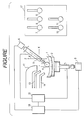
- the drawing is a schematic elevation illustrative of the apparatus of the invention.
- a plastic block material 1 is mounted in place on a retainer 2 located for retaining a processing material to be processed.
- the block material 1 is placed on its convex side to adhesively fit the retainer 2 with use of a metal alloy of a low melting point.
- One side of the retainer 2 is designed to retain the processing material or block material 1, and the other side is securely attached to an axis that is coupled with a manipulator 3.
- the manipulator 3 acts to permit rotation of the retainer 2, and to this end, a motor or the like can be used.
- the retainer 2 is movable in directions of X and/or Y and/or Z, and these movements are achievable by the action of an actuator 15. Though shown connected to the retainer 2 in the drawing, the actuator 15 may be united with the manipulator 3 in such a manner that the latter is allowed to move together with the manipulator 3.
- Each of the manipulator 3 and the actuator 15 communicates with a control unit 16.
- the control unit 16 controls the manipulator 3, thereby controlling the number of revolution and the speed of revolution in regard to the retainer 2 and also the on-off operation of the manipulator 3. Additionally, the control unit 16 controls the actuator 15, thereby controlling the X and/or Y and/or Z directions of movement, the distance of movement, the speed of movement and the on-off operation in regard to the retainer 2.
- a computer is preferably used as the control unit 16. While in arrangement illustrated in the drawing, both of the manipulator 3 and the actuator 15 are connected to the one single control unit 16, separate control units may be arranged with respect to the manipulator 3 and the actuator 15.
- a holder 5 disposed for holding a processing tool is positioned toward the side of the retainer 2 disposed for retaining the processing material or block material 1.
- the holder 5 is provided at one end thereof with a location for holding the processing tool and at the other opposite end with a manipulator 6.
- the manipulator 6 operates to enable axial rotation of the processing tool. For this operation, a motor, a high-frequency motor, an air spindle or the like can be put to use.
- the holder 5 is coupled with the actuator 15.
- the actuator 15 acts on the processing tool in respect of the X and/or Y and/or Z directions of movement, the distance of movement and the on-off operation as well as the inclination ( ⁇ ) of movement.
- the manipulator 6 is also coupled to the control unit 16.
- the control unit 16 acts to control the manipulator 6, thereby controlling the processing tool in respect of the X and/or Y and/or Z directions of movement, the distance of movement, the speed of movement and the on-off operation as well as the inclination ( ⁇ ) of movement and the on-off operation of inclination.
- a computer-aided unit can be used. If the axis of ⁇ is set at a degree of zero, then the processing tool actually works only at a region near to its top with consequential failure to attain a sufficient circumferential speed which could arise from rotation of the processing tool. Also adversely, such tool is liable to involve clogging or like inconvenience. For those reasons, the axis of ⁇ should be inclined in the practice of the present invention.
- those controls made via the manipulator 6 are performed by use of one control unit.
- individual control units may be arranged to effect the respective controls.
- the actuator 15 and the control unit 16 are arranged to actuate both of the retainer 2 and the holder 5 and to control the manipulators 3, 6 of these constituent parts.
- the actuator 15 and the control unit 16 may be held in separately operative relation to each other.
- an exhaust duct 12 Disposed upwardly laterally of the block material 1 are an exhaust duct 12, a coolant-supplying hose 13 and a polishing liquid-supplying hose 14.
- Duct exhaust, coolant supply and liquid supply are all effected by use of a computer-aided motor which is capable of making the on-off operations and of controlling the extents of exhaust and supply.
- a storage unit 17 for storing the processing tools is located adjacent to the tool holder 5.
- the storage unit 17 is constructed to accommodate a plurality of processing tools 7, 8, 9, 10, 11 of varying shapes, hardnesses and dimensions for adaptability to each of process steps of grinding, smoothing and polishing.
- the holder 5 moves to arrive at the storage unit 17, thus selecting any necessary tool for subsequent processing. The operator's discretion is used in that selection.
- Suitable processing tools for use in the grinding step include a ball end mill and an end mill, and eligible materials include diamond and an ultra-hard material.
- Suitable processing tools for use in the smoothing step are chosen from an electro-deposited whetstone and a resin-bonded whetstone.
- Suitable processing tools for use in the polishing step are chosen from a felt buff, a silicone rubber and a brush.
- the holder 5 and the retainer 2 may be allowed to move in the directions of X and/or Y and/or Z by movement of either one or both of the two constituent parts. Furthermore, the processing tool and the retainer 2 may be allowed to rotate by rotation of either one or both of the two parts.
- rotation of the block material and/or the processing tool movement of the block material and/or the processing tool, exchange of processing tools, local exhaust, and supply of the coolant and the polishing liquid are achieved by means of computer control.
- fixing and removal of the block material are required to be effected only once.
- Lens processing from grinding to polishing is automatically feasible with use of one set of production apparatus.
- rotation of the block material and/or the lens, rotation of the tool, and movement of the tool are conducted through numerical control aided by a computer so that lens surfaces such as an aspherical surface, a progressive surface, a combination of aspherical and toric surfaces and so on can be processed at will, which lens surfaces have been found unattainable by the method of the prior art.
- thermoplastic resins may be cellulose resins (such as celluloid, cellulose acetate, cellulose propionate, and cellulose butyrate), polyamide resins including aliphatic polyamide (such as 6-nylon, 6,6-nylon, and 12-nylon) and aromatic polyamide, polyolefins (such as ABS resin, AS resin, polystyrene, polyethylene and polypropylene), vinyl resins (such as polyvinyl chloride, polyvinylidene chloride, ethylene-vinyl acetate copolymer, and polyvinyl alcohol), saturated polyesters (such as polyacetal, polycarbonate, polyethylene terephthalate, and polybutylene terephthalate), aromatic polyesters, polyether ketone, polyether ether ketone, polysulfone, polyether sulfone, polyether
- thermosetting resins may be epoxy resin, unsaturated polyester, thermosetting polyurethane, polyimide, polymer of diethylene glycol bis-allycarbonate (CR-39), copolymer of bisphenol A or halogenated bisphenol A and di(meth)acrylate, copolymer of bisphenol A or halogenated bisphenol A and urethane-modified di(meth)acrylate, or copolymer of a diacrylate compound or vinyl benzyl alcohol and an unsaturated thiol compound.
- the thermosetting resins include, in addition to heat-curable resins, photo-curable resins such as of an acrylic class and the like.
- a plastic block material was processed to produce a plastic lens substrate.
- a plastics-made semi-finished lens (a polymer of CR-39) that had been processed to define a convex surface thereon was fixed on a processing material retainer with the convex side directed downwardly.
- the term semi-finished lens is meant a lens substrate prepared for processing a concave side thereon on a custom-made basis and according to a certain specific lens formulation.
- the semi-finished lens is provided with a convex surface previously processed.
- a concave surface was processed with a radius of 100 mm in consideration of the lens formulation and the convex shape of the semi-finished lens.
- the cutter-carrying holder was caused to move in Z and X directions and to locate peripherally of the block material.
- the lens was rotated at a speed of 4 rpm and the tool at 5,000 rpm.
- the block material was thereafter stock-removed with exhaust to a depth of about 3.0 mm in the Z direction, while the X axis was displaced at a speed of 2.80 mm/min from the periphery of the block material to the central direction. While in displacement of the Z axis, a concave surface of 100 mm in radius was processed.
- a diamond-electrodeposited whetstone No. 120 (Item No. A3608, spherical shape of 6.0 mm in radius) manufactured by MINITOR Co., Ltd. was selected and mounted on the tool holder.
- the whetstone-carrying holder was caused to move in the Z and X directions and to locate peripherally of the block material. With the ⁇ axis inclined at a degree of 30, the tool was rotated at a speed of 5,000 rpm.
- the block material was then stock-removed to a depth of 0.05 mm in the Z direction during supplying of water as a coolant, while the X axis was moved at a speed of 0.08 mm/min from the periphery of the block material to the central direction. While in displacement of the Z axis, a concave surface of 100 mm in radius was processed.
- a felt buff of a soft type (Item No. E5518, spherical shape of 10 mm in radius) manufactured by MINITOR Co., Ltd. was selected and mounted on the tool holder.
- the buff-carrying holder was caused to move in the Z and X directions and to locate peripherally of the block material. With the ⁇ axis inclined at a degree of 30, the block material was rotated at a speed of 4 rpm and the processing tool at 5,000 rpm.
- the block material was then stock-removed to a depth of 0.005 mm in the Z direction during supplying as a polishing liquid of Polipla 103A commercially obtained from Fujimi Incorporated, while the X axis was moved at a speed of 36 mm/min from the periphery of the block material to the central direction. While in displacement of the Z axis, a concave surface of 100 mm in radius was processed.
- a plastic lens substrate which was provided with a toric surface thereon was produced.
- a plastic block material use was made of a semi-finished lens formed of the same material as in that tested in Example 1 and processed to define a convex surface of a given curvature. This semi-finished lens was placed on a processing material retainer.
- the radii of a concave surface were set at 100 mm in a first axis and at 75 mm in a second axis orthogonal to the first axis with the shape of the semi-finished lens and the lens formulation taken in view.
- the same processing tool as used for grinding in Example 1 was chosen and mounted on a tool holder.
- the processing tool was displaced at Z and X axes and located peripherally of the block material.
- the tool holder was inclined at a degree of 30 with respect to the perpendicular line extending from a lens forming surface of the semi-finished lens and then caused to rotate with such conditions as of 4 rpm of the lens and 5,000 rpm of the tool.
- the axis of Z was controlled to displace through the movement synchronized with the angle of rotation of the semi-finished lens such that a toric surface was processed.
- this angle of rotation is meant the angle of the toric surface specified in accordance with the lens formulation.
- Example 1 As regards subsequent process steps of smoothing and polishing, the procedures of Example 1 were followed except that curvatures were set to meet with the above requirements of the toric surface.
- processing may be effected by controlling displacement of the Z axis through the movement synchronized with the angle of rotation of the semi-finished lens, thereby meeting with those free curvatures programmed by a computer or the like.
- a substrate to be subjected to grinding is a semi-finished lens which has not been adjusted in its diameter.
- the semi-finished lens can be processed on its edge face according to a certain piece of information that is made obtainable by counting a processable diameter of a lens substrate from the shape of a lens ready for attachment to glasses. This processing is commonly called chamfering.
- the chamfered lens is of a circular shape.
- edging can be conducted prior to grinding.
- Processing tools for use in chamfering and edging may be those used for grinding. More desirably, however, a cylindrical processing tool may be used which is shaped to be straight at a portion disposed for contact with the end face of the semi-finished lens.
- the polishing step alone can be effected with use of a separate apparatus.
- chamfering, grinding and smoothing are effected in one and the same apparatus and polishing alone in a second apparatus.
- the same set of processing tools is applicable to grinding, smoothing and chamfering.
- the production method can effect grinding, smoothing and polishing with only one cycle of fixing and removal of a processing material, eventually contributing to shortened processing.
- the method according to the invention causes such steps to be performed in one and the same apparatus and hence leads to saved equipment cost and reduced floor space. Further, saved storage space and saved preparation cost are attainable for processing trays since the latter are not necessary in the practice of the invention. This gives rise to reduced production cost of the processing material.
- lens surfaces such as an aspherical surface, a progressive surface and the like are processable when desired, which lens surfaces have been found unattainable by the method of the prior art.
- the prior art method using processing trays makes it markedly difficult to process, because of the need for a larger number of processing trays, special lens formulations of more or less 10 diopters on a spherical surface and of more or less than 4 diopters on a toric surface.
- the apparatus according to the invention has no need for such trays and has found satisfactorily applicable to specific lens formulations.
Description
- This invention relates to an apparatus for and a method of the production of plastic lens substrate, as per the preamble of
claims 1 and 11. An example of such an apparatus and method is disclosed in EP 453 627 A. - Heretofore, a plastic block material suited as a plastic lens substrate for use in eyeglasses has been produced from processing of one of its two surfaces by means of three processing steps, i.e., grinding, smoothing and polishing. The plastic block material (referred to hereinafter as the block material) denotes a thick-walled lens having already been processed on a convex side but being still required to be processed so as to gain a lens thickness and a concave side as desired. The block material is a so-called semi-finished lens. Details as regards each of the process steps stated above will be described below.
- Firstly, the grinding step is intended to cut one selected surface of the block material (hereunder called a lens forming surface) in such a manner that a desired radius is attained on the lens forming surface. To this end, a diamond wheel is employed which is known as a cup-shaped tool having diamond particles electro-deposited on its grinding face. To conduct the grinding step, the diamond wheel is caused to axially rotate and then brought into movable contact on the particulate diamond-deposited face with the lens forming surface of the block material, while a coolant is being applied to the lens forming surface. Put to use as the coolant is usually water or an aqueous solution in which a rust preventive, an antifoaming agent and the like are contained.
- The smoothing step follows upon completion of the grinding step.
- The smoothing step is intended to render fine or smooth the lens forming surface of the block material, which lens forming surface has been cut to a predetermined radius but with some surface roughness through the grinding step. In the conventional practice, the smoothing step is effected by use of an aluminum tray provided with a face having a radius to correspond to that defined on the lens forming surface of the block material. Disposed adhesively over that tray face is a sheet-like polishing medium commonly called a smoothing pad for exclusive use in such a step of smoothing. The aluminum tray mentioned here is known as a processing tray. The processing tray is manipulated to rotate such that during application of a coolant, the polishing medium is allowed to slidably contact with the lens forming surface of the block material.
- The block material processed to have reduced surface roughness on the lens forming surface through the smoothing step is thereafter subjected to the polishing step as a finishing operation.
- The polishing step contemplates imparting greater fineness or smoothness to the lens forming surface having undergone processing via the smoothing step. Also in the polishing step, use is made of an aluminum tray of the type stated previously in connection with the smoothing step having a face radially shaped to fit the lens forming surface of the block material. A polishing medium (a polishing pad, for example) to be adhesively mounted on the aluminum tray is softer in nature and smaller in mesh than that employed in the smoothing step. The polishing step is achieved by bringing the resulting processing tray into slidable contact with the lens forming surface, while a polishing liquid is being applied to the latter.
- In the production of a plastic lens substrate, the block material has been processed on its lens forming surface by means of the three process steps as discussed above. In each such step, each individual exclusive processing apparatus is employed.
- To produce a plastic lens substrate for use in glasses, the present inventors have practiced the production apparatus and production method of the prior art, thereby processing a plastic block material. Consequently, these inventors have found that the conventional practice suffers from too long a period of time for processing.
- The conventional production method needs a separate processing apparatus so as to carry out each process step of grinding, smoothing and polishing of a plastic block material. Such method, therefore, leads to an increase in equipment cost and in floor space. Additionally, many different processing trays are needed to cope with varying radii desired to be processed in both of the smoothing and polishing steps. Those processing trays cause burdens of time and cost for their preparation. Furthermore, the radii to be processed are dependent upon the formulations of lenses that are variable with the requests to be made by individual users. A large number of radii are required to be satisfied in order to tailor users' needs. However, because of a great expenditure of time and effort to prepare processing trays, inventories are necessary for those trays of a wide variety of kinds. This literally results in added storage space and increased cost investment in advance. The foregoing problems create an obstacle to improved lens productivity and to saved production cost.
- Besides and disadvantageously, the conventional production method using processing trays requires that the trays be brought into slidable contact with a lens forming surface of a plastic block material with the result that possible processing is limited to a spherical lens and a toric lens.
- An alternative plastic lens generator, producing lenses without utilizing processing trays is disclosed in
EP 0 453 627. The plastic lens generator comprises a rotatable chuck for rotating an optical lens blank, two drive systems and a cutter. A computer control is operably associated with the drive systems for coordinating displacement of the associated chuck and cutter for causing a selected curvature to be generated on the blank. - Accordingly, the present invention has been made to solve or eliminate the aforementioned problems experienced in the production method of the prior art.
- To make a search for the grounds of those problems, the present inventors have processed a plastic block material with use of the production method and production apparatus of the prior art.
- It takes from one minute to several minutes to effect and finish each of those process steps including grinding, smoothing and polishing. The block material must be fixed and removed every time each such step is done with eventual need for tedious operation. To complete one cycle of the three process steps in processing one block material, it is of necessity that the block material be fixed thrice and removed thrice and that processing trays be mounted twice and dismantled twice. It has been found that fixing and removal of the block material as well as mounting and dismantling of the processing trays total up to ten times, thus inviting great effort and much manpower.
- Moreover, a pad adhesively attached to the processing tray for use in each of the smoothing and polishing steps must be replaced with a new one every time one block material is completely processed. Releasing of a spent pad and attachment of a fresh pad have been found to be tedious with a lot of effort and manpower.
- Still another finding is that it is inconvenient to find a processing tray of a desirable radius out of a wide variety of inventories. The desired processing tray would sometimes be tried in vain to find when the same is being used in another step. In such instance, some waiting time would be spent until the processing tray is made available. This is responsible for a decline in production efficiency.
- The facts noted above have now proved to cause added cost and diminished efficiency when a plastic lens is produced for custom-made glasses.
- In a first aspect of the present invention, there is provided an apparatus for the production of a plastic lens substrate as per claim 1.
- In a second aspect of the invention, there is provided a method of the production of a plastic lens substrate, as per
claim 11. - In each of the two aspects stated above, the plastic block material may preferably be chosen from one of thermoplastic resins and thermosetting resins. The thermoplastic resins may be cellulose resins (such as celluloid, cellulose acetate, cellulose propionate, and cellulose butyrate), polyamide resins including aliphatic polyamide (such as 6-nylon, 6,6-nylon, and 12-nylon) and aromatic polyamide, polyolefins (such as ABS resin, AS resin, polystyrene, polyethylene and polypropylene), vinyl resins (such as polyvinyl chloride, polyvinylidene chloride, ethylene-vinyl acetate copolymer, and polyvinyl alcohol), saturated polyesters (such as polyacetal, polycarbonate, polyethylene terephthalate, and polybutylene terephthalate), aromatic polyesters, polyether ketone, polyether ether ketone, polysulfone, polyether sulfone, polyether imide, polyarylate, polymethyl pentene, ionomer, liquid crystal polymer, polyimide, fluoropolymer, polyphenyl sulfide, modified polyphenylene oxide or thermoplastic polyurethane. The thermosetting resins may be epoxy resin, unsaturated polyester, thermosetting polyurethane, polyimide, polymer of diethylene glycol bis-allycarbonate (CR-39), copolymer of bisphenol A or halogenated bisphenol A and diacrylate di(meth)acrylate, copolymer of bisphenol A or halogenated bisphenol A and urethane-modified di(meta)acrylate, or copolymer of a diacrylate compound or vinyl benzyl alcohol and an unsaturated thiol compound.
- The accompanying drawing illustrates, in a schematic elevation, one preferred form of the production apparatus according to the present invention.
- The production apparatus of the present invention will now be described below.
- The drawing is a schematic elevation illustrative of the apparatus of the invention.
- A plastic block material 1 is mounted in place on a retainer 2 located for retaining a processing material to be processed. In this embodiment, the block material 1 is placed on its convex side to adhesively fit the retainer 2 with use of a metal alloy of a low melting point. One side of the retainer 2 is designed to retain the processing material or block material 1, and the other side is securely attached to an axis that is coupled with a manipulator 3. The manipulator 3 acts to permit rotation of the retainer 2, and to this end, a motor or the like can be used.
- The retainer 2 is movable in directions of X and/or Y and/or Z, and these movements are achievable by the action of an
actuator 15. Though shown connected to the retainer 2 in the drawing, theactuator 15 may be united with the manipulator 3 in such a manner that the latter is allowed to move together with the manipulator 3. - Each of the manipulator 3 and the
actuator 15 communicates with acontrol unit 16. Thecontrol unit 16 controls the manipulator 3, thereby controlling the number of revolution and the speed of revolution in regard to the retainer 2 and also the on-off operation of the manipulator 3. Additionally, thecontrol unit 16 controls theactuator 15, thereby controlling the X and/or Y and/or Z directions of movement, the distance of movement, the speed of movement and the on-off operation in regard to the retainer 2. In such instance, a computer is preferably used as thecontrol unit 16. While in arrangement illustrated in the drawing, both of the manipulator 3 and theactuator 15 are connected to the onesingle control unit 16, separate control units may be arranged with respect to the manipulator 3 and theactuator 15. - A
holder 5 disposed for holding a processing tool is positioned toward the side of the retainer 2 disposed for retaining the processing material or block material 1. Theholder 5 is provided at one end thereof with a location for holding the processing tool and at the other opposite end with a manipulator 6. The manipulator 6 operates to enable axial rotation of the processing tool. For this operation, a motor, a high-frequency motor, an air spindle or the like can be put to use. - The
holder 5 is coupled with theactuator 15. Here, the actuator 15 acts on the processing tool in respect of the X and/or Y and/or Z directions of movement, the distance of movement and the on-off operation as well as the inclination () of movement. - The manipulator 6 is also coupled to the
control unit 16. Thecontrol unit 16 acts to control the manipulator 6, thereby controlling the processing tool in respect of the X and/or Y and/or Z directions of movement, the distance of movement, the speed of movement and the on-off operation as well as the inclination () of movement and the on-off operation of inclination. To this end, a computer-aided unit can be used. If the axis of is set at a degree of zero, then the processing tool actually works only at a region near to its top with consequential failure to attain a sufficient circumferential speed which could arise from rotation of the processing tool. Also adversely, such tool is liable to involve clogging or like inconvenience. For those reasons, the axis of should be inclined in the practice of the present invention. - In the embodiment now described, those controls made via the manipulator 6 are performed by use of one control unit. When it is found desirable, individual control units may be arranged to effect the respective controls. On the other hand, the
actuator 15 and thecontrol unit 16 are arranged to actuate both of the retainer 2 and theholder 5 and to control the manipulators 3, 6 of these constituent parts. Theactuator 15 and thecontrol unit 16 may be held in separately operative relation to each other. - Disposed upwardly laterally of the block material 1 are an
exhaust duct 12, a coolant-supplyinghose 13 and a polishing liquid-supplyinghose 14. Duct exhaust, coolant supply and liquid supply are all effected by use of a computer-aided motor which is capable of making the on-off operations and of controlling the extents of exhaust and supply. - A
storage unit 17 for storing the processing tools is located adjacent to thetool holder 5. Thestorage unit 17 is constructed to accommodate a plurality ofprocessing tools holder 5 moves to arrive at thestorage unit 17, thus selecting any necessary tool for subsequent processing. The operator's discretion is used in that selection. - Suitable processing tools for use in the grinding step include a ball end mill and an end mill, and eligible materials include diamond and an ultra-hard material. Suitable processing tools for use in the smoothing step are chosen from an electro-deposited whetstone and a resin-bonded whetstone. Suitable processing tools for use in the polishing step are chosen from a felt buff, a silicone rubber and a brush.
- In implementing the present invention, the
holder 5 and the retainer 2 may be allowed to move in the directions of X and/or Y and/or Z by movement of either one or both of the two constituent parts. Furthermore, the processing tool and the retainer 2 may be allowed to rotate by rotation of either one or both of the two parts. - According to the production method rotation of the block material and/or the processing tool, movement of the block material and/or the processing tool, exchange of processing tools, local exhaust, and supply of the coolant and the polishing liquid are achieved by means of computer control. As a consequence, fixing and removal of the block material are required to be effected only once. Lens processing from grinding to polishing is automatically feasible with use of one set of production apparatus.
- Also advantageously, rotation of the block material and/or the lens, rotation of the tool, and movement of the tool are conducted through numerical control aided by a computer so that lens surfaces such as an aspherical surface, a progressive surface, a combination of aspherical and toric surfaces and so on can be processed at will, which lens surfaces have been found unattainable by the method of the prior art.
- The present invention is suitable for the processing of plastic materials. Suitable plastic materials especially for use as lens substrates in plastic glasses may preferably be selected from one of thermoplastic resins and thermosetting resins. The thermoplastic resins may be cellulose resins (such as celluloid, cellulose acetate, cellulose propionate, and cellulose butyrate), polyamide resins including aliphatic polyamide (such as 6-nylon, 6,6-nylon, and 12-nylon) and aromatic polyamide, polyolefins (such as ABS resin, AS resin, polystyrene, polyethylene and polypropylene), vinyl resins (such as polyvinyl chloride, polyvinylidene chloride, ethylene-vinyl acetate copolymer, and polyvinyl alcohol), saturated polyesters (such as polyacetal, polycarbonate, polyethylene terephthalate, and polybutylene terephthalate), aromatic polyesters, polyether ketone, polyether ether ketone, polysulfone, polyether sulfone, polyether imide, polyarylate, polymethyl pentene, ionomer, liquid crystal polymer, polyimide, fluoropolymer, polyphenyl sulfide, modified polyphenylene oxide or thermoplastic polyurethane. The thermosetting resins may be epoxy resin, unsaturated polyester, thermosetting polyurethane, polyimide, polymer of diethylene glycol bis-allycarbonate (CR-39), copolymer of bisphenol A or halogenated bisphenol A and di(meth)acrylate, copolymer of bisphenol A or halogenated bisphenol A and urethane-modified di(meth)acrylate, or copolymer of a diacrylate compound or vinyl benzyl alcohol and an unsaturated thiol compound. The thermosetting resins include, in addition to heat-curable resins, photo-curable resins such as of an acrylic class and the like.
- In this example, a plastic block material was processed to produce a plastic lens substrate.
- A plastics-made semi-finished lens (a polymer of CR-39) that had been processed to define a convex surface thereon was fixed on a processing material retainer with the convex side directed downwardly.
- By the term semi-finished lens is meant a lens substrate prepared for processing a concave side thereon on a custom-made basis and according to a certain specific lens formulation. Thus, the semi-finished lens is provided with a convex surface previously processed. In this example, a concave surface was processed with a radius of 100 mm in consideration of the lens formulation and the convex shape of the semi-finished lens.
- Firstly, grinding was conducted. As a processing tool for grinding, use was made of an ultra-hard cutter, Spiral Cut (Item No. B2585, spherical shape of 6.0 mm in radius) manufactured by MINITOR Co., Ltd. This cutter was mounted on a tool holder.
- By means of computer control, the cutter-carrying holder was caused to move in Z and X directions and to locate peripherally of the block material.
- With a axis inclined at a degree of 30, the lens was rotated at a speed of 4 rpm and the tool at 5,000 rpm. The block material was thereafter stock-removed with exhaust to a depth of about 3.0 mm in the Z direction, while the X axis was displaced at a speed of 2.80 mm/min from the periphery of the block material to the central direction. While in displacement of the Z axis, a concave surface of 100 mm in radius was processed.
- Secondly, smoothing was conducted. Rotation of the tool used in grinding was brought to an end, and exhausting was also terminated. The axes of Z, X and of the tool holder were displaced so that the tool holder was allowed to move to arrive at where processing tools for exchange had been stored. Here, the tool holder was rendered open so as to dismantle the tool for grinding use.
- As a processing tool for smoothing, a diamond-electrodeposited whetstone No. 120 (Item No. A3608, spherical shape of 6.0 mm in radius) manufactured by MINITOR Co., Ltd. was selected and mounted on the tool holder. The whetstone-carrying holder was caused to move in the Z and X directions and to locate peripherally of the block material. With the axis inclined at a degree of 30, the tool was rotated at a speed of 5,000 rpm. The block material was then stock-removed to a depth of 0.05 mm in the Z direction during supplying of water as a coolant, while the X axis was moved at a speed of 0.08 mm/min from the periphery of the block material to the central direction. While in displacement of the Z axis, a concave surface of 100 mm in radius was processed.
- After smoothing was completed, rotation of the tool and supply of the coolant were terminated. The axes of Z and X of the tool holder were displaced and the axis of retracted, whereby the tool holder was allowed to move to arrive at a location in which processing tools for exchange had been stored. The tool for smoothing use was then disengaged from the tool holder.
- As a processing tool for polishing, a felt buff of a soft type (Item No. E5518, spherical shape of 10 mm in radius) manufactured by MINITOR Co., Ltd. was selected and mounted on the tool holder. The buff-carrying holder was caused to move in the Z and X directions and to locate peripherally of the block material. With the axis inclined at a degree of 30, the block material was rotated at a speed of 4 rpm and the processing tool at 5,000 rpm. The block material was then stock-removed to a depth of 0.005 mm in the Z direction during supplying as a polishing liquid of Polipla 103A commercially obtained from Fujimi Incorporated, while the X axis was moved at a speed of 36 mm/min from the periphery of the block material to the central direction. While in displacement of the Z axis, a concave surface of 100 mm in radius was processed.
- Finally, rotation of the processing tool, rotation of the block material and supply of the polishing liquid were terminated. The axes of Z, X and of the tool holder were displaced, and the tool holder was allowed to move to arrive at a location in which processing tools for exchange had been stored. The tool for polishing use was then disengaged from the tool holder. The block material was also removed from the processing material retainer. Thus, a series of grinding, smoothing and polishing were completed.
- In this method all of the operations except for fixing and removal of the block material were automatically carried out, as illustrated in the above example, by means of computer-programmed control.
- In this example, a plastic lens substrate which was provided with a toric surface thereon was produced. As a plastic block material, use was made of a semi-finished lens formed of the same material as in that tested in Example 1 and processed to define a convex surface of a given curvature. This semi-finished lens was placed on a processing material retainer.
- Because this example pertained to a lens substrate having a toric surface thereon, the radii of a concave surface were set at 100 mm in a first axis and at 75 mm in a second axis orthogonal to the first axis with the shape of the semi-finished lens and the lens formulation taken in view.
- To effect grinding, the same processing tool as used for grinding in Example 1 was chosen and mounted on a tool holder. The processing tool was displaced at Z and X axes and located peripherally of the block material. The tool holder was inclined at a degree of 30 with respect to the perpendicular line extending from a lens forming surface of the semi-finished lens and then caused to rotate with such conditions as of 4 rpm of the lens and 5,000 rpm of the tool. In this instance, the axis of Z was controlled to displace through the movement synchronized with the angle of rotation of the semi-finished lens such that a toric surface was processed. By this angle of rotation is meant the angle of the toric surface specified in accordance with the lens formulation.
- In the same manner as in Example 1, grinding was conducted with exhausting. The semi-finished lens was stock-removed to a depth of about 3.0 mm by use of the processing tool, while the latter was moved at a speed of 2.80 mm/min from the periphery of the former to the central portion.
- As regards subsequent process steps of smoothing and polishing, the procedures of Example 1 were followed except that curvatures were set to meet with the above requirements of the toric surface.
- In the case where no curvature is useful in defining the lens forming surface as in a progressive lens or the like, processing may be effected by controlling displacement of the Z axis through the movement synchronized with the angle of rotation of the semi-finished lens, thereby meeting with those free curvatures programmed by a computer or the like.
- In the foregoing examples, a substrate to be subjected to grinding is a semi-finished lens which has not been adjusted in its diameter. However, the semi-finished lens can be processed on its edge face according to a certain piece of information that is made obtainable by counting a processable diameter of a lens substrate from the shape of a lens ready for attachment to glasses. This processing is commonly called chamfering. The chamfered lens is of a circular shape. Moreover, upon advance decision of the shape of a lens ready for mounting on glasses, edging can be conducted prior to grinding.
- Processing tools for use in chamfering and edging may be those used for grinding. More desirably, however, a cylindrical processing tool may be used which is shaped to be straight at a portion disposed for contact with the end face of the semi-finished lens.
- In order to gain polishing with greater precision, the polishing step alone can be effected with use of a separate apparatus. In this case, chamfering, grinding and smoothing are effected in one and the same apparatus and polishing alone in a second apparatus. Additionally, though dependent on the processing tools to be selected, the same set of processing tools is applicable to grinding, smoothing and chamfering.
- The production method can effect grinding, smoothing and polishing with only one cycle of fixing and removal of a processing material, eventually contributing to shortened processing. In spite of the fact that the conventional method requires three separate apparatus for the three process steps, the method according to the invention causes such steps to be performed in one and the same apparatus and hence leads to saved equipment cost and reduced floor space. Further, saved storage space and saved preparation cost are attainable for processing trays since the latter are not necessary in the practice of the invention. This gives rise to reduced production cost of the processing material.
- In addition and advantageously, movement of a lens or a tool is conducted through numerical control aided by a computer or the like so that lens surfaces such as an aspherical surface, a progressive surface and the like are processable when desired, which lens surfaces have been found unattainable by the method of the prior art. The prior art method using processing trays makes it markedly difficult to process, because of the need for a larger number of processing trays, special lens formulations of more or less 10 diopters on a spherical surface and of more or less than 4 diopters on a toric surface. The apparatus according to the invention has no need for such trays and has found satisfactorily applicable to specific lens formulations.
Claims (20)
- An apparatus for the production of a plastic lens substrate by processing a plastic block material (1), comprising:characterised in thata retainer (2) for retaining a plastic block material;a holder (5) for holding a processing tool;a manipulator (3,6) for manipulating the processing tool and/or the block material for processing;a driver (15) for causing the tool holder and/or the block material retainer to be actuated in such a manner that the processing tool and the block material are subjected to relative movement;a control unit (16) for controlling the driver and/or the manipulator such that the block material is processed in a desired shape;
the apparatus further comprises:a storage unit (17) storing processing tools (7-11) to be used in grinding and smoothing steps, each of the processing tool having a processing end portion dimensioned to be smaller than the dimension of the block material (1),said control unit (16) configured to select the tool for grinding to effect grinding on said block material (1) with the tool for grinding, and to replace, upon completion of the grinding, the tool for grinding with the tool for smoothing, to effect smoothing on the ground block material (1) with the tool for smoothing. - An apparatus according to claim 1 wherein said storage unit further stores a processing tool to be used in a polishing step, having a processing end portion dimensioned to be smaller than the dimension of the block material.
- An apparatus according to claim 1 wherein said grinding tools, are useable for grinding and/or chamfering.
- An apparatus according to claim 1 wherein said storage unit further stores a processing tool to be used in a chamfering step, having a processing end portion dimensioned to be smaller than the dimension of the block material.
- An apparatus according to claim 2 wherein said control unit numerically controls said driver, thereby controlling the processing tool with respect to X and/or Y and/or Z directions of said relative movement; and
said control unit further configured to replace, upon completion of the smoothing, the tool for smoothing with the tool for polishing to effect polishing on the smoothed block with the tool for polishing. - An apparatus according to claim 2, wherein the plastic block material is selected from thermoplastic resins and thermosetting resins.
- An apparatus according to claim 6, wherein said thermoplastic resins and thermosetting resins are selected from the group consisting of: cellulose resins such as celluloid, cellulose acetate, cellulose propionate and cellulose butyrate; polyamide resins including aliphatic polyamide such as 6-nylon, 6, 6-nylon and 12-nylon and aromatic polyamide; polyolefins such as ABS resin, AS resin, polystyrene, polyethylene and polypropylene; vinyl resins such as polyvinyl chloride, polyvinylidene chloride, ethylene-vinyl acetate copolymer and polyvinyl alcohol; saturated polyesters such as polyacetal, polycarbonate, polyethylene terephthalate and polybutylene terephthalate; aromatic polyesters; polyether ketone; polyether ether ketone; polysulfone; polyether sulfone; polyether imide; polyarylate; polymethyl pentene; ionomer; liquid crystal polymer; polyimide; fluoropolymer; polyphenyl sulfide; modified polyphenylene oxide; thermoplastic polyurethane; epoxy resin; unsaturated polyester; thermosetting polyurethane; polyimide; polymer of diethylene glycol bis-allycarbonate; copolymer of bishpenol A or halogenated bisphenol A and di(meth)acrylate; copolymer of bisphenol A or halogenated bishpenol A and urethane-modified di(meth)acrylate; and copolymer of a diacrylate compound or vinyl benzyl alcohol and an unsaturated thiol compound.
- An apparatus according to claim 2 wherein said apparatus is adapted to be used for processing at least a concave surface of a plastic lens, and wherein said block material is a plastic lens that is provided with a convex surface having been processed previously.
- An apparatus according to claim 1 or 2 or 4 wherein said control unit controls the driver and/or the manipulator such that the block material is processed to have a surface selected from the group consisting of a spherical surface, a toric surface, an aspherical surface, a progressive lens surface, a combination of aspherical and toric surfaces, and a combination of progressive and toric surfaces.
- An apparatus according to claim 2 wherein said control unit numerically controls the driver and/or the manipulator such that the block material is processed to have a surface selected from the group consisting of an aspherical surface, a progressive surface and a combination of aspherical and toric surfaces.
wherein said driver is operative to cause said tool holder to access said storage unit to enable exchange of the tools to be used in grinding, smoothing and polishing operations. - A method of producing of a plastic lens substrate, comprising the steps of:characterised in thatretaining a plastic block material (1) on a processing material retainer;holding a processing tool on a tool holder (5),manipulating the processing tool and/or the block material (1) operatively to thereby subject both of the same to relative movement such that the block material (1) has a desired shape;
the method further comprises the steps of:providing a first and a second processing tool the first processing tool to be used in grinding and the second processing tool to be used in smoothing, the first and the second processing tool having a processing end portion dimensioned to be smaller than the dimension of the block material (1); andselecting the tool for grinding to effect grinding on said block material (1) with the tool for grinding, and replacing automatically, upon completion of the grinding, the tool for grinding with the tool for smoothing, to effect smoothing on the ground block material (1) with the tool for smoothing. - The method according to claim 11, wherein said block material is processed to have a surface selected from the group consisting of a spherical surface, a toric surface, an aspherical surface, a progressive lens surface, a combination of aspherical and toric surfaces, and a combination of progressive and toric surfaces.
- The method according to claim 11 or 12, further comprising providing a third processing tool to be used in chamfering, having a processing end portion dimensioned to be smaller than the dimension of the block material.
- The method according to claim 11,12 or 13, further comprising providing a fourth processing tool to be used in polishing, having a processing end portion dimensioned to be smaller than the dimension of the block material.
- The method according to any of claims 11 to 14, further comprising providing a processing tool storage unit.
- The method according to any of claims 11 to 15, further comprising polishing the block material with an apparatus which is different from an apparatus that effects grinding and smoothing.
- The method according to claim 11, wherein the plastic block material is selected from thermoplastic resins and thermosetting resins.
- The method according to claim 17, wherein said thermoplastic resins and thermosetting resins are selected from the group consisting of: cellulose resins such as celluloid, cellulose acetate, cellulose propionate, and cellulose butyrate; polyamide resins including aliphatic polyamide such as 6-nylon, 6,6-nylon, and 12-nylon and aromatic polyamide; polyolefins such as ABS resin, AS resin, polystyrene, polyethylene and polypropylene; vinyl resins such as polyvinyl chloride, polyvinylidene chloride, ethylene-vinyl acetate copolymer, and polyvinyl alcohol; saturated polyesters such as polyacetal, polycarbonate, polyethylene terephtalate, and polybutylene terephthalate; aromatic polyesters; polyether ketone; polyether ether ketone; polysulfone; polyether sulfone; polyether imide; polyarylate; polymethyl pentene; ionomer; liquid crystal polymer; polyimide; fluoropolymer; polyphenyl sulfide; modified polyphenylene oxide; thermoplastic polyurethane; epoxy resin; unsaturated polyester; thermosetting polyurethane; polyimide; polymer of diethylene glycol bis-allycarbonate; copolymer of bisphenol A or halogenated bisphenol A and di(meth)acrylate; copolymer of bishpenol A or halogenated bishpenol A and urethane-modified di(meth)acrylate; and copolymer of a diacrylate compound or vinyl benzyl alcohol and an unsaturated thiol compound.
- A method according to claim 11, furthercomprising processing a concave surface of a plastic lens, wherein said block material is a plastic lens that is provided with a convex surface having been processed previously.
- A method according to claim 19, wherein said processing of the concave surface of the plastic lens is effected by numerically controlling the tool and/or said plastic lens to form a concave surface selected from the group consisting of a spherical surface, a toric surface, an aspherical surface, a progressive surface, a combination of aspherical and toric surfaces, and combination of progressive and toric surfaces on said plastic lens.
Applications Claiming Priority (6)
| Application Number | Priority Date | Filing Date | Title |
|---|---|---|---|
| JP27100196 | 1996-10-14 | ||
| JP271001/96 | 1996-10-14 | ||
| JP27100196 | 1996-10-14 | ||
| JP27005997 | 1997-10-02 | ||
| JP9270059A JPH10175148A (en) | 1996-10-14 | 1997-10-02 | Base material for plastic lens and manufacturing device and method therefor |
| JP270059/97 | 1997-10-02 |
Publications (2)
| Publication Number | Publication Date |
|---|---|
| EP0835722A1 EP0835722A1 (en) | 1998-04-15 |
| EP0835722B1 true EP0835722B1 (en) | 2004-01-21 |
Family
ID=26549045
Family Applications (1)
| Application Number | Title | Priority Date | Filing Date |
|---|---|---|---|
| EP97117491A Expired - Lifetime EP0835722B1 (en) | 1996-10-14 | 1997-10-09 | Apparatus and method for producing a plastic lens |
Country Status (6)
| Country | Link |
|---|---|
| US (1) | US6276994B1 (en) |
| EP (1) | EP0835722B1 (en) |
| JP (1) | JPH10175148A (en) |
| CN (1) | CN1100662C (en) |
| CA (1) | CA2218001C (en) |
| DE (1) | DE69727275T2 (en) |
Families Citing this family (46)
| Publication number | Priority date | Publication date | Assignee | Title |
|---|---|---|---|---|
| US7005479B2 (en) * | 1997-05-27 | 2006-02-28 | Acushnet Company | Golf ball with rigid intermediate layer |
| US7247676B2 (en) * | 1997-05-27 | 2007-07-24 | Acushnet Company | For golf balls with non-ionomer casing layer |
| ATE390233T1 (en) * | 1999-08-06 | 2008-04-15 | Hoya Corp | EYEWEAR LENS PROCESSING METHOD AND APPARATUS |
| EP1251997B2 (en) * | 2000-02-03 | 2011-06-08 | Carl Zeiss Vision GmbH | Polishing head for a polishing machine |
| WO2001060553A1 (en) | 2000-02-16 | 2001-08-23 | Seiko Epson Corporation | Method of producing glasses lenses, and polishing tool |
| US6609793B2 (en) * | 2000-05-23 | 2003-08-26 | Pharmacia Groningen Bv | Methods of obtaining ophthalmic lenses providing the eye with reduced aberrations |
| US8020995B2 (en) | 2001-05-23 | 2011-09-20 | Amo Groningen Bv | Methods of obtaining ophthalmic lenses providing the eye with reduced aberrations |
| JP2002103227A (en) * | 2000-09-25 | 2002-04-09 | Canon Inc | Method and device for polishing or grinding, method of machining optical element, method of machining fluorite, device for polishing and/or grinding, device for polishing and/or grinding optical element, device for machining surface of optical element, and lens |
| DE10218039A1 (en) * | 2002-04-23 | 2003-11-13 | Zeiss Carl | Processing head for surface processing |
| DE10235469A1 (en) * | 2002-08-02 | 2004-02-12 | Carl Zeiss | Lens cutting method for cutting plastic optical/spectacle lenses cools a cutting removal point on a lens while removing cuttings by twisting-off |
| US6733369B1 (en) | 2002-09-30 | 2004-05-11 | Carl Zeiss Semiconductor Manufacturing Technologies, Ag | Method and apparatus for polishing or lapping an aspherical surface of a work piece |
| US20050260371A1 (en) * | 2002-11-01 | 2005-11-24 | Yu Shi | Preform for low natural stretch ratio polymer, container made therewith and methods |
| US20040091651A1 (en) * | 2002-11-01 | 2004-05-13 | Mark Rule | Pet copolymer composition with enhanced mechanical properties and stretch ratio, articles made therewith, and methods |
| TW590828B (en) * | 2002-12-12 | 2004-06-11 | Asia Optical Co Inc | Process for finishing an end surface of a non-circular post |
| JP2004261954A (en) * | 2003-02-14 | 2004-09-24 | Seiko Epson Corp | Grinding method |
| JP2005001100A (en) * | 2003-02-21 | 2005-01-06 | Seiko Epson Corp | Method of working aspherical face and method of forming aspherical face |
| DE602004023195D1 (en) * | 2003-06-18 | 2009-10-29 | Coca Cola Co | METHOD FOR HOTFILLING CONTAINERS MADE FROM POLYESTERIC COMPOSITIONS |
| JP2005131724A (en) * | 2003-10-29 | 2005-05-26 | Seiko Epson Corp | Aspheric surface processing method, aspheric surface forming method and aspheric surface processing apparatus |
| US7138459B2 (en) * | 2004-04-02 | 2006-11-21 | Adherent Laboratories, Inc. | Water soluble contact lens blocking composition |
| US7220800B2 (en) * | 2004-04-02 | 2007-05-22 | Adherent Laboratories, Inc. | Water soluble contact lens blocking composition with absorbent disintegrant |
| CN100488676C (en) * | 2004-06-07 | 2009-05-20 | 亚洲光学股份有限公司 | End face processing method for specially shaped column |
| US7494305B2 (en) * | 2004-08-03 | 2009-02-24 | Essilor International (Compagnie Generale D'optique) | Raster cutting technology for ophthalmic lenses |
| DE102004047563A1 (en) * | 2004-09-30 | 2006-04-06 | Asphericon Gmbh | Method of polishing |
| DE102005004463A1 (en) * | 2005-01-31 | 2006-08-10 | Carl Zeiss Ag | Polishing head for working a surface of an optical lens |
| US7820257B2 (en) * | 2005-05-11 | 2010-10-26 | The Coca-Cola Company | Preforms for preparing lightweight stretch blow molded PET copolymer containers and methods for making and using same |
| US7572493B2 (en) * | 2005-05-11 | 2009-08-11 | The Coca-Cola Company | Low IV pet based copolymer preform with enhanced mechanical properties and cycle time, container made therewith and methods |
| US7390242B2 (en) * | 2005-08-29 | 2008-06-24 | Edge Technologies, Inc. | Diamond tool blade with circular cutting edge |
| CN101523315B (en) * | 2006-10-10 | 2012-06-13 | 诺瓦提斯公司 | Method of surface manufacture with an apex decentered from a spindle axis |
| US8460060B2 (en) * | 2009-01-30 | 2013-06-11 | Smr Patents S.A.R.L. | Method for creating a complex surface on a substrate of glass |
| US20130224028A1 (en) * | 2012-02-28 | 2013-08-29 | Nathan D. Korn | Component blending tool assembly |
| DE102012216724A1 (en) | 2012-09-19 | 2014-03-20 | Carl Zeiss Vision International Gmbh | Method for polishing molds for manufacturing eyeglass lens, involves generating probabilistic relative movement between eyeglass lens and polishing main portion, so that main portion surface is in abrasive interact with lens surface |
| FR2997329B1 (en) * | 2012-10-30 | 2014-12-26 | Essilor Int | METHOD FOR MANUFACTURING OPTICAL LENSES AND ASSEMBLY FOR MAKING SUCH LENSES |
| DE102013108766B4 (en) * | 2013-08-13 | 2023-11-16 | Optotech Optikmaschinen Gmbh | Polishing method for processing an optical surface of an optical lens and polishing tools suitable for this purpose |
| CN103506913B (en) * | 2013-08-29 | 2016-02-03 | 利达光电股份有限公司 | 3 radius optical lens processing methods |
| CN205115306U (en) | 2014-09-30 | 2016-03-30 | 苹果公司 | Pottery part |
| US10071539B2 (en) | 2014-09-30 | 2018-09-11 | Apple Inc. | Co-sintered ceramic for electronic devices |
| US10207387B2 (en) | 2015-03-06 | 2019-02-19 | Apple Inc. | Co-finishing surfaces |
| US10216233B2 (en) * | 2015-09-02 | 2019-02-26 | Apple Inc. | Forming features in a ceramic component for an electronic device |
| CN105538088B (en) * | 2015-12-16 | 2018-01-30 | 大英彰骏光电科技有限公司 | A kind of optical mirror slip concave surface finish machining equipment and method for fine finishing |
| US10542628B2 (en) | 2017-08-02 | 2020-01-21 | Apple Inc. | Enclosure for an electronic device having a shell and internal chassis |
| CN108772764A (en) * | 2018-05-21 | 2018-11-09 | 浙江工业大学 | A kind of concave surface edge precise polishing device |
| CN109623264A (en) * | 2018-10-30 | 2019-04-16 | 沈阳富创精密设备有限公司 | A kind of process for processing PVDF, VIRGIN material parts |
| DE102019005294A1 (en) * | 2019-01-17 | 2020-07-23 | Schneider Gmbh & Co. Kg | Polishing tool and device for polishing a workpiece |
| KR102280270B1 (en) * | 2019-12-24 | 2021-07-21 | (주)코멕스카본 | Jig for curvature forming |
| CN112091458B (en) * | 2020-09-09 | 2022-09-20 | 深圳市平行之光科技有限公司 | Automatic change robotic arm laser engraving equipment |
| CN112428082A (en) * | 2020-11-24 | 2021-03-02 | 云南智锗科技有限公司 | Aspheric surface grinding device controlled by macro program and use method thereof |
Family Cites Families (4)
| Publication number | Priority date | Publication date | Assignee | Title |
|---|---|---|---|---|
| DE3483755D1 (en) | 1983-06-13 | 1991-01-31 | Matsushita Electric Ind Co Ltd | GRINDING DEVICE FOR SPHERICAL AREAS. |
| US5693366A (en) * | 1989-06-20 | 1997-12-02 | Nippon Sheet Glass Co., Ltd. | Process for producing plastic lens comprising a primer layer, a hard coat layer and an antireflection coating |
| US5217335A (en) | 1990-04-24 | 1993-06-08 | National Optronics, Inc. | Plastic lens generator and method |
| US5220749A (en) | 1991-11-07 | 1993-06-22 | The University Of Rochester | Grinding apparatus |
-
1997
- 1997-10-02 JP JP9270059A patent/JPH10175148A/en active Pending
- 1997-10-08 US US08/947,105 patent/US6276994B1/en not_active Expired - Lifetime
- 1997-10-09 CA CA002218001A patent/CA2218001C/en not_active Expired - Lifetime
- 1997-10-09 EP EP97117491A patent/EP0835722B1/en not_active Expired - Lifetime
- 1997-10-09 DE DE69727275T patent/DE69727275T2/en not_active Expired - Lifetime
- 1997-10-14 CN CN97120438A patent/CN1100662C/en not_active Expired - Lifetime
Also Published As
| Publication number | Publication date |
|---|---|
| US6276994B1 (en) | 2001-08-21 |
| CN1181306A (en) | 1998-05-13 |
| CA2218001C (en) | 2006-05-02 |
| JPH10175148A (en) | 1998-06-30 |
| DE69727275T2 (en) | 2004-06-24 |
| EP0835722A1 (en) | 1998-04-15 |
| CA2218001A1 (en) | 1998-04-14 |
| DE69727275D1 (en) | 2004-02-26 |
| CN1100662C (en) | 2003-02-05 |
Similar Documents
| Publication | Publication Date | Title |
|---|---|---|
| EP0835722B1 (en) | Apparatus and method for producing a plastic lens | |
| US5149337A (en) | Lens grinder and method of grinding lens | |
| EP0281754B1 (en) | Method and apparatus for making prescription eyeglass lenses | |
| CA2591479C (en) | Polishing wheel | |
| US9751171B2 (en) | Method to process spectacle lens blanks | |
| US6872120B2 (en) | Method of producing spectacle lens | |
| US8464409B2 (en) | Machine for shaping an eyeglass lens, the machine being provided with a turnable tool-carrier having a plurality of working tools mounted thereon | |
| CN108907905A (en) | A kind of robot sanding and polishing method and device for automotive hub casting mold | |
| AU2004220409A1 (en) | Method and device for producing ophthalmic lenses and other shaped bodies with optically active surfaces | |
| JP4029576B2 (en) | Manufacturing method of spectacle lens | |
| JPH07256547A (en) | Lens trimming system | |
| CN113199257A (en) | Milling and polishing integrated equipment and machining method | |
| US6726527B2 (en) | Automatic disc repair system | |
| JP2002127015A (en) | Optical lens smoothing method and optical lens manufacturing method using the same, and optical lens smoothing device | |
| US20130249130A1 (en) | Apparatus and method for working an optical lens | |
| JP4828765B2 (en) | Spectacle lens surface manufacturing method, mechanical equipment used for manufacturing method, and spectacle lens obtained by the manufacturing method | |
| JP2007283488A (en) | Manufacturing method of spectacle lens | |
| JPH11320353A (en) | Grinding pin, notch grinding method and grinding machine | |
| JP2829103B2 (en) | Cutting method and cutting device for plastic lens | |
| JP2002103192A (en) | Aspheric curved surface machining method | |
| JP2002210647A (en) | Smoothing method of optical lens, manufacturing method of optical lens using it, and smoothing device of optical lens | |
| JPH10328995A (en) | Curved surface grinding method | |
| CN109551355A (en) | Lathe, the revolving parts Surface polishing method and apparatus of high-precision surface rubbing down | |
| Dent | Production Aspects Of Single Point Diamond Turning. | |
| Bradley et al. | Engineering hurdles in contact and intraocular lens lathe design: the view ahead |
Legal Events
| Date | Code | Title | Description |
|---|---|---|---|
| PUAI | Public reference made under article 153(3) epc to a published international application that has entered the european phase |
Free format text: ORIGINAL CODE: 0009012 |
|
| AK | Designated contracting states |
Kind code of ref document: A1 Designated state(s): DE FR GB |
|
| AX | Request for extension of the european patent |
Free format text: AL;LT;LV;RO;SI |
|
| 17P | Request for examination filed |
Effective date: 19981006 |
|
| AKX | Designation fees paid |
Free format text: DE FR GB |
|
| RBV | Designated contracting states (corrected) |
Designated state(s): DE FR GB |
|
| 17Q | First examination report despatched |
Effective date: 20010307 |
|
| RTI1 | Title (correction) |
Free format text: APPARATUS AND METHOD FOR PRODUCING A PLASTIC LENS |
|
| RTI1 | Title (correction) |
Free format text: APPARATUS AND METHOD FOR PRODUCING A PLASTIC LENS |
|
| GRAH | Despatch of communication of intention to grant a patent |
Free format text: ORIGINAL CODE: EPIDOS IGRA |
|
| GRAH | Despatch of communication of intention to grant a patent |
Free format text: ORIGINAL CODE: EPIDOS IGRA |
|
| GRAA | (expected) grant |
Free format text: ORIGINAL CODE: 0009210 |
|
| AK | Designated contracting states |
Kind code of ref document: B1 Designated state(s): DE FR GB |
|
| REG | Reference to a national code |
Ref country code: GB Ref legal event code: FG4D |
|
| REF | Corresponds to: |
Ref document number: 69727275 Country of ref document: DE Date of ref document: 20040226 Kind code of ref document: P |
|
| ET | Fr: translation filed | ||
| PLBE | No opposition filed within time limit |
Free format text: ORIGINAL CODE: 0009261 |
|
| STAA | Information on the status of an ep patent application or granted ep patent |
Free format text: STATUS: NO OPPOSITION FILED WITHIN TIME LIMIT |
|
| 26N | No opposition filed |
Effective date: 20041022 |
|
| REG | Reference to a national code |
Ref country code: FR Ref legal event code: PLFP Year of fee payment: 20 |
|
| PGFP | Annual fee paid to national office [announced via postgrant information from national office to epo] |
Ref country code: FR Payment date: 20160919 Year of fee payment: 20 |
|
| PGFP | Annual fee paid to national office [announced via postgrant information from national office to epo] |
Ref country code: GB Payment date: 20161005 Year of fee payment: 20 Ref country code: DE Payment date: 20161004 Year of fee payment: 20 |
|
| REG | Reference to a national code |
Ref country code: DE Ref legal event code: R071 Ref document number: 69727275 Country of ref document: DE |
|
| REG | Reference to a national code |
Ref country code: GB Ref legal event code: PE20 Expiry date: 20171008 |
|
| PG25 | Lapsed in a contracting state [announced via postgrant information from national office to epo] |
Ref country code: GB Free format text: LAPSE BECAUSE OF EXPIRATION OF PROTECTION Effective date: 20171008 |