EP0835005B1 - Optischer Verstärker und optisches Übertragungssystem - Google Patents
Optischer Verstärker und optisches Übertragungssystem Download PDFInfo
- Publication number
- EP0835005B1 EP0835005B1 EP97307839A EP97307839A EP0835005B1 EP 0835005 B1 EP0835005 B1 EP 0835005B1 EP 97307839 A EP97307839 A EP 97307839A EP 97307839 A EP97307839 A EP 97307839A EP 0835005 B1 EP0835005 B1 EP 0835005B1
- Authority
- EP
- European Patent Office
- Prior art keywords
- optical
- supervisory control
- wavelengths
- signal
- equipment
- Prior art date
- Legal status (The legal status is an assumption and is not a legal conclusion. Google has not performed a legal analysis and makes no representation as to the accuracy of the status listed.)
- Expired - Lifetime
Links
Images


Classifications
-
- H—ELECTRICITY
- H04—ELECTRIC COMMUNICATION TECHNIQUE
- H04B—TRANSMISSION
- H04B10/00—Transmission systems employing electromagnetic waves other than radio-waves, e.g. infrared, visible or ultraviolet light, or employing corpuscular radiation, e.g. quantum communication
- H04B10/07—Arrangements for monitoring or testing transmission systems; Arrangements for fault measurement of transmission systems
- H04B10/075—Arrangements for monitoring or testing transmission systems; Arrangements for fault measurement of transmission systems using an in-service signal
- H04B10/077—Arrangements for monitoring or testing transmission systems; Arrangements for fault measurement of transmission systems using an in-service signal using a supervisory or additional signal
- H04B10/0771—Fault location on the transmission path
-
- H—ELECTRICITY
- H04—ELECTRIC COMMUNICATION TECHNIQUE
- H04B—TRANSMISSION
- H04B10/00—Transmission systems employing electromagnetic waves other than radio-waves, e.g. infrared, visible or ultraviolet light, or employing corpuscular radiation, e.g. quantum communication
- H04B10/07—Arrangements for monitoring or testing transmission systems; Arrangements for fault measurement of transmission systems
- H04B10/075—Arrangements for monitoring or testing transmission systems; Arrangements for fault measurement of transmission systems using an in-service signal
- H04B10/077—Arrangements for monitoring or testing transmission systems; Arrangements for fault measurement of transmission systems using an in-service signal using a supervisory or additional signal
- H04B10/0777—Monitoring line amplifier or line repeater equipment
-
- H—ELECTRICITY
- H04—ELECTRIC COMMUNICATION TECHNIQUE
- H04B—TRANSMISSION
- H04B2210/00—Indexing scheme relating to optical transmission systems
- H04B2210/07—Monitoring an optical transmission system using a supervisory signal
- H04B2210/078—Monitoring an optical transmission system using a supervisory signal using a separate wavelength
Definitions
- the present invention relates to an optical wavelength division multiplexing transmission system for transmitting multiplexed optical signals formed by multiplexing light rays of a plurality of wavelengths, and to optical repeater equipment for relaying optical signals on a transmission line without regenerating electric signals from the optical signals.
- optical transmission systems have spread extensively for reasons, such as wide transmission bandwidth, less transmission loss, immunity to electromagnetic induction disturbances, etc.
- optical terminal equipment converts an electric signal into an optical signal, and this optical signal passes through generally one or more optical repeater equipment to the opposite terminal equipment where the optical signal is converted into an electric signal.
- Optical transmission systems are roughly divided into two types according to the method of the optical repeater equipment.
- One type is the regenerative repeat method, in which the optical repeater equipment converts an optical signal into an electric signal, and, after amplification, converts this electric signal again into an optical signal to transmit further along the transmission line.
- the other type is the non-regenerative repeat method, in which the optical repeater equipment amplifies the optical signal and transmits it further along the line without converting the optical signal into an electric signal.
- the optical transmission system of the latter non-regenerative repeat type is now spreading because of advantages, particularly by the recent practical application of feasible light amplifiers, which contributes to the greater ease of configuring the optical repeater equipment.
- the optical transmission system of the conventional non-regenerative repeat method uses one optical fiber and one light amplifier to transmit one signal along the transmission line, which arrangement is designed to facilitate the maintenance and the management of the optical transmission system.
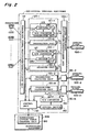
- Fig. 7 is a diagram showing the configuration of the conventional non-regenerative repeat type optical transmission system.
- optical terminal equipment 3000 and 6000 each have a plurality of subscribers 1000, 2000, convert subscriber signals from the subscribers 1000, 2000 into optical signals with E/O converters, and transmit the optical signals to the other optical terminal equipment 6000 and 3000 through two optical repeater equipment 4000 and 5000.
- the optical repeater equipment 4000 and 5000 amplify the optical signals with their amplifiers and transmit the optical signals to the two optical terminal equipment 6000 and 3000.
- the optical terminal equipment 6000 and 3000 convert the optical signals into electric signals with their O/E converters, and distribute to the subscribers 2000, 1000.
- the optical repeater equipment 4000 and 5000 each have optical fibers and light amplifiers connected thereto both corresponding to the number n of optical signals to be relayed by the two pieces of optical repeater equipment.
- the optical terminal equipment 3000 and 6000 to supervise the optical transmission system can obtain the correspondence relationship among the wavelengths ( ⁇ 1, ⁇ 2, ..., ⁇ n) of light rays to be relayed, the traveling directions of the rays, and the light amplifiers for the rays. For example, therefore it is known that an optical signal of wavelength ⁇ 1 travels in the upstream direction through optical fibers 7000-1, 7100-1 and 7200-1, and this optical signal is amplified by the light amplifiers 8000-1 and 8100-1.
- the optical repeater equipment Since normally the optical repeater equipment is an unmanned unit, it is required that information about the optical repeater equipment should be collected in manned optical terminal equipment, or in supervisory equipment installed at a place remote from the optical transmission system. For this purpose, one supervisory control signal is allocated to one transmission line, and this supervisory control signal conveys information about the pieces of optical repeater equipment along the line to the monitor station. For example, with the line of wavelength ⁇ 1, a supervisory control signal sv-1 conveys information about a light amplifier 8000-1 of optical repeater equipment 4000 and a light amplifier 8100-1 of optical repeater equipment 5000 to the monitor station.
- wavelength division multiplexing by which multiple wavelength signals are multiplexed along a single optical fiber, is becoming popularly employed in practical applications.
- WDM wavelength division multiplexing
- From a viewpoint of maintenance and management it is still necessary to detect the correspondence relationship of the wavelengths of optical signals, transmission directions, transmission lines, optical amplifiers, etc.
- a technique to efficiently concentrate information obtained at the optical repeater equipment into the supervisory equipment has not been established.
- optical repeater equipment having light amplifiers for amplifying multiplexed optical signal, to be placed between a pair of optical terminal equipment, at least one of said optical terminal equipment having a function to form a multiplexed optical signal by multiplexing a plurality of optical signals of mutually different wavelengths and at least one of said optical terminal equipment having a function to collect information for supervision of the transmission of said multiplexed optical signals, comprises first extracting means for extracting part of said multiplexed optical signal, first separating means for separating an extracted part of said multiplexed optical signal into component rays of said different wavelengths, first detecting means for detecting wavelengths of said separated component rays, generating means for generating a supervisory control signal, the supervisory control signal including a signal showing detected wavelengths of said separated component rays, and sending means for sending the supervisory control signal in the direction of the optical terminal equipment having said information collecting function.
- an optical transmission system has first optical terminal equipment for forming a multiplexed optical signal by multiplexing a plurality of component rays of mutually different wavelengths, supervisory equipment for collecting information for supervision of the transmission of said multiplexed optical signal, and optical repeater equipment provided with optical amplifiers for transmitting said multiplexed optical signal, wherein said optical repeater equipment comprises first extracting means for extracting part of said multiplexed optical signal, first separating means for separating an extracted part of said multiplexed optical signal into component rays of said different wavelengths, first detecting means for detecting wavelengths of separated component rays, generating means for generating a supervisory control signal, the supervisory control signal including a signal showing detected wavelengths of said separated component rays and sending means for sending the supervisory control signal in the direction of the optical terminal equipment having said information collecting function, and wherein the supervisory equipment comprises creating means for creating a supervisory control table for supervision of the transmission of said multiplexed optical signal.
- the optical repeater equipment analyses the state of the transmission of the multiplexed light for every wavelength, and collects results of analysis in the form of a supervisory control signal in one place. Under this arrangement, even when a transmission line is installed additionally, information on the supervised objects which increase with the addition of a transmission line can be collected using the current supervisory control signal, without adding on another supervisory control signal.
- the supervisory equipment which monitors the state of the transmission of the multiplexed optical signal, creates a supervisory control table for supervision of the optical transmission system on the basis of the received supervisory control signal. Consequently, even if a failure occurs in the transmission line, the maintenance person can easily and accurately make a decision about the replacement of parts and the switching of the lines.
- Fig. 1 is a diagram showing the configuration of the optical repeater equipment in the optical transmission system of the wavelength division multiplexing method according to an embodiment of the present invention.
- Fig. 2 is a diagram showing the configuration of the optical terminal equipment.
- Fig. 3 is a diagram showing the configuration of the optical transmission system using the optical terminal equipment in Fig. 2. For easier understanding, description will starts with the whole of the optical transmission system referring to Fig. 3 and then moves on to the optical repeater equipment and the optical terminal equipment referring to Figs. 1 and 2.
- the optical transmission system comprises optical terminal equipment 100, two optical repeater equipment 200, 300, optical terminal equipment 400, optical fibers 500-1 ⁇ m, 600-1 ⁇ m, and 700-1 ⁇ m, and supervisory equipment 800, in which m denotes the number of optical fibers.
- the main functions of the optical terminal equipment 100 are firstly to transmit and receive a subscriber signal to and from a subscriber 1000, secondly to convert a subscriber signal into an optical signal and transmits it to the optical repeater equipment 200, thirdly to convert an optical signal received from the optical repeater equipment 200 into an electric signal, and lastly to transmit and receive signals necessary to supervise the optical transmission system.
- the other optical terminal equipment 400 on the other side has the same functions.
- the main functions of the optical repeater equipment 200 are to amplify an optical signal from the optical terminal equipment 100 and transmit it to the optical repeater equipment 300, to amplify an optical signal from the optical repeater equipment 300 and transmit it to the optical terminal equipment 100, and to notify the state of the optical repeater equipment 200 to the optical terminal equipment 100.
- the other optical repeater equipment 300 has the same functions.
- the optical terminal equipment 100 comprises a subscriber signal multiplexer/demultiplexer unit 110, transmitter/receiver units 120-1 ⁇ m, optical wavelength multiplexer/demultiplexer units 130-1 ⁇ m, an O/E converter 150, and an optical switch 160.
- the subscriber signal multiplexer/demultiplexer unit 110 multiplexes the subscriber signals from the subscribers 1000 in time division and outputs the multiplexed signals to the transmitter/receiver units 120-1 ⁇ m, demultiplexes the multiplexed signals into subscriber signals and outputs to the subscribers 1000.
- the transmitter/receiver units 120-1 ⁇ m respectively include a plurality of transmitter units 121-1 ⁇ p and a plurality of receiver units 122-1 ⁇ q.
- p denotes the number of wavelengths to be multiplexed into the optical signal transmitted in the upstream direction (to the right of the paper)
- the q denotes the number of wavelengths to be multiplexed into the optical signal transmitted in the downstream direction (to the left of the paper) along the optical fiber 500-1.
- any number of light rays may be multiplexed on the other optical fibers 500-2 ⁇ m regardless of the numbers of light rays p and q multiplexed on the optical fiber 500-1.
- an encoder 123 codes the subscriber signal from the subscriber signal multiplexer/demultiplexer unit 110. For example, it codes pursuant to the SDH (Synchronous Digital Hierarchy: e.g., STM-1, STM-4, STM-16, or STM-64).
- the E/O converter 124 converts the coded signal into an optical signal ⁇ 1 using LD (Laser Diode).
- the optical signal ⁇ 1 is modulated by a local oscillator 125 to be given a transmission line optical fiber ID No. In short, the local oscillator 125 provides the transmission line ID No. for the optical signal ⁇ 1.
- the transmission line ID which is similar to the transmission line No. 1 ⁇ m, serves to specify which line the optical signal travels on.
- the encoder 123 in the transmitter/receiver unit 120-1 adds No. 1 of the transmission line 1 to the optical signal that travels along the line
- an encoder (not shown) in the transmitter/receiver unit 120-2 adds No. 2 of the transmission line 2 to the corresponding optical signal.
- the other transmitter units perform the same functions. Consequently, the optical signal ⁇ 1 is output to the optical wavelength multiplexer/demultiplexer unit 130-1.
- the optical wavelength multiplexer/demultiplexer unit 130-1 multiplexes optical signals ⁇ 1 to ⁇ p, in other words, multiplexes the optical signals in wavelength division, and transmits the multiplexed optical signal to the optical fiber 500-1.
- the optical wavelength multiplexer/demultiplexer unit 130-1 demultiplexes the optical signals ⁇ 1' to ⁇ q' received from the optical fiber 500-1, into component light rays of separate wavelengths, and outputs the separated light rays to the transmitter/receiver units 120-1 ⁇ m.
- the receiver unit 122-1 in the transmitter/receiver unit 120-1 demodulates the optical signal ⁇ 1 using the local oscillator 128, thus obtaining the transmission line ID.
- the O/E converter 127 converts the optical signal ⁇ 1' into the electric signal and the decoder 126 decodes the electric signal to output the decoded signal to the subscriber signal multiplexer/demultiplexer 110.
- the other receiver units 122-2 ⁇ q works similarly.
- the subscriber signal multiplexer/demultiplexer unit 110 demultiplexes the signals from the receiver units 122-1 ⁇ q in time division, and then outputs the time-division demultiplexed signals to the corresponding subscribers
- the supervisory control optical signal ⁇ sv In addition, in case of transmitting the supervisory control optical signal ⁇ sv upstream, one of the optical wavelength multiplexer/demultiplexer outputs to the optical fiber connected thereto, the supervisory control optical signal ⁇ sv received from the optical switch 160. In other word, the supervisory control optical signal ⁇ sv is transmitted to the opposite optical equipment 400 via one of the optical fiber 500-1 ⁇ m. Similarly, in case of transmitting the supervisory control optical signal ⁇ sv downstream, one of the optical wavelength multiplexer/demultiplexer outputs the supervisory control optical signal ⁇ sv received from the optical fiber connected thereto, to the optical switch 160.
- the functions of the control unit 140, O/E converter 150, and the optical switch 160 depends upon the direction of the transmitting the supervisory control optical signal ⁇ sv.
- the control unit 140 When the supervisory control optical signal ⁇ sv is forwarded upstream, the control unit 140 generates the supervisory control signal, the O/E converter 150 converts it into the supervisory control optical ⁇ sv, and the optical switch 160 outputs it to one of the optical wavelength multiplexer/demultiplexer unit 130-1.
- the supervisory control optical signal ⁇ sv is forwarded downstream, the optical switch 160 receives the supervisory control optical signal ⁇ sv from one of the optical wavelength multiplexer/demultiplexer unit, to output it to the O/E converter 150. Subsequently, the O/E converter 150 convert the supervisory control optical signal ⁇ sv into the supervisory control signal, thus outputting it to the control unit 140.
- the control unit 140 performs a specified signal conversion process, such as the U/B (Unipolar/Bipolar) conversion process on the supervisory control signal received from the O/E converter 150, and outputs the signal to a supervisory control table creating unit 810 in the supervisory equipment 800.
- the control unit 140 also obtains information necessary for supervision and control of the optical transmission system from each of the transmitter/receiver units 120-1 ⁇ m. For example, the control unit 140 receives information about BER (Bit Error Rate), switching of the transmission lines, etc., and sends the information to the supervisory equipment 800.
- BER Bit Error Rate
- the embodiment will focus on the states of optical transmission signal in the optical repeater equipment, which include, for example, the wavelengths of rays of light, the Nos. of the light amplifiers, the transmitting directions of optical signals, and the lines on which the optical signals travel.
- the supervisory control table creating unit 810 in the supervisory equipment 800 creates a supervisory control table, which will be described later, on the basis of a supervisory control signal received, and supplies the maintenance person with this supervisory control table. Description will be made in more detail later of the receiving function of the optical terminal equipment 100 and the function of the supervisory equipment 800.
- the optical repeater equipment 200 comprises repeater units 210-1 ⁇ m to relay downstream therefrom an optical signal sent from the optical terminal equipment 100, collects information by which to notify the states of transmission of the optical signal, and transmits a supervisory control signal to the adjacent optical terminal equipment or optical repeater equipment; a control unit 220 to generate a supervisory control signal from collected information; an E/O converter 230 to convert a generated supervisory control signal into a supervisory control light ray to convey the supervisory control signal; and an optical switch 240 to insert this supervisory control light ray into any of the transmission lines 1 to m.
- the optical coupler 211 in the repeater unit 210-1 extracts light transmitted along the optical fiber 500-1, while in case of transmitting it downstream, the optical coupler 219 extract light transmitted along the optical fiber 600-1,
- the optical couplers 211 and 219 are formed, for example, by a bulk type coupler, a fiber fusion type coupler, or an optical waveguide type coupler.
- the main object of the optical coupler 211 and 219 is to extract part of light, more specifically, partially extract light including all wavelength components. Therefore, any type of coupler will be available so long as it can extract light. However, considering loss of the optical signal by this light extraction, the ratio of the transmitted optical signal to the extracted optical signal should preferably be large.
- An optical demultiplexer 212 partially demultiplexes upstream multiplexed light of ⁇ 1 to ⁇ p, and similarly an optical demultiplexer 213 partially demultiplexes downstream multiplexed light of ⁇ 1' to ⁇ q'.
- a supervisory control ray ⁇ sv is also extracted.
- the optical demultiplexer 212 disperses the former multiplexed light of ⁇ 1 to ⁇ p and the supervisory control light ray ⁇ sv into rays of wavelengths ⁇ 1, ⁇ 2, ... ⁇ p, and ⁇ sv.
- the optical demultiplexer 213 disperses the latter multiplexed light of ⁇ 1' to ⁇ q' and the supervisory control light ray ⁇ sv into rays of wavelengths ⁇ 1', ⁇ 2',... ⁇ q' and ⁇ sv.
- Those optical demultiplexers 212, 213 are each formed by a prism, interference film filter, diffraction grating or the like.
- O/E converters 214-1 ⁇ p convert the dispersed component rays of wavelengths ⁇ 1 to ⁇ p respectively into electric signals.
- O/E converters 215-1 ⁇ q convert the dispersed component rays of wavelengths ⁇ 1' to ⁇ q' respectively into electric signals.
- O/E converters 214-sv and 215-sv convert the supervisory control rays ⁇ sv into supervisory control electric signals and output the supervisory control electric signals to a control unit 220.
- an O/E converter 214-1 outputs an electric signal, but if the received multiplexed light does not contain a ray of wavelength ⁇ 2, an O/E converter 214-2 does not output an electric signal, for which reason the presence of a ray of wavelength ⁇ 1 and the absence of a ray of wavelength ⁇ 2 are clarified.
- the optical signals ⁇ 1 ⁇ ⁇ p, and ⁇ 1' ⁇ q' experience demodulating by the respective local oscillators 216-1 ⁇ p, and 217-1 ⁇ q, thereby giving the transmission line ID to the control unit 220.
- the other repeater units 210-1 ⁇ m perform the same functions as in the repeater unit 210-1.
- the control unit 220 decides the wavelengths of the light rays contained in the received multiplexed light by deciding whether or not it receives electric signals from the O/E converters 214-1 ⁇ p and 215-1 ⁇ q. For example, if a signal is received from the O/E converter 214-1, the control unit 220 decides that a ray of wavelength ⁇ 1 has been received upstream, and if a signal is not received from the O/E converter 214-2, the control unit 220 decides that a ray of wavelength ⁇ 2 has not been received. The control unit 220 decides the transmission lines on which the rays of respective wavelengths have traveled, based upon the lines Nos.
- the control unit 220 decides that the ray of wavelength ⁇ 1 has traveled upstream through the line 1
- the control unit 220 decides that the ray of wavelength ⁇ p has traveled upstream through the line p.
- control unit 220 adds information received from the repeater units 210-1 ⁇ m, such as the wavelength of the ray transmitted, the line along which the ray has traveled, the light amplifier, and so on in specified time slots in supervisory control signals from the O/E converter 214-sv or 215-sv.
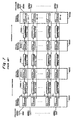
- Fig. 4 is a diagram showing the format of a supervisory control signal.
- the supervisory control signal consists of a frame bit (FRAME) for frame synchronization, an order wire (OW) block for a voice signal to exchange information between maintenance persons for maintenance and inspection, a data communication channel (DCC) block for information necessary for supervision of the optical transmission system, and a supervision information (SVINF) block for information about optical signals.
- the division for supervision information SVINF is divided into two sections corresponding to the two optical repeater equipment 200, 300 to convey information about the transmission of the optical signals. Each of those sections is divided into time slots as many as the number of wavelengths (p + q'). As shown in Fig.
- the control unit 220 inserts an optical signal wavelength, an optical signal direction, an optical amplifier No., and a transmission line ID No. to the corresponding time slots.
- the control unit 220 sets "1.533 ⁇ m" as the wavelength of the optical signal, "upstream” as the direction of the optical signal, "AMP No. 1" as the light amplifier No., "1" as the line ID No., and "line in service” as another item of this optical signal in the time slot for ⁇ 1.
- the control unit 220 outputs a supervisory control signal added with the above-mentioned items of information to the E/O converter 230.
- the E/O converter 230 generates a supervisory control optical signal from a supervisory control signal and supplies the supervisory control ray to an optical switch 240.
- the optical switch 240 switches over the output line of the supervisory control ray ⁇ sv to insert the supervisory control ray into one of the transmission lines 1 to m.
- the supervisory control ray ⁇ sv is inserted into one of the transmission lines 1 to m, which is selected by the optical switch 240 through the optical coupler 219 of one of the repeater units 210-1 ⁇ m.
- the ray is inserted through one of the optical couplers 219, while for downstream, the signal is inserted through one of the optical couplers 211.
- the optical terminal equipment 100 separates out a supervisory control ray ⁇ sv from the two pieces of optical repeater equipment 200, 300 by its optical wavelength multiplexer/demultiplexer unit 130-1 ⁇ m, and outputs the supervisory control ray to the optical switch 160.
- the control unit 140 selects a supervisory control ray ⁇ sv by using the optical switch 160 in response to a switching command from the supervisory equipment 800.
- the O/E converter 150 converts the selected supervisory control ray ⁇ sv into an electric signal, and outputs the electric signal, in other words, a supervisory control signal to the control unit 140.
- the control unit 140 extracts information about the respective optical signals from the time slots of supervisory control information in the received supervisory control signal, and outputs extracted supervisory control information to the supervisory equipment 800.
- the supervisory equipment 800 creates a supervisory control table for use in supervision of the whole optical transmission system from received supervisory control information.
- Fig. 5 is a diagram showing an example of connections of the optical transmission system.
- Fig. 6 is a supervisory control table created by the supervisory equipment.
- an optical signal (1.533 ⁇ m) is transmitted in the upstream direction along one optical fiber
- two optical signals (1.533 ⁇ m, 1.541 ⁇ m) are transmitted in the upstream direction along one optical fiber
- two other optical signals (1.549 ⁇ m, 1.557 ⁇ m) are also transmitted in the downstream direction along the same latter optical fiber.
- the optical fiber Nos., the light amplifier (AMP) Nos. and the line ID Nos. are assigned as shown in Fig. 6.
- the supervisory control table creating unit 810 in the supervisory equipment 800 collects information about the transmission of optical signals, that is, supervisory control information from the pieces of optical repeater equipment of the optical transmission system. From the collected supervisory control information, a supervisory control table necessary for supervision of the optical transmission system is created as shown in Fig. 6. This table makes it possible to accurately decide which fiber or which light amplifier should be checked when a failure occurs in the transmission of optical signals. For example, if a failure occurs in the transmission of an optical signal of a wavelength 1.541 ⁇ m, it is possible to make a quick and accurate decision that the optical fibers B1, B2 and B3 and the light amplifier No.2 and No. 5 should be checked.
- optical transmission system In the optical transmission system according to this embodiment of the invention, information about all optical repeater equipment is collected by using only one supervisory control ray ⁇ sv. Therefore, even in the installation of an additional line, it is possible to manage increased monitored objects due to the addition of a line, by altering only slightly the data format of the supervisory control signal in a supervisory control light ray without using any more supervisory control light ray. Consequently, it is possible to install additional lines at lower cost than in the conventional optical transmission system.
Landscapes
- Physics & Mathematics (AREA)
- Electromagnetism (AREA)
- Engineering & Computer Science (AREA)
- Computer Networks & Wireless Communication (AREA)
- Signal Processing (AREA)
- Optical Communication System (AREA)
- Monitoring And Testing Of Transmission In General (AREA)
Claims (12)
- Optische Verstärkereinrichtung (200) mit Lichtverstärkem (218) zum Verstärken von gemultiplexten optischen Signalen, zur Plazierung zwischen einem Paar von optischen Anschlusseinrichtungen (100, 400), wobei wenigstens eine der optischen Anschlusseinrichtungen (100, 400) die Funktion aufweist, ein gemultiplextes optisches Signal durch Multiplexen einer Mehrzahl von optischen Signalen von zueinander unterschiedlichen Wellenlängen zu bilden, und wenigstens eine der optischen Anschlusseinrichtungen (100) die Funktion aufweist, Information zur Überwachung der Übertragung der gemultiplexten optischen Signale zu sammeln, wobei die optische Verstärkereinrichtung (200) umfasst:erste Extraktionsmittel (219) zum Extrahieren eines Teils des gemultiplexten optischen Signals;erste Separationsmittel (213) zum Separieren eines extrahierten Teils des gemultiplexten optischen Signals in Komponentenstrahlen mit den verschiedenen Wellenlängen (λ 1' - λ q');erste Erfassungsmittel (215, 220) zum Erfassen von Wellenlängen (λ 1' - λ q') der separierten Komponentenstrahlen;Erzeugungsmittel (220, 230) zum Erzeugen eines Überwachungskontrollsignals, welches Überwachungskontrollsignal ein Signal enthält, das erfasste Wellenlängen (λ 1' - λ q') der separierten Komponentenstrahlen anzeigt; undSendemittel (240) zum Senden des Überwachungskontrollsignals in Richtung der optischen Anschlusseinrichtung (100), die die Informationssammelfunktion aufweist.
- Optische Verstärkereinrichtung (200) nach Anspruch 1, femer umfassend
zweite Extraktionsmittel (211) mit der gleichen Extraktionsfunktion wie in den ersten Extraktionsmitteln (219);
zweite Separationsmittel (212) mit der gleichen Separationsfunktion wie in den ersten Separationsmitteln (213); und
zweite Erfassungsmittel (214, 220) mit der gleichen Erfassungsfunktion wie in den ersten Erfassungsmitteln (215, 220),
wobei die ersten Extraktionsmittel (219), die ersten Separationsmittel (213), und die ersten Erfassungsmittel (215, 220) einen ersten Erfassungsmechanismus zum Erfassen von Wellenlängen (λ 1' - λ q') von Komponentenstrahlen des gemultiplexten optischen Signals bilden, das in Richtung der optischen Anschlusseinrichtung (100) mit den Informationssammelmitteln (800) übertragen wird, und wobei die zweiten Extraktionsmittel (211), die zweiten Separationsmittel (212), und die zweiten Erfassungsmittel (214, 220) einen zweiten Erfassungsmechanismus zum Erfassen von Wellenlängen (λ 1 - λ p) von Komponentenstrahlen des gemultiplexten Lichts bilden, das in die entgegengesetzte Richtung übertragen wird; und
wobei die Erzeugungsmittel (220, 230) ein Überwachungskontrollsignal erzeugen, welches Information über ein Korrespondenzverhältnis zwischen den Wellenlängen der Strahlen und den Richtungen enthält, in die die Strahlen mit den Wellenlängen übertragen werden. - Optische Verstärkereinrichtung (200) nach Anspruch 1 oder 2,
wobei den optischen Verstärkern (218) vorher Identifikationsnummern zugewiesen sind, und
wobei die Erzeugungsmittel (220, 230) ein Überwachungskontrollsignal erzeugen, das Information über ein Korrespondenzverhältnis zwischen den Identifikationsnummern der optischen Verstärker (218) und den Wellenlängen der Komponentenstrahlen des optischen Signals enthält, das durch die optischen Verstärker (218) übertragen wird. - Optische Verstärkereinrichtung (200) nach Anspruch 1, 2 oder 3, zum Anschluss an die zwei optischen Anschlusseinrichtungen (100, 400) mittels einer Mehrzahl von Übertragungsleitungen (1-m) zur Übertragung einer Mehrzahl von gemultiplexten optischen Signalen, ferner umfassend Lesemittel (216, 217, 220) zum Lesen von Übertragungsleitungsidentifikationsnummem, die der Mehrzahl von gemultiplexten optischen Signalen durch die optische Anschlusseinrichtung (100) gegeben sind, die die Funktion zum Bilden des gemultiplexten optischen Signals aufweist,
wobei die Erzeugungsmittel (220) ein Überwachungskontrollsignal erzeugen, das Information über ein Korrespondenzverhältnis zwischen den Wellenlängen des optischen Signals und den Übertragungsleitungsidentifikationsnummem enthält. - Optische Verstärkereinrichtung (200) nach einem der vorhergehenden Ansprüche, wobei die Erzeugungsmittel (220) ein Überwachungskontrollsignal bei der Verstärkereinrichtung (200) zu einem anderen Überwachungskontrollsignal hinzufügen, das von einer anderen optischen Einrichtung (300) empfangen wird, um ein anderes Überwachungskontrollsignal zu erzeugen.
- Optische Verstärkereinrichtung (200) nach einem der vorhergehenden Ansprüche, wobei die Sendemittel (240) das Überwachungskontrollsignal sendet unter Verwendung eines Überwachungskontrolllichts mit einer Wellenlänge (λ sv), die von den Wellenlängen des gemultiplexten optischen Signals verschieden ist.
- Optisches Übertragungssystem mit einer ersten optischen Anschlusseinrichtung (100) zum Bilden eines gemultiplexten optischen Signals durch Multiplexen einer Mehrzahl von Komponentenstrahlen von zueinander verschiedenen Wellenlängen, mit einer Überwachungseinrichtung (800) zum Sammeln von Information zur Überwachung der Übertragung des gemultiplexten optischen Signals, und mit einer optischen Verstärkereinrichtung (200), die mit optischen Verstärkern (218) versehen ist, um das gemultiplexte optische Signal zu übertragen,
wobei die optische Verstärkereinrichtung (200) umfasst:wobei die Überwachungseinrichtung Erschaffungsmittel zum Erschaffen einer Überwachungskontrolltabelle zur Überwachung der Übertragung des gemultiplexten optischen Signals enthält.erste Extraktionsmittel (219) zum Extrahieren eines Teils des gemultiplexten optischen Signals;erste Separationsmittel (213) zum Separieren eines extrahierten Teils des gemultiplexten optischen Signals in Komponentenstrahlen mit den verschiedenen Wellenlängen (λ 1' - λ q');erste Erfassungsmittel (215, 220) zum Erfassen von Wellenlängen (λ 1' - λ q') der separierten Komponentenstrahlen;Erzeugungsmittel (220, 230) zum Erzeugen eines Überwachungskontrollsignals, welches Überwachungskontrollsignal ein Signal enthält, das erfasste Wellenlängen (λ 1' - λ q') der separierten Komponentenstrahlen anzeigt; undSendemittel (240) zum Senden des Überwachungskontrollsignals in Richtung der optischen Anschlusseinrichtung (100), die die Informationssammelfunktion aufweist; und - Optisches Übertragungssystem nach Anspruch 7, ferner umfassend
eine zweite optische Anschlusseinrichtung (400) mit der gleichen Multiplexfunktion wie in der ersten optischen Anschlusseinrichtung (100),
wobei die optische Verstärkereinrichtung (200) ferner umfasst:wobei die ersten Extraktionsmittel (219), die ersten Separationsmittel (213), und die ersten Erfassungsmittel (215, 220) einen ersten Erfassungsmechanismus zur Erfassung von Wellenlängen (λ 1' - λ q') von Komponentenstrahlen des gemultiplexten optischen Signals bilden, das in Richtung der ersten optischen Anschlusseinrichtung (100) übertragen wird, und wobei die zweiten Extraktionsmittel (211), die zweiten Separationsmittel (212), und die zweiten Erfassungsmittel (214, 220) einen zweiten Erfassungsmechanismus zum Erfassen von Wellenlängen (λ 1 - λ p) von Komponentenstrahlen des gemultiplexten optischen Signals bilden, das in der entgegengesetzten Richtung übertragen wird,zweite Extraktionsmittel (211) mit der gleichen Extraktionsfunktion wie in den ersten Extraktionsmitteln (219);zweite Separationsmittel (212) mit der gleichen Separationsfunktion wie in den ersten Separationsmitteln (213); undzweite Erfassungsmittel (214, 220) mit der gleichen Erfassungsfunktion wie in den ersten Erfassungsmitteln (215, 220),
wobei die Erzeugungsmittel (220) ein Überwachungskontrollsignal erzeugen, das Information über ein Korrespondenzverhältnis zwischen den Wellenlängen des Signals und den Richtungen enthält, in welchen die Komponentenstrahlen mit den Wellenlängen übertragen werden. - Optisches Übertragungssystem nach Anspruch 8, wobei die Erschaffungsmittel (810) die Überwachungskontrolltabelle aus Information über das Korrespondenzverhältnis zwischen den Wellenlängen der Komponentenstrahlen und den Richtungen erschaffen, in denen die Komponentenstrahlen mit den Wellenlängen übertragen werden, welche in dem Überwachungskontrollsignal enthalten ist.
- Optisches Übertragungssystem nach Anspruch 7, 8 oder 9,
wobei den optischen Verstärkern (218) vorher Identifikationsnummern zugewiesen sind,
wobei die Erzeugungsmittel (220) ein Überwachungskontrollsignal aus einem Korrespondenzverhältnis zwischen den Identifikationsnummern der optischen Verstärker (218) und den Wellenlängen der Komponentenstrahlen erzeugen, die durch die optischen Verstärker (218) übertragen werden, und
wobei die Erschaffungsmittel (810) die Überwachungskontrolltabelle aus dem Korrespondenzverhältnis zwischen den Identifikationsnummern der optischen Verstärker (218) und den Wellenlängen der Komponentenstrahlen in dem Überwachungskontrollsignal erschaffen. - Optisches Übertragungssystem nach einem der Ansprüche 7 bis 10, ferner umfassend eine Mehrzahl von Übertragunsleitungen (1-m) zur Übertragung einer Mehrzahl von gemultiplexten optischen Signalen,
wobei die optische Anschlusseinrichtung (100) der Mehrzahl von gemultiplexten optischen Signalen Übertragungsleitungsidentifikationsnummern zuweist,
wobei die optische Verstärkereinrichtung (200) Lesemittel (216, 217, 220) zum Lesen der Übertragungsleitungsidentifikationsnummem umfasst,
wobei die Erzeugungsmittel (220) ein Überwachungskontrollsignal erzeugen, das Information über ein Korrespondenzverhältnis zwischen den Wellenlängen der Komponentenstrahlen und den Übertragunsleitungsidentifikationsnummern enthält, und
wobei die Erschaffungsmittel (810) die Überwachungskontrolltabelle aus dem Korrespondenzverhältnis zwischen den Wellenlängen der Komponentenstrahlen und den Übertragungsleitungsidentifikationsnummem erschaffen. - Optisches Übertragungssystem nach einem der Ansprüche 7 bis 11, wobei die optische Verstärkereinrichtung (200) ein Überwachungskontrollsignal überträgt, das von einer anderen optischen Einrichtung (100, 300) empfangen wurde, und zwar mittels eines nicht-regenerativen Verstärkungsverfahrens.
Applications Claiming Priority (6)
| Application Number | Priority Date | Filing Date | Title |
|---|---|---|---|
| JP26408896 | 1996-10-04 | ||
| JP26408896 | 1996-10-04 | ||
| JP264088/96 | 1996-10-04 | ||
| JP26925297 | 1997-09-16 | ||
| JP26925297A JPH10164026A (ja) | 1996-10-04 | 1997-09-16 | 光中継装置と光伝送システム |
| JP269252/97 | 1997-09-16 |
Publications (3)
| Publication Number | Publication Date |
|---|---|
| EP0835005A2 EP0835005A2 (de) | 1998-04-08 |
| EP0835005A3 EP0835005A3 (de) | 1999-03-17 |
| EP0835005B1 true EP0835005B1 (de) | 2004-12-22 |
Family
ID=26546345
Family Applications (1)
| Application Number | Title | Priority Date | Filing Date |
|---|---|---|---|
| EP97307839A Expired - Lifetime EP0835005B1 (de) | 1996-10-04 | 1997-10-03 | Optischer Verstärker und optisches Übertragungssystem |
Country Status (4)
| Country | Link |
|---|---|
| US (1) | US6018406A (de) |
| EP (1) | EP0835005B1 (de) |
| JP (1) | JPH10164026A (de) |
| CA (1) | CA2217263A1 (de) |
Families Citing this family (15)
| Publication number | Priority date | Publication date | Assignee | Title |
|---|---|---|---|---|
| JP3737896B2 (ja) * | 1997-11-28 | 2006-01-25 | 株式会社日立国際電気 | 中継システム |
| DE19828971A1 (de) * | 1998-06-29 | 2000-01-05 | Siemens Ag | Verfahren zur Überwachung der Signalqualität in optischen Netzen |
| DE19917751C2 (de) * | 1999-04-20 | 2001-05-31 | Nokia Networks Oy | Verfahren und Überwachungsvorrichtung zur Überwachung der Qualität der Datenübertragung über analoge Leitungen |
| US6587239B1 (en) * | 2000-02-23 | 2003-07-01 | Henry Hung | Optical fiber network having increased channel capacity |
| US7035292B1 (en) * | 2000-03-17 | 2006-04-25 | Applied Micro Circuits Corporation | Transposable frame synchronization structure |
| US6847657B1 (en) * | 2000-12-22 | 2005-01-25 | Applied Micro Circuits Corporation | System and method for programming synchronization criteria in a multidimensional digital frame structure |
| US6931006B1 (en) * | 2000-12-22 | 2005-08-16 | Applied Micro Circuits Corporation | System and method for selectively broadcasting a multidimensional digital frame structure |
| JP3813063B2 (ja) * | 2001-02-01 | 2006-08-23 | 富士通株式会社 | 通信システム及び波長分割多重装置 |
| JP3946468B2 (ja) * | 2001-07-11 | 2007-07-18 | 三菱電機株式会社 | 光中継システムおよび光増幅中継器制御方法 |
| AU2002341893A1 (en) * | 2001-10-01 | 2003-04-14 | Nortel Networks Limited | Fault signalling in optical communications networks |
| US7146101B2 (en) * | 2001-11-08 | 2006-12-05 | Altera Corporation | Optical media management channel |
| US6853763B1 (en) | 2002-03-27 | 2005-02-08 | Nortel Networks Limited | Photonic switching including photonic pass-through and add/drop capabilities |
| JP4516739B2 (ja) * | 2003-12-05 | 2010-08-04 | 富士通株式会社 | 光伝送装置および光伝送システム |
| US9092380B1 (en) * | 2007-10-11 | 2015-07-28 | Norberto Menendez | System and method of communications with supervised interaction |
| JP2009232193A (ja) * | 2008-03-24 | 2009-10-08 | Nec Corp | 通信システムおよび監視/制御方法および中継装置およびプログラム |
Family Cites Families (7)
| Publication number | Priority date | Publication date | Assignee | Title |
|---|---|---|---|---|
| JP3137632B2 (ja) * | 1989-08-31 | 2001-02-26 | 富士通株式会社 | 光ファイバ増幅器を備えた光通信方式 |
| JPH05199184A (ja) * | 1992-01-20 | 1993-08-06 | Fujitsu Ltd | 光増幅中継器 |
| US5500756A (en) * | 1992-02-28 | 1996-03-19 | Hitachi, Ltd. | Optical fiber transmission system and supervision method of the same |
| US5555477A (en) * | 1992-04-08 | 1996-09-10 | Hitachi, Ltd. | Optical transmission system constructing method and system |
| JP2734969B2 (ja) * | 1993-12-29 | 1998-04-02 | 日本電気株式会社 | 波長多重伝送用光ファイバ増幅器 |
| JP3373332B2 (ja) * | 1995-05-26 | 2003-02-04 | Kddi株式会社 | プリエンファシス方式光波長多重通信方法および装置 |
| JPH09185091A (ja) * | 1995-12-28 | 1997-07-15 | Nec Corp | 波長多重光伝送装置 |
-
1997
- 1997-09-16 JP JP26925297A patent/JPH10164026A/ja active Pending
- 1997-10-02 US US08/942,532 patent/US6018406A/en not_active Expired - Lifetime
- 1997-10-03 EP EP97307839A patent/EP0835005B1/de not_active Expired - Lifetime
- 1997-10-03 CA CA002217263A patent/CA2217263A1/en not_active Abandoned
Also Published As
| Publication number | Publication date |
|---|---|
| US6018406A (en) | 2000-01-25 |
| EP0835005A3 (de) | 1999-03-17 |
| EP0835005A2 (de) | 1998-04-08 |
| JPH10164026A (ja) | 1998-06-19 |
| CA2217263A1 (en) | 1998-04-04 |
Similar Documents
| Publication | Publication Date | Title |
|---|---|---|
| EP0835005B1 (de) | Optischer Verstärker und optisches Übertragungssystem | |
| JP3102379B2 (ja) | 波長多重光伝送システム用監視制御方式 | |
| US5875046A (en) | Optical repeater and optical transmitter | |
| US6266169B1 (en) | Optical transmission equipment which transmits an amplified optical data signal and an optical surveillance signal | |
| US7286758B2 (en) | Method for switching transmission route, and optical transmission device | |
| EP1004175B1 (de) | Verfahren und vorrichtung für die datenübertragung über einen lichtwellenleiter | |
| EP1056235A2 (de) | Optisches Ringsystem | |
| US7548693B2 (en) | Relay transmission apparatus | |
| US6735392B1 (en) | System and method for transmitting and restoring an optical signal | |
| KR100594095B1 (ko) | 양방향 파장분할 다중방식 애드/드롭 자기치유 허브형환형망 | |
| US6005699A (en) | Optical wavelength multiplexing system | |
| US5493432A (en) | Optical communication system | |
| US7609970B2 (en) | Add/drop node for an optical communications network | |
| JP2007514380A (ja) | 光トラフィックを通信するための方法及びシステム | |
| CN101562493A (zh) | 波分环视频光端机 | |
| US7853146B2 (en) | Optical transmission apparatus | |
| WO1999018679A1 (en) | An optical network with protection path for failure recovery | |
| JP2000286824A (ja) | 波長分割多重通信システム | |
| JPH04294647A (ja) | 光増幅中継伝送装置 | |
| JPS6130782B2 (de) | ||
| JPH11313032A (ja) | D−wdmシステムにおける障害切り分け装置 | |
| JPH07312765A (ja) | 光波長多重伝送装置 | |
| KR20000014563A (ko) | 파장 다중화 전송시스템에서 파장정보 전송방법 | |
| WO2001013561A1 (en) | Optical bi-directional line switched ring for wdm transmission systems | |
| JP2002051012A (ja) | 波長多重光伝送システム |
Legal Events
| Date | Code | Title | Description |
|---|---|---|---|
| PUAI | Public reference made under article 153(3) epc to a published international application that has entered the european phase |
Free format text: ORIGINAL CODE: 0009012 |
|
| AK | Designated contracting states |
Kind code of ref document: A2 Designated state(s): FR GB IT |
|
| AX | Request for extension of the european patent |
Free format text: AL;LT;LV;RO;SI |
|
| PUAL | Search report despatched |
Free format text: ORIGINAL CODE: 0009013 |
|
| AK | Designated contracting states |
Kind code of ref document: A3 Designated state(s): AT BE CH DE DK ES FI FR GB GR IE IT LI LU MC NL PT SE |
|
| AX | Request for extension of the european patent |
Free format text: AL;LT;LV;RO;SI |
|
| 17P | Request for examination filed |
Effective date: 19990415 |
|
| AKX | Designation fees paid |
Free format text: FR GB IT |
|
| REG | Reference to a national code |
Ref country code: DE Ref legal event code: 8566 |
|
| 17Q | First examination report despatched |
Effective date: 20030325 |
|
| GRAP | Despatch of communication of intention to grant a patent |
Free format text: ORIGINAL CODE: EPIDOSNIGR1 |
|
| RIC1 | Information provided on ipc code assigned before grant |
Ipc: 7H 04B 10/17 A |
|
| GRAS | Grant fee paid |
Free format text: ORIGINAL CODE: EPIDOSNIGR3 |
|
| GRAA | (expected) grant |
Free format text: ORIGINAL CODE: 0009210 |
|
| AK | Designated contracting states |
Kind code of ref document: B1 Designated state(s): FR GB IT |
|
| PG25 | Lapsed in a contracting state [announced via postgrant information from national office to epo] |
Ref country code: IT Free format text: LAPSE BECAUSE OF FAILURE TO SUBMIT A TRANSLATION OF THE DESCRIPTION OR TO PAY THE FEE WITHIN THE PRESCRIBED TIME-LIMIT;WARNING: LAPSES OF ITALIAN PATENTS WITH EFFECTIVE DATE BEFORE 2007 MAY HAVE OCCURRED AT ANY TIME BEFORE 2007. THE CORRECT EFFECTIVE DATE MAY BE DIFFERENT FROM THE ONE RECORDED. Effective date: 20041222 Ref country code: FR Free format text: LAPSE BECAUSE OF FAILURE TO SUBMIT A TRANSLATION OF THE DESCRIPTION OR TO PAY THE FEE WITHIN THE PRESCRIBED TIME-LIMIT Effective date: 20041222 |
|
| REG | Reference to a national code |
Ref country code: GB Ref legal event code: FG4D |
|
| PLBE | No opposition filed within time limit |
Free format text: ORIGINAL CODE: 0009261 |
|
| STAA | Information on the status of an ep patent application or granted ep patent |
Free format text: STATUS: NO OPPOSITION FILED WITHIN TIME LIMIT |
|
| 26N | No opposition filed |
Effective date: 20050923 |
|
| EN | Fr: translation not filed | ||
| REG | Reference to a national code |
Ref country code: GB Ref legal event code: 732E Free format text: REGISTERED BETWEEN 20090716 AND 20090722 |
|
| PGFP | Annual fee paid to national office [announced via postgrant information from national office to epo] |
Ref country code: GB Payment date: 20160926 Year of fee payment: 20 |
|
| REG | Reference to a national code |
Ref country code: GB Ref legal event code: PE20 Expiry date: 20171002 |
|
| PG25 | Lapsed in a contracting state [announced via postgrant information from national office to epo] |
Ref country code: GB Free format text: LAPSE BECAUSE OF EXPIRATION OF PROTECTION Effective date: 20171002 |