EP0834603A1 - Verfahren zum richten eines stahlbandes in einer galvanisierungslinie - Google Patents
Verfahren zum richten eines stahlbandes in einer galvanisierungslinie Download PDFInfo
- Publication number
- EP0834603A1 EP0834603A1 EP97908502A EP97908502A EP0834603A1 EP 0834603 A1 EP0834603 A1 EP 0834603A1 EP 97908502 A EP97908502 A EP 97908502A EP 97908502 A EP97908502 A EP 97908502A EP 0834603 A1 EP0834603 A1 EP 0834603A1
- Authority
- EP
- European Patent Office
- Prior art keywords
- steel strip
- roll
- current
- carrying
- backup
- Prior art date
- Legal status (The legal status is an assumption and is not a legal conclusion. Google has not performed a legal analysis and makes no representation as to the accuracy of the status listed.)
- Granted
Links
Images

Classifications
-
- C—CHEMISTRY; METALLURGY
- C25—ELECTROLYTIC OR ELECTROPHORETIC PROCESSES; APPARATUS THEREFOR
- C25D—PROCESSES FOR THE ELECTROLYTIC OR ELECTROPHORETIC PRODUCTION OF COATINGS; ELECTROFORMING; APPARATUS THEREFOR
- C25D7/00—Electroplating characterised by the article coated
- C25D7/06—Wires; Strips; Foils
- C25D7/0614—Strips or foils
- C25D7/0621—In horizontal cells
Definitions
- the present invention relates to a method of producing an electroplated steel sheet, and particularly to a method of correcting warpage of a steel strip in an electroplating line.
- each of the current-carrying rolls comprises an iron roll
- each of the backup rolls comprises a rubber roll.
- the surfaces of the rubber rolls are concavely deformed due to a difference in hardness between iron and rubber, thereby bending the steel strip along deformation.
- an iron roll is provided on the upper side
- a rubber roll is provided on the lower side
- the steel strip is bent concavely upward, and pulled by tensile force to produce warpage of the steel strip in the width direction thereof. Warpage of the steel strip causes problems of nonuniformity in plating, etc.
- Japanese Patent Unexamined Publication No. 3-126890 discloses a technique in which widthwise warpage deformation of a steel strip is constantly detected in a plating bath, and backup rolls are shifted in the pass direction of the steel strip while maintaining the predetermined pressure on current-carrying rolls on the basis of the detection signal, to correct widthwise warpage of the steel strip.
- the method comprising shifting the backup rolls according to the warpage amount of the steel strip has a problem in that it is very difficult to shift the backup rolls in the direction of movement of the steel strip while maintaining the predetermined pressure on the current-carrying rolls.
- the backup rolls are shifted under supply of electricity, a spark occurred on a gap which is generated between the current-carrying rolls and the steel strip, thereby causing the problem of damaging the surfaces of the steel strip and the current-carrying rolls.
- This technique also has a problem in that when the steel strip significantly warps, the shift amount of the backup rolls is increased, and thus the pass line of the steel strip significantly changes, thereby causing a difference between the amounts of the deposits on the face and back of the steel strip.
- An object of the present invention is to provide a method of correcting warpage of a steel strip in an electroplating line in which the above-described drawbacks are improved.
- the present invention has been developed for solving the above problems, and provides a method of correcting warpage of a steel strip in a horizontal electroplating line comprising current-carrying rolls and backup rolls with a steel strip held therebetween, the method comprising forming at least one of the backup rolls so that the backup roll is smaller than the opposite current-carrying roll, and arranging the rolls so that the backup roll is shifted (simply referred to as "offset" hereinafter) relatively to the opposite current-carrying roll in the movement direction of the steel strip.
- the offset amount is preferably within the range of 5 to 35 mm.
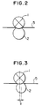
- the criterion of offset is in a state where the line connecting the center of the backup roll diameter and the center of the opposite current-carrying roll diameter is perpendicular to the pass line of the steel strip, as shown in Fig. 2. In this state, the offset amount is considered as zero.
- An operation of the present invention is as follows. If a backup roll is offset relatively to an opposite current-carrying roll in the movement direction of the steel strip, the steel strip passed through the current-carrying roll is wound around the backup roll and thus rebent in the direction reverse to bending by the current-carrying roll, thereby relieving residual bending stress. If the offset amount is increased, the effect of correcting warpage is increased, but the steel strip is moved upward from the pass line in the portions of contact with the current-carrying roll, and thus the position of the steel strip is changed. Therefore, the backup roll diameter is made smaller than the current-carrying roll diameter to improve the warpage correcting effect and keep the offset amount in a low level.
- each of the backup rolls is formed to be smaller than the opposite current-carrying roll, and is offset relatively to the current-carrying roll by an amount within the range of 5 to 35 mm in the movement direction of the steel strip, it is possible to desirably correct warpage of the steel strip.
- Offset may be achieved by moving the backup roll forward relatively to the opposite current-carrying roll in the movement direction of the steel strip. This may also be achieved by moving the backup roll forward, moving the opposite current-carrying roll backward or by both methods.
- the offset amount can be properly determined according to the conditions such as the thickness, width, mechanical property and yield stress of the steel strip, arrangement and the sizes of the current-carrying rolls and the backup rolls, a difference in hardness therebetween, etc., as described below.
- the backup roll With a small offset amount, the backup roll has the low function to rebend the steel strip and a small effect.
- the offset amount is preferably within the range of 5 mm to 35 mm, which makes it possible to suppress a change in the pass line of the steel strip.
- the offset amounts of a plurality of backup rolls may be set to different values.
- the diameter of a backup roll is preferably 0.50 to 0.97D relative to the diameter D of an opposite current-carrying roll. If the diameter of the backup roll exceeds 0.97D, the offset amount must be increased, and the diameter reduction is meaningless. If the diameter of the backup roll is less than 0.50D, the offset backup roll undesirably has only a little force to hold the steel strip. Although the diameter of the backup roll depends upon other conditions, the diameter is preferably about 0.80D.
- the inventors determined the relations of the offset amount d (mm) required for minimizing ( ⁇ 0) warpage of the steel strip to the thickness t (mm) of the steel strip, yield stress ⁇ e (kgf/mm 2 ), tensile force ⁇ T (kgf/mm 2 ), the diameter L 1 of the current-carrying roll, and the diameter L 2 of the opposite backup roll.
- the offset amount d is represented by the following relation expression.
- a is a value determined by the hardness and pressure of the current-carrying roll and the opposite backup roll, and can be determined by measuring the nip width between both rolls.
- the optimum offset amount d is determined so that the warpage of the steel strip is zero according to equation (1), and the backup roll or the current-carrying roll has previously been offset by an amount d so that warpage of the steel strip can be corrected without occurrence of spark flaws due to inferior contact between the current-carrying roll and the steel strip.
- Warpage of the steel strip is due to the fact that the surface of the rubber roll is concavely deformed due to a difference in hardness between the current-carrying roll and the opposite backup roll, and thus the steel strip is bent concavely upward.
- the amount of warpage can be controlled by controlling the amount of bending of the steel strip, i.e., the working radius of curvature. Therefore, in order to make the warpage of the steel strip zero after passing through the current-carrying roll, the working radius of curvature ⁇ 1 due to a difference in hardness between the current-carrying roll and the opposite backup roll may be equal to the working radius of curvature ⁇ 2 due to offset of the backup roll.
- the offset amount required for making warpage of the steel strip zero is computed according to equation (1), and the steel strip is previously offset before working, it is possible to stably pass the steel strip and correct warpage thereof.
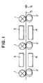
- FIG. 1 A schematic drawing of a plating apparatus.
- FIG. 2 A drawing illustrating the relation between a conventional current-carrying roll and backup roll.
- FIG. 3 A drawing illustrating the relation between a current-carrying roll and a backup roll of the present invention.
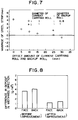
- FIG. 4 A graph showing the relation between an offset amount required for making warpage zero and the sheet thickness.
- FIG. 5 A graph showing the relation between an offset amount required for making warpage zero and yield stress.
- FIG. 6 A graph showing the relation between an offset amount required for making warpage zero and the diameter ratio of a backup roll to a current-carrying roll.
- FIG. 7 A graph showing the results of measurement of warpage of a steel strip in a plating apparatus.
- FIG. 8 A graph showing deposit distributions in the width direction before and after improvement.
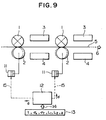
- FIG. 9 A schematic drawing of a warpage correcting apparatus in accordance with an embodiment of the present invention.
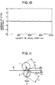
- FIG. 10 A graph showing the results of measurement of warpage of a steel strip in the lengthwise direction thereof as an example of the effect of the present invention.
- FIG. 11 A drawing showing the principle of correction of warpage of a steel strip by offset.
- setting the offset amount between a current-carrying roll and an opposite backup roll within the range of 5 to 35 mm makes it possible to maintain the pressure between the current- carrying roll and the backup roll at a constant value, and prevent the occurrence of spark between the current- carrying roll and a steel strip. Also, by setting the offset amount to 35 mm or less, the vertical variation of the pass line of the steel strip can be suppressed to 2 mm or less, and no difference occurs between the deposits on the face and back of the steel strip. Also, by setting the offset amount between the current-carrying roll and the backup roll to 5 mm or more, and the diameter of the backup roll to be smaller than that of the current-carrying rolls, it is possible to improve the effect of correcting warpage of the steel strip.
- Fig. 1 is a schematic drawing of a horizontal plating apparatus in accordance with an embodiment of the invention.
- a steel strip 5 is moved in the movement direction 6.
- Current-carrying rolls 1 and backup rolls 2 are arranged to vertically hold the steel strip 5 therebetween, and upper electrodes 3 and lower electrodes 4 are disposed between the respective current-carrying rolls 1 so that the steel strip 5 is plated by flowing a plating solution between the electrodes 3 and 4, and passing a current.
- Fig. 2 is a drawing showing the arrangement of a conventional current-carrying roll 1 and backup roll 2.
- the current-carrying roll 1 and the backup roll 2 are disposed at the same position in the movement direction of the steel strip 5 to vertically hold the steel strip therebetween. Since the conductor roll 1 comprises an iron roll, while the backup roll 2 comprises a rubber roll, the backup roll 2 is depressed due to a difference in hardness, and the steel strip 5 is passed between the rolls, thereby bending the steel strip 5. The residual stress produced at this time is pulled by tensile force to cause warpage in the steel strip in the width direction thereof.
- Fig. 3 is a drawing showing an embodiment of the present invention.
- This drawing shows a case where a backup roll 2 is offset relatively to a current-carrying roll 1 by an amount d in the movement direction of a steel strip 5.
- the same offset effect can also be achieved by moving the current-carrying roll 1 in the direction reverse to the movement direction of the steel strip, while the backup roll 2 is fixed.
- the steel strip 5 is bent due to a difference in hardness between the current-carrying roll 1 and the backup roll 2, the steel strip 5 contacts the backup roll 2 even after being passed through the current-carrying roll 1, and pulled by tensile force, thereby winding the steel strip 5 on the backup roll 2.
- the steel strip 5 is bent by the backup roll 2 in the direction reverse to bending by the current-carrying roll 1, thereby relieving the residual stress produced by the current-carrying roll 1.
- the offset amount d is increased, the amount of winding of the steel strip 5 on the backup roll 2 is increased, and the radius of curvature approaches the diameter of the backup roll 2, thereby increasing the warpage correcting effect.
- the offset amount is increased, since the contact portion between the backup roll 2 and the current-carrying roll 1 is moved upward from the pass line, the vertical position of the steel strip 5 is also moves upward, and thus a difference occurs between the thicknesses of the deposits on the face and back of the steel strip. Therefore, the diameter of the backup roll 2 is made smaller than that of the current-carrying roll 1 to improve the warpage correcting effect, and the offset amount is minimized to suppress a rise of the pass line of the steel strip 5 to 2 mm or less.
- the offset amount is determined according to various factors.
- Figs. 4, 5 and 6 show examples of the relations between the offset amount required for making warpage zero to the sheet thickness, yield stress and the backup roll diameter/current-carrying roll diameter, which were examined by changing these factors while fixing other factors, in comparison with general conditions in which the sheet thickness was 1.0 mm, yield stress was 16 kgf/mm 2 , the current-carrying diameter was 375 mm, the nip width (a) between the current-carrying roll and the backup roll was 37.5 mm, and the tensile force of a sheet was 3 kgf/mm 2 .
- o marks show the case where the diameter of the backup roll is 0.8D relative to the diameter D of the current-carrying roll.
- ⁇ marks show the case where the diameter of the backup roll is equal to the diameter of the current-carrying roll.
- Fig. 7 indicates that, in this example, warpage of the steel strip can be zero by setting the offset amount to 24.3 m.
- the relation shown in Fig. 7 can previously be determined according to conditions of the steel strip, and the offset amount is properly previously set so that the warpage of the steel strip can be minimized.
- Fig. 9 is a drawing showing an embodiment of the present invention.
- Reference numerals 1 to 6 denote the same as those shown in Fig. 1.
- Data 13 such as the thickness t of the steel strip, yield stress ⁇ e , tensile force ⁇ T , the current-carrying roll diameter L 1 , the backup roll diameter L 2 , and the nip pressure a between both rolls are input 14 to an arithmetic device 12 to compute the optimum offset d by the arithmetic device 12 according to the above equation (1), and the output 15 is output to shifters 11 for shifting the backup rolls 2.
- the shifters 11 receive the output 15 when a joint material is passed before the steel strip is passed to shift the backup rolls by the offset amount d , and then the steel strip is passed and plated. Therefore, the steel strip can be passed while maintaining the pressure on the steel strip, and there is thus no possibility that spark flaws occur due to the inferior contact between the steel strip and the current-carrying rolls. Since the backup rolls have previously been shifted before the steel strip is passed, warpage of the steel strip can be corrected over the whole length thereof.
- Fig. 10 is a graph showing the results of measurement of lengthwise warpage of the steel strip in accordance with the method of the present invention.
- the warpage of the steel strip could be substantially zero over the whole length thereof, as shown in Fig. 10.
- occurrence of spark flaws due to the inferior contact between the rolls was not observed.
- the diameter of s backup roll smaller than that of an opposite current-carrying roll, it is possible to improve the effect of correcting warpage of the steel strip, decrease the offset amount between the current-carrying roll and the backup roll, decrease the vertical variation of the pass line of the steel strip, and decrease differences between the deposits on the face and back of the steel strip and in the widthwise direction thereof.
- the offset amount required for making zero warpage of the steel strip is computed from the thickness of the steel strip, yield stress, tensile force, the current-carrying roll diameter, the backup roll diameter, and the nip width between both rolls, and either of the current-carrying roll or the backup roll have previously been shifted before the steel strip is passed and plated so that warpage of the steel strip can be corrected without the occurrence of spark flaws due to the inferior contact between the steel strip and the current-carrying roll. Also, since the roll is previously offset, there is the effect of correcting warpage of the steel strip over the whole length thereof.
Landscapes
- Chemical & Material Sciences (AREA)
- Engineering & Computer Science (AREA)
- Chemical Kinetics & Catalysis (AREA)
- Electrochemistry (AREA)
- Materials Engineering (AREA)
- Metallurgy (AREA)
- Organic Chemistry (AREA)
- Electroplating Methods And Accessories (AREA)
- Straightening Metal Sheet-Like Bodies (AREA)
Applications Claiming Priority (7)
| Application Number | Priority Date | Filing Date | Title |
|---|---|---|---|
| JP7773396 | 1996-03-29 | ||
| JP77733/96 | 1996-03-29 | ||
| JP7773396 | 1996-03-29 | ||
| JP15560296 | 1996-06-17 | ||
| JP15560296 | 1996-06-17 | ||
| JP155602/96 | 1996-06-17 | ||
| PCT/JP1997/000988 WO1997037063A1 (en) | 1996-03-29 | 1997-03-25 | Method of straightening warp of steel strip in electroplating line |
Publications (3)
| Publication Number | Publication Date |
|---|---|
| EP0834603A1 true EP0834603A1 (de) | 1998-04-08 |
| EP0834603A4 EP0834603A4 (de) | 1998-12-09 |
| EP0834603B1 EP0834603B1 (de) | 2001-08-08 |
Family
ID=26418803
Family Applications (1)
| Application Number | Title | Priority Date | Filing Date |
|---|---|---|---|
| EP97908502A Expired - Lifetime EP0834603B1 (de) | 1996-03-29 | 1997-03-25 | Verfahren zum richten eines stahlbandes in einer galvanisierungslinie |
Country Status (6)
| Country | Link |
|---|---|
| US (1) | US6019884A (de) |
| EP (1) | EP0834603B1 (de) |
| KR (1) | KR100293117B1 (de) |
| CN (1) | CN1094526C (de) |
| DE (1) | DE69706016T2 (de) |
| WO (1) | WO1997037063A1 (de) |
Family Cites Families (5)
| Publication number | Priority date | Publication date | Assignee | Title |
|---|---|---|---|---|
| JPS59153379A (ja) * | 1983-02-21 | 1984-09-01 | Matsushita Electric Ind Co Ltd | デイジタル輪郭補償回路 |
| JPS59153379U (ja) * | 1983-04-01 | 1984-10-15 | 住友金属工業株式会社 | 電気メツキ用通電ロ−ル装置 |
| JPH03126890A (ja) * | 1989-10-12 | 1991-05-30 | Nisshin Steel Co Ltd | 電気めっき方法 |
| JPH03236495A (ja) * | 1990-02-14 | 1991-10-22 | Kawasaki Steel Corp | 横型電気めっき装置 |
| JPH05125588A (ja) * | 1991-10-09 | 1993-05-21 | Taisho Kogyo Kk | 給電ロール装置 |
-
1997
- 1997-03-25 US US08/952,283 patent/US6019884A/en not_active Expired - Fee Related
- 1997-03-25 EP EP97908502A patent/EP0834603B1/de not_active Expired - Lifetime
- 1997-03-25 WO PCT/JP1997/000988 patent/WO1997037063A1/ja not_active Ceased
- 1997-03-25 DE DE69706016T patent/DE69706016T2/de not_active Expired - Fee Related
- 1997-03-25 CN CN97190595A patent/CN1094526C/zh not_active Expired - Fee Related
- 1997-03-25 KR KR1019970708680A patent/KR100293117B1/ko not_active Expired - Fee Related
Non-Patent Citations (2)
| Title |
|---|
| No further relevant documents disclosed * |
| See also references of WO9737063A1 * |
Also Published As
| Publication number | Publication date |
|---|---|
| KR19990022201A (ko) | 1999-03-25 |
| DE69706016T2 (de) | 2002-05-29 |
| CN1094526C (zh) | 2002-11-20 |
| KR100293117B1 (ko) | 2002-05-15 |
| EP0834603A4 (de) | 1998-12-09 |
| EP0834603B1 (de) | 2001-08-08 |
| WO1997037063A1 (en) | 1997-10-09 |
| CN1194673A (zh) | 1998-09-30 |
| US6019884A (en) | 2000-02-01 |
| DE69706016D1 (de) | 2001-09-13 |
Similar Documents
| Publication | Publication Date | Title |
|---|---|---|
| EP0834603B1 (de) | Verfahren zum richten eines stahlbandes in einer galvanisierungslinie | |
| Masui et al. | Warp control in strip processing plant | |
| EP0543014B1 (de) | Sechs-walzen-walzwerk | |
| JPH0521653B2 (de) | ||
| JP3421798B2 (ja) | 電気めっきラインにおける鋼帯の反り矯正方法 | |
| US5322614A (en) | Device for electrolytic deposition of metals on one or both sides of strips | |
| US5724845A (en) | Bowing correction apparatus for temper rolling mill | |
| JP2833508B2 (ja) | 電気めっきにおける通電ロールのバックアップロール | |
| JP2810333B2 (ja) | 電気メッキライン用テンションレベラーおよび帯板矯正方法 | |
| US4501647A (en) | Method of electroplating | |
| JPH03126890A (ja) | 電気めっき方法 | |
| JPS6365759B2 (de) | ||
| JPH07117364B2 (ja) | 冷延鋼板の形状測定方法 | |
| JPH0116319B2 (de) | ||
| JPH06306695A (ja) | 金属ストリップの連続電気めっき設備ならびに幅方向めっき付着量制御方法 | |
| JPH06306693A (ja) | 金属ストリップの幅方向めっき付着量制御用めっき電極ならびにめっき付着量制御方法 | |
| JPH0813194A (ja) | ストリップの電気めっき方法および装置 | |
| JPH05339787A (ja) | 連続電気めっき方法 | |
| JP2776937B2 (ja) | 鋼帯の蛇行防止方法 | |
| JP2003055791A (ja) | 鋼帯の電気鍍金方法 | |
| JP2719216B2 (ja) | 板圧延のエッジドロップ制御方法 | |
| CA1331744C (en) | Apparatus for plating metal strip in electrolytic cell | |
| JP2023150165A (ja) | 金属帯の電気鍍金装置、金属帯の電気鍍金方法、及び鍍金鋼板の製造方法 | |
| JPH10305315A (ja) | 残留応力の低減された金属帯板の製造方法 | |
| JPH07108307A (ja) | 圧延機におけるミル剛性の調整方法 |
Legal Events
| Date | Code | Title | Description |
|---|---|---|---|
| PUAI | Public reference made under article 153(3) epc to a published international application that has entered the european phase |
Free format text: ORIGINAL CODE: 0009012 |
|
| 17P | Request for examination filed |
Effective date: 19971127 |
|
| AK | Designated contracting states |
Kind code of ref document: A1 Designated state(s): DE FR GB |
|
| A4 | Supplementary search report drawn up and despatched |
Effective date: 19981022 |
|
| AK | Designated contracting states |
Kind code of ref document: A4 Designated state(s): DE FR GB |
|
| GRAG | Despatch of communication of intention to grant |
Free format text: ORIGINAL CODE: EPIDOS AGRA |
|
| 17Q | First examination report despatched |
Effective date: 20000920 |
|
| GRAG | Despatch of communication of intention to grant |
Free format text: ORIGINAL CODE: EPIDOS AGRA |
|
| GRAH | Despatch of communication of intention to grant a patent |
Free format text: ORIGINAL CODE: EPIDOS IGRA |
|
| GRAH | Despatch of communication of intention to grant a patent |
Free format text: ORIGINAL CODE: EPIDOS IGRA |
|
| GRAA | (expected) grant |
Free format text: ORIGINAL CODE: 0009210 |
|
| AK | Designated contracting states |
Kind code of ref document: B1 Designated state(s): DE FR GB |
|
| REF | Corresponds to: |
Ref document number: 69706016 Country of ref document: DE Date of ref document: 20010913 |
|
| ET | Fr: translation filed | ||
| REG | Reference to a national code |
Ref country code: GB Ref legal event code: IF02 |
|
| PLBE | No opposition filed within time limit |
Free format text: ORIGINAL CODE: 0009261 |
|
| STAA | Information on the status of an ep patent application or granted ep patent |
Free format text: STATUS: NO OPPOSITION FILED WITHIN TIME LIMIT |
|
| 26N | No opposition filed | ||
| PGFP | Annual fee paid to national office [announced via postgrant information from national office to epo] |
Ref country code: FR Payment date: 20050308 Year of fee payment: 9 |
|
| PGFP | Annual fee paid to national office [announced via postgrant information from national office to epo] |
Ref country code: DE Payment date: 20050317 Year of fee payment: 9 |
|
| PGFP | Annual fee paid to national office [announced via postgrant information from national office to epo] |
Ref country code: GB Payment date: 20050323 Year of fee payment: 9 |
|
| PG25 | Lapsed in a contracting state [announced via postgrant information from national office to epo] |
Ref country code: GB Free format text: LAPSE BECAUSE OF NON-PAYMENT OF DUE FEES Effective date: 20060325 |
|
| PG25 | Lapsed in a contracting state [announced via postgrant information from national office to epo] |
Ref country code: DE Free format text: LAPSE BECAUSE OF NON-PAYMENT OF DUE FEES Effective date: 20061003 |
|
| GBPC | Gb: european patent ceased through non-payment of renewal fee |
Effective date: 20060325 |
|
| REG | Reference to a national code |
Ref country code: FR Ref legal event code: ST Effective date: 20061130 |
|
| PG25 | Lapsed in a contracting state [announced via postgrant information from national office to epo] |
Ref country code: FR Free format text: LAPSE BECAUSE OF NON-PAYMENT OF DUE FEES Effective date: 20060331 |