EP0834438A1 - Dispositif de rappel de colonne de direction de véhicule automobile - Google Patents
Dispositif de rappel de colonne de direction de véhicule automobile Download PDFInfo
- Publication number
- EP0834438A1 EP0834438A1 EP97402084A EP97402084A EP0834438A1 EP 0834438 A1 EP0834438 A1 EP 0834438A1 EP 97402084 A EP97402084 A EP 97402084A EP 97402084 A EP97402084 A EP 97402084A EP 0834438 A1 EP0834438 A1 EP 0834438A1
- Authority
- EP
- European Patent Office
- Prior art keywords
- elastic element
- hook
- recall device
- elastic
- height
- Prior art date
- Legal status (The legal status is an assumption and is not a legal conclusion. Google has not performed a legal analysis and makes no representation as to the accuracy of the status listed.)
- Ceased
Links
Images


Classifications
-
- B—PERFORMING OPERATIONS; TRANSPORTING
- B62—LAND VEHICLES FOR TRAVELLING OTHERWISE THAN ON RAILS
- B62D—MOTOR VEHICLES; TRAILERS
- B62D1/00—Steering controls, i.e. means for initiating a change of direction of the vehicle
- B62D1/02—Steering controls, i.e. means for initiating a change of direction of the vehicle vehicle-mounted
- B62D1/16—Steering columns
- B62D1/18—Steering columns yieldable or adjustable, e.g. tiltable
- B62D1/184—Mechanisms for locking columns at selected positions
Definitions
- the present invention relates to a steering column recall device motor vehicle, the steering wheel of which is adjustable in height.
- a known device uses the mounting of one or two coil springs working in traction. This set has the disadvantage of being noisy due to vibrations. In addition, it is bulky and it generates balancing faults, and therefore malfunctions in the system of setting.
- Another applied device consists of a spring steel blade working in flexion. he there is also a device using a spring wire working in bending. These last two devices have the disadvantage of being difficult to set up, especially in existing steering column architectures. Of more, they often cause friction noise during axial adjustments.
- the purpose of the present invention is to provide a recall device for a steering column motor vehicles, which brings the mobile assembly to a predetermined position, when unlocking the height adjustment system, while allowing easy implementation on existing architectures, and avoiding device faults currently known.
- the steering column reminder motor vehicle has a steering shaft, which is mounted to rotate freely in a body tube.
- the body-tube is placed in a support element, which is fixed to the chassis of the vehicle.
- the tube-body is locked in the desired position by a system of height adjustment.
- the reminder device according to the invention consists of an elastic element and flexible profile adaptable to the environment, which is fitted with a hanging assembly.
- the elastic element is mounted on the support element, which is surrounded by part by said elastic element, and the hanging system is arranged at each of its ends, and cooperates with an element of the assembly mobile in height.
- the elastic element is arranged under the mobile assembly in height, which is partially surrounded by said elastic element.
- the elastic element has its attachment systems which are arranged at each of its ends, and which cooperates with the support element.
- the elastic element is arranged under the mobile assembly in height, which is surrounded by said elastic element, whose system hooking cooperates with the support element.
- the hanging system is constituted by a fastener made in the form a double width loop, which is arranged in the corresponding end of the elastic element.
- the loop has a large circular entrance diameter, which is extended by a circular part smaller diameter attachment.
- the loop is consisting of a wire, each end of which is fitted with a hook extending the circular entry, and facing each other so that they can engage in the corresponding end of the elastic element.
- the hanging system consists of a clip produced in the form of a piece of material plastic overmolded on the corresponding end of the elastic element. This piece has a hook mooring.
- the hanging system consists of a clip made as a fixed metal part on the corresponding end of the element elastic, said piece comprising a hook mooring.
- the hanging system consists of a clip produced in the form of a piece of material plastic overmolded on the corresponding end of the elastic element.
- This room has a light double width formed by a circular entry of large diameter, which is extended by a part smaller diameter hanging circular.
- the hanging system consists of a clip made by a wire whose central part is arranged in the corresponding end of the element elastic. This central part extends from each side by a hook provided with a return.
- the core of the elastic element is overmolded on the central part.
- the architecture of the recall device is characterized in that the elastic element, which is mounted on the support element, each of its fasteners which is constituted by the double loop width.
- the loop of one of the fasteners engages in a groove arranged in a hooking element, and the loop of the other fastener engages in another groove fitted on another hooking element.
- the two hooking elements are mounted on the screw of the height adjustment system.
- the architecture of the recall device is characterized in that the elastic element, which is mounted on the support element, at each of its fasteners which is constituted by the part provided with a hook.
- the elastic element which is mounted on the support element, at each of its fasteners which is constituted by the part provided with a hook.
- Each of the aforementioned documents commits to a housing fitted in a hanging element provided an opening opening into said housing, so that the hook comes in and moor in said opening.
- the hanging elements are mounted on the height adjustment screw.
- the general architecture of the recall device is characterized in that the elastic element, which is arranged under the mobile assembly in height, each of its fasteners which is constituted by a wire.
- This thread has a central part which engages in the end corresponding to the elastic element, and this central part is extended on each side by a hook provided with a return so as to come to moor on a substantially horizontal face of a protuberance arranged on the support element.
- the elastic element which is arranged under the assembly movable in height, is an endless element, of which the hanging assembly is constituted by a hook arranged on the support element to retain the part upper of said elastic element.
- the elastic element has his soul, which is made up of two elements secured to each of the two attachment systems.
- the device for recalling a column of motor vehicle steering thus has the advantage of having a space requirement reduced, and to be easily accommodated in existing architectures.
- the invention does not cause any malfunction of the adjustment system, it is silent because it cannot not vibrate.
- the device of the invention is perfectly balanced with a pulling force equal on each side, which avoids skewing the adjustment system.
- the invention has attachment systems, which have no parasitic friction during steering depth adjustment.
- the motor vehicle steering column has a steering shaft 1, which is mounted free in rotation in a tube-body 2 provided with a reinforcement square 3.
- the tube-body 2 with its reinforcing square 3 is disposed in a support element 4, which is integral of the chassis of the motor vehicle.
- the tube-body 2 is adjustable in height and possibly in depth in the vertical plane, and it's stuck at the desired position in the support element 4 by the 5 height adjustment system of said column direction.
- the recall device of the steering column consists of an element elastic and flexible 10 with profile adaptable to the environment, which is provided with a set hanging.
- the element elastic 10 is mounted on the support element 4.
- the support element 4 is partially surrounded by elastic element 10, including a fastening system is arranged at each of its ends, and cooperates with an element of the mobile assembly in height.
- the hanging system consists of a clip 12 at one end and by a clip 13 at the other end of the elastic element 10.
- Each of these fasteners 12 and 13 is made in the form of a double-width loop 17, which is arranged in the corresponding end of the elastic element 10.
- the loop 17 has a circular entry 18 of large diameter, which is extended by a part hanging circular 19 of smaller diameter.
- Of plus loop 17 is made up of a wire, each end has a hook 20 extending circular entrance 18, and being face each other so that you can engage in the corresponding end of the elastic element 10.
- the element elastic 10 has a core 11 which is constituted by two elements parallel to each other, which are secured to the corresponding fastener 12 or 13.
- the two elements extend each other so that each of the loops 17 can engage between these two elements by means of the two hooks 20 ending with a return 21.
- the elastic element 10 is mounted on the support element 4, and to each of these fasteners 12 and 13, which is constituted by the double loop 17 width.
- the loop 17 of the fastener 12 engages in a groove 24, which is arranged in an element attachment 22, while the loop 17 of the fastener 13 engages in a groove 25 which is arranged in an attachment element 23.
- the attachment elements 22 and 23 are mounted on screw 6 of the height adjustment 5, which has a handle of operation 7, a cam 8 and a locking nut 9.
- the element elastic 10 is mounted on the support element 4, which is partially surrounded by this elastic element 10.
- the elastic element 10 has a hooking system which is arranged at each of its ends, and which cooperates with an element of the mobile assembly in height.
- the hanging system consists of a fastener 12 or 13 produced in the form of a part 29 made of plastic which is overmolded on the corresponding end of the elastic element 10.
- this part 29 has a hook 30 mooring.
- the hanging system consists of a clip 12 or 13 produced in the form of a part 29 metallic fixed on the corresponding end of the elastic element. This room 29 has also a hook 30 for mooring.
- the elastic element 10 which is mounted on the support element 4, to each of its fasteners 12 and 13 which is constituted by the part 29 provided with a hook 30.
- Each of these parts 29 engages in a housing 27 arranged in a hooking element 26.
- This hooking element 26 is provided with an opening 28 which opens into said housing 27, so that the hook 30 of the part 29 comes in and moor in said opening 28.
- the elements attachment 26 are mounted on the screw 6 of the system height adjustment 5 previously described for the figure 1.
- Figure 10 relates to another variant of production of the elastic element 10, including the core 11 consists of two elements secured to each of the two attachment systems.
- Each system of attachment is constituted by a fastener 12 or 13 produced in the form of a part 14 made of material plastic overmolded on the corresponding end of the elastic element.
- Room 14 has a light double width formed by a circular entrance 15 of large diameter, which is extended by a part hanging circular 16 of smaller diameter.
- the element elastic 10 is placed under the movable assembly in height, which is partially surrounded by said element elastic 10, of which a fastening system is disposed at each of its ends, and cooperates with the support element 4.
- the system attachment consists of a fastener by a wire 31.
- This wire 31 has a central part which is arranged in the corresponding end of the elastic element 10, and this central part is extends on each side by a hook 32 provided with a back 33.
- the elastic element 10 has its core 11 which is consisting of two elements extending one the other so that each of the central parts corresponding wire 31 can be placed between these two elements.
- the elastic element 10 is arranged under the assembly movable in height, and to each of its attachments 12 and 13 which is constituted by the wire 31.
- This wire 31 has its central part which is arranged between the two core 11 elements at the corresponding end of the elastic element 10. Each central part is extends on each side by a hook 32 which is provided with a return 33 so as to moor on a substantially horizontal face 35 of a protuberance 34 arranged on the support element 4.
- the elastic element 10 has its core 11 which is molded onto the central part of each of the son 31.
- the elastic element 10 is arranged under the mobile assembly in height.
- the element elastic 10 is an endless element whose whole attachment consists of a hook 36 arranged on the support element 4 to retain the part upper of said elastic element 10.
Landscapes
- Engineering & Computer Science (AREA)
- Chemical & Material Sciences (AREA)
- Combustion & Propulsion (AREA)
- Transportation (AREA)
- Mechanical Engineering (AREA)
- Mutual Connection Of Rods And Tubes (AREA)
- Clamps And Clips (AREA)
Abstract
Description
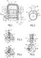
- la figure 1 est une vue en coupe transversale passant par l'axe du système de réglage en hauteur d'une colonne de direction de véhicule automobile munie d'un dispositif de rappel selon l'invention;
- la figure 2 est une vue suivant II de la figure 1;
- la figure 3 est une coupe transversale partielle analogue à la figure 1, d'un autre mode de réalisation de l'invention avant encliquetage dans l'élément d'accrochage;
- la figure 4 est une coupe analogue à la figure 3 après encliquetage dans l'élément d'accrochage;
- la figure 5 est une vue en perspective correspondante à la figure 3;
- le figure 6 est une vue en coupe transversale d'un autre mode de réalisation de l'invention;
- la figure 7 est une vue en perspective du détail de l'accrochage d'une des attaches représentées sur la figure 6;
- la figure 8 est une vue en perspective du mode de réalisation de l'élément élastique représenté sur les figures 1 et 2;
- la figure 9 est une vue semblable à la figure 7 d'un autre mode de réalisation de l'invention ;
- la figure 10 est une vue en perspective d'un autre mode de réalisation de l'élément élastique suivant l'invention;
- la figure 11 est une vue en coupe transversale d'un autre mode de réalisation de l'invention; et
- la figure 12 est une vue longitudinale correspondant à la figure 11.
Claims (15)
- Dispositif de rappel de colonne de direction de véhicule automobile comportant un arbre de direction (1) monté libre en rotation dans un tube-corps (2), qui est disposé dans un élément support (4) fixé au châssis du véhicule, ledit tube-corps (2) étant bloqué à la position voulue par un système de réglage en hauteur (5), caractérisé en ce que ledit dispositif de rappel est constitué par un élément élastique et souple (10) à profil adaptable à l'environnement qui est muni d'un ensemble d'accrochage.
- Dispositif de rappel selon la revendication 1, caractérisé en ce que l'élément élastique 10 est monté sur l'élément support (4), qui est entouré en partie par ledit élément élastique (10), dont le système d'accrochage disposé à chacune de ses extrémités, coopère avec un élément de l'ensemble mobile en hauteur.
- Dispositif de rappel selon la revendication 1, caractérisé en ce que l'élément élastique est disposé sous l'ensemble mobile en hauteur, qui est entouré par ledit élément élastique (10), dont le système d'accrochage disposé à chacune de ses extrémités, coopère avec l'élément support (4).
- Dispositif de rappel selon la revendication 1, caractérisé en ce que l'élément élastique 10 est disposé sous l'ensemble mobile en hauteur, qui est entouré par ledit élément élastique (10), dont le système d'accrochage coopère avec l'élément support (4).
- Dispositif de rappel selon la revendication 2, caractérisé en ce que le système d'accrochage est constitué par une attache 12 ou 13 réalisé sous la forme d'une boucle (17) à double largeur, qui est disposée dans l'extrémité correspondante de l'élément élastique (10), la boucle (17) comportant une entrée circulaire (18) de grand diamètre, qui se prolonge par une partie circulaire d'accrochage (19) de plus petit diamètre; la boucle (17) étant constituée par un fil dont chaque extrémité est munie d'un crochet 20 prolongeant l'entrée circulaire (18), et se faisant face l'un l'autre de manière à pouvoir s'engager dans l'extrémité correspondante de l'élément élastique (10).
- Dispositif de rappel selon la revendication 2, caractérisé en ce que le système d'accrochage est constitué par une attache 12 ou 13 réalisée sous la forme d'une pièce (29) en matière plastique surmoulée sur l'extrémité correspondante de l'élément élastique (10), ladite pièce (29) comportant un crochet (30) d'amarrage.
- Dispositif de rappel selon la revendication 2, caractérisé en ce que le système d'accrochage est constitué par une attache 12 ou 13 réalisée sous la forme d'une pièce (29) métallique fixée sur l'extrémité correspondante de l'élément élastique (10), ladite pièce (29) comportant un crochet (30) d'amarrage.
- Dispositif de rappel selon la revendication 2, caractérisé en ce que le système d'accrochage est constitué par une attache 12 ou 13 réalisée sous la forme d'une pièce (14) en matière plastique surmoulée sur l'extrémité correspondante de l'élément élastique (10), ladite pièce (14) comportant une lumière à double largeur formée par une entrée circulaire (15) de grand diamètre, qui se prolonge par une partie circulaire d'accrochage (16) de plus petit diamètre.
- Dispositif de rappel selon la revendication 3, caractérisé en ce que le système d'accrochage est constitué par une attache réalisée par un fil (31), dont la partie centrale est disposée dans l'extrémité correspondante de l'élément élastique (10), ladite partie centrale se prolongeant de chaque côté par un crochet (32) muni d'un retour (33).
- Dispositif de rappel selon la revendication 3, caractérisé en ce que le système d'accrochage est constitué par une attache réalisée par un fil (31), dont la partie centrale est disposée dans l'extrémité correspondante de l'élément élastique (10), dont l'âme (11) est surmoulée sur la partie centrale, ladite partie centrale se prolongeant de chaque côté par un crochet (32) muni d'un retour (33).
- Dispositif de rappel selon les revendications 2 et 5, caractérisé en ce que l'élément élastique (10), qui est monté sur l'élément support (4), à chacune de ses attaches 12 ou 13, qui est constituée par la boucle (17) à double largeur; la boucle (17) de l'attache 12 s'engageant dans une gorge (24) aménagée dans un élément d'accrochage (22), la boucle (17) de l'attache (13) s'engageant dans une gorge (25) aménagée dans un élément d'accrochage (23), les éléments d'accrochage (22, 23) étant montés sur la vis (6) du système de réglage en hauteur (5).
- Dispositif de rappel selon les revendications 2 et 6, caractérisé en ce que l'élément élastique (10), qui est monté sur l'élément support (4), à chacune de ses attaches (12, 13), qui est constitué par la pièce (29) munie d'un crochet (30), chacune desdites pièces (29) s'engageant dans un logement (27) aménagé dans un élément d'accrochage (26) muni d'une ouverture (28) débouchant dans ledit logement (27), de manière que le crochet (30) vienne rentrer et s'amarrer dans ladite ouverture (28), les éléments d'accrochage (26) étant montés sur la vis (6) du système de réglage en hauteur (5).
- Dispositif de rappel selon les revendications 3 et 9, caractérisé en ce que l'élément élastique (10), qui est disposé sous l'ensemble mobile en hauteur, à chacune de ses attaches (12, 13), qui est constituée par le fil (31), dont la partie centrale est disposée dans l'extrémité correspondante de l'élément élastique (10), ladite partie centrale se prolongeant de chaque côté par un crochet (32) muni d'un retour (33) de manière à venir s'amarrer sur une face (35) sensiblement horizontale d'une excroissance (34) aménagée sur l'élément support (4).
- Dispositif de rappel selon la revendication 4, caractérisé en ce que l'élément élastique (10), qui est disposé sous l'ensemble mobile en hauteur, est un élément sans fin , dont l'ensemble d'accrochage est constitué par un crochet (36) agencé sur l'élément support 4 pour retenir la partie supérieure dudit élément élastique (10).
- Dispositif de rappel selon l'une quelconque des revendications 1 à 3, caractérisé en ce que l'élément élastique (10) a son âme (11) qui est constituée par deux éléments solidarisés à chacun des deux systèmes d'accrochage.
Applications Claiming Priority (2)
| Application Number | Priority Date | Filing Date | Title |
|---|---|---|---|
| FR9612226A FR2754234B1 (fr) | 1996-10-04 | 1996-10-04 | Dispositif de rappel de colonne de direction de vehicule automobile |
| FR9612226 | 1996-10-04 |
Publications (1)
| Publication Number | Publication Date |
|---|---|
| EP0834438A1 true EP0834438A1 (fr) | 1998-04-08 |
Family
ID=9496446
Family Applications (1)
| Application Number | Title | Priority Date | Filing Date |
|---|---|---|---|
| EP97402084A Ceased EP0834438A1 (fr) | 1996-10-04 | 1997-09-05 | Dispositif de rappel de colonne de direction de véhicule automobile |
Country Status (2)
| Country | Link |
|---|---|
| EP (1) | EP0834438A1 (fr) |
| FR (1) | FR2754234B1 (fr) |
Cited By (2)
| Publication number | Priority date | Publication date | Assignee | Title |
|---|---|---|---|---|
| WO2003101807A1 (fr) | 2002-06-04 | 2003-12-11 | Nsk Ltd. | Dispositif de colonne de direction pour véhicule |
| US7354068B2 (en) | 2002-06-04 | 2008-04-08 | Nsk Ltd. | Tilt steering column device for vehicle |
Citations (3)
| Publication number | Priority date | Publication date | Assignee | Title |
|---|---|---|---|---|
| US4648624A (en) * | 1985-09-30 | 1987-03-10 | Cycles Peugeot | Fixing device for a tubular part, in particular for the steering column of a vehicle |
| DE3817764A1 (de) * | 1987-06-05 | 1988-12-22 | Volkswagen Ag | Vorrichtung zur kontinuierlichen hoehenverstellung des lenkradnahen bereichs einer lenksaeule |
| EP0770537A1 (fr) * | 1995-10-27 | 1997-05-02 | Ecia - Equipements Et Composants Pour L'industrie Automobile | Ensemble de colonne de direction réglable pour véhicule automobile |
-
1996
- 1996-10-04 FR FR9612226A patent/FR2754234B1/fr not_active Expired - Fee Related
-
1997
- 1997-09-05 EP EP97402084A patent/EP0834438A1/fr not_active Ceased
Patent Citations (3)
| Publication number | Priority date | Publication date | Assignee | Title |
|---|---|---|---|---|
| US4648624A (en) * | 1985-09-30 | 1987-03-10 | Cycles Peugeot | Fixing device for a tubular part, in particular for the steering column of a vehicle |
| DE3817764A1 (de) * | 1987-06-05 | 1988-12-22 | Volkswagen Ag | Vorrichtung zur kontinuierlichen hoehenverstellung des lenkradnahen bereichs einer lenksaeule |
| EP0770537A1 (fr) * | 1995-10-27 | 1997-05-02 | Ecia - Equipements Et Composants Pour L'industrie Automobile | Ensemble de colonne de direction réglable pour véhicule automobile |
Cited By (5)
| Publication number | Priority date | Publication date | Assignee | Title |
|---|---|---|---|---|
| WO2003101807A1 (fr) | 2002-06-04 | 2003-12-11 | Nsk Ltd. | Dispositif de colonne de direction pour véhicule |
| EP1510434A1 (fr) * | 2002-06-04 | 2005-03-02 | Nsk Ltd., | Dispositif de colonne de direction pour vehicule |
| EP1510434A4 (fr) * | 2002-06-04 | 2006-05-10 | Nsk Ltd | Dispositif de colonne de direction pour vehicule |
| US7354068B2 (en) | 2002-06-04 | 2008-04-08 | Nsk Ltd. | Tilt steering column device for vehicle |
| US7500414B2 (en) | 2002-06-04 | 2009-03-10 | Nsk Ltd. | Steering column device for vehicle |
Also Published As
| Publication number | Publication date |
|---|---|
| FR2754234B1 (fr) | 1998-12-24 |
| FR2754234A1 (fr) | 1998-04-10 |
Similar Documents
| Publication | Publication Date | Title |
|---|---|---|
| EP1176082A1 (fr) | Dispositif d'absorption d'énergie modulable à charges pyrotechniques suivant l'axe d'une colonne de direction de véhicule automobile | |
| FR2477085A1 (fr) | Dispositif pour regler une ferrure de ceinture de securite fixee a la carrosserie d'un vehicule | |
| FR2993823A1 (fr) | Module de roue comportant une valve de gonflage elastiquement deformable pour un systeme de surveillance de la pression des pneus | |
| EP0834438A1 (fr) | Dispositif de rappel de colonne de direction de véhicule automobile | |
| FR2834680A1 (fr) | Dispositif de serrage a commande amortie d'une colonne de direction de vehicule automobile | |
| FR3032013A1 (fr) | Organe de fixation, assemblage comportant un tel organe, siege comportant un tel assemblage et procede de fabrication d'un tel assemblage. | |
| EP0777064B1 (fr) | Dispositif limiteur d'effort en traction | |
| EP0816164A1 (fr) | Siège pour véhicule automobile à dossier perfectionné | |
| EP0497636B1 (fr) | Dispositif de fixation d'un pare-chocs de véhicule | |
| FR2986482A1 (fr) | Platine de connexion electrique pour siege de vehicule automobile | |
| FR2870197A1 (fr) | Module frontal de vehicule automobile comportant des moyens de montage temporaire dans une position de montage intermediaire | |
| FR2737691A1 (fr) | Retroviseur exterieur de vehicules automobiles | |
| FR2756787A1 (fr) | Dispositif de montage d'un accoudoir sur une colonne | |
| EP0459849B1 (fr) | Pare-chocs à fixation réglable pour véhicule automobile | |
| EP3601016B1 (fr) | Piece d'habillage de carrosserie de vehicule | |
| FR2922483A1 (fr) | Boucle escamotable pour ceinture de securite. | |
| EP3015318A1 (fr) | Dispositif perfectionné d'absorption de l'énergie d'un choc, notamment pour un véhicule automobile | |
| EP1396383B1 (fr) | Cache-bagages pour véhicule automobile | |
| FR2781749A1 (fr) | Dispositif d'absorption d'energie d'une colonne de direction reglable de vehicule automobile | |
| FR3047929A1 (fr) | Dispositif coulissant, notamment pour pare-soleil de vehicule, et pare-soleil equipe d'un tel dispositif | |
| FR2860760A1 (fr) | Tampon amortisseur de chocs notamment pour vehicule automoboile | |
| WO2005110822A2 (fr) | Dispositif de fixation de boucles de verrouillage de ceintures | |
| FR3024969A1 (fr) | Ensemble comportant une traverse de planche de bord et des supports pour fixer cette traverse a la caisse d' vehicule automobile | |
| FR3129885A1 (fr) | Véhicule doté d’une poignée de virage placée dans une position centrale | |
| FR2855139A1 (fr) | Elements de maintien en position d'une colonne de direction de vehicule automobile |
Legal Events
| Date | Code | Title | Description |
|---|---|---|---|
| PUAI | Public reference made under article 153(3) epc to a published international application that has entered the european phase |
Free format text: ORIGINAL CODE: 0009012 |
|
| 17P | Request for examination filed |
Effective date: 19970913 |
|
| AK | Designated contracting states |
Kind code of ref document: A1 Designated state(s): DE ES GB IT |
|
| AX | Request for extension of the european patent |
Free format text: AL;LT;LV;RO;SI |
|
| AKX | Designation fees paid |
Free format text: DE ES GB IT |
|
| RBV | Designated contracting states (corrected) |
Designated state(s): DE ES GB IT |
|
| 17Q | First examination report despatched |
Effective date: 19991122 |
|
| GRAG | Despatch of communication of intention to grant |
Free format text: ORIGINAL CODE: EPIDOS AGRA |
|
| STAA | Information on the status of an ep patent application or granted ep patent |
Free format text: STATUS: THE APPLICATION HAS BEEN REFUSED |
|
| 18R | Application refused |
Effective date: 20020128 |