EP0834002B1 - Axialverschiebbares dampfturbinenventil - Google Patents
Axialverschiebbares dampfturbinenventil Download PDFInfo
- Publication number
- EP0834002B1 EP0834002B1 EP96919637A EP96919637A EP0834002B1 EP 0834002 B1 EP0834002 B1 EP 0834002B1 EP 96919637 A EP96919637 A EP 96919637A EP 96919637 A EP96919637 A EP 96919637A EP 0834002 B1 EP0834002 B1 EP 0834002B1
- Authority
- EP
- European Patent Office
- Prior art keywords
- steam
- main axis
- flow passage
- turbine component
- component according
- Prior art date
- Legal status (The legal status is an assumption and is not a legal conclusion. Google has not performed a legal analysis and makes no representation as to the accuracy of the status listed.)
- Expired - Lifetime
Links
Images

Classifications
-
- F—MECHANICAL ENGINEERING; LIGHTING; HEATING; WEAPONS; BLASTING
- F01—MACHINES OR ENGINES IN GENERAL; ENGINE PLANTS IN GENERAL; STEAM ENGINES
- F01D—NON-POSITIVE DISPLACEMENT MACHINES OR ENGINES, e.g. STEAM TURBINES
- F01D17/00—Regulating or controlling by varying flow
- F01D17/10—Final actuators
- F01D17/12—Final actuators arranged in stator parts
- F01D17/14—Final actuators arranged in stator parts varying effective cross-sectional area of nozzles or guide conduits
- F01D17/141—Final actuators arranged in stator parts varying effective cross-sectional area of nozzles or guide conduits by means of shiftable members or valves obturating part of the flow path
- F01D17/145—Final actuators arranged in stator parts varying effective cross-sectional area of nozzles or guide conduits by means of shiftable members or valves obturating part of the flow path by means of valves, e.g. for steam turbines
Definitions
- the invention relates to a steam turbine component as well a steam turbine with one essentially along one Main axis, in particular the main axis of the turbine, displaceable Throttle device for regulating the steam flow through a flow passage which is in a separating element it is provided that in a perpendicular to the main axis Cross-sectional area this is arranged to fill.
- the invention further relates to a method for regulation the steam flow in a steam turbine with a throttle body.
- Axial and radial flows are possible forms of rotary slide valves Called slider.
- the sliders serve that complete or partial blockage of openings that in a running across the cross section of the steam turbine Nozzle covers are provided.
- a first form of a slide consists of a ring rotatable in the circumferential direction, the openings analogous to the openings of the nozzle cover and is flowed through axially, the openings of the slide in axial direction, i.e. in the direction of the main axis of the steam turbine be flowed through.
- a rotatable ring In a second form too a rotatable ring is provided, but in a radial Is flowed through, the openings in the nozzle cover a deflection of the flow from radial in cause axial direction.
- the slide is large on a corresponding deflection part of the nozzle cover on. A movement of the slide must therefore against one considerable frictional resistance take place.
- a third Embodiment are radially displaceable ring segments provided through which the openings in the nozzle cover can be closed are.
- the fourth embodiment is radial flow-through slide valve with an axially displaceable ring described, the nozzle cover in turn a die Flow deflecting stem on which the axially displaceable Ring is performed.
- Throttle control does provide complete static relief possible, but must ensure a free Thermal expansion a relatively large radial gap can be provided. As a result, the opening is completely closed of the nozzle cover not possible, so loss of casualness due to undesirable steam flow have to.
- the object of the invention is therefore a steam turbine component with a throttle to regulate the Specify steam flow, the throttle program for the Use in a turbine for high extraction steam pressures suitable is.
- a steam turbine component Object achieved in that a separating element, which in a perpendicular to the main axis of the steam turbine component extending cross-sectional area arranged to fill is and at least one flow passage for Has flow of steam, and along the main axis Slidable throttle device for regulating the steam flow are provided through the flow passage, wherein the throttle element has a first sealing surface and a second one Has sealing surface, and in a closing the flow passage Position the sealing surfaces on the separating element fit tightly and at least the flow passage partially open position the sealing surfaces of the Separating element are spaced.
- the separating element has one Flow passage away from the cross-sectional area is stretched along the major axis and essentially one parallel to and from the cross-sectional area has spaced wall.
- The is on this wall first sealing surface at a flow passage closing position of the throttle body.
- In the The second position lies in the flow passage closing position Sealing surface also in the cross-sectional area on the separating element on.
- a throttle body which is axially displaceable and in a the flow passage of the separating element, in particular this is a circular opening with intermediate ones Web in a nozzle cover, closing position abuts the separating element and each other the flow passage partially or fully opening position is spaced from the separator, the disadvantages known rotary valve avoided.
- the wear avoided by frictional contact with the separating element, a complete shut-off of the flow passage or at multiple flow passages a complete closure the latter reached, causing undesirable steam flow losses are avoided.
- By avoiding frictional contacts with large actuators are also not required for the separating element.
- both sealing surfaces are preferably in direct contact with the separating element in the cross-sectional plane.
- the first sealing surface preferably bears on the wall described above and the second sealing surface bears directly on the separating element in the cross-sectional area.
- the sealing surfaces are preferably designed as thin-walled circular rings. As a result, the sealing surface is quasi linear, so that there are essentially no frictional contacts with the separating element, but a high level of tightness is nevertheless achieved.
- the throttle element is therefore preferably a circular double seat ring which is arranged centrally to the main axis.
- the central arrangement means that the center of the annulus, viewed in cross-section, coincides with the main axis.
- the guide bolts are preferably eccentric bolts.
- An eccentric bolt has two full cylinders, for example circular cross section, each along a Axis are stretched and fixed on adjacent end faces are interconnected. The direction of the axes are included identical, with only the one full cylinder opposite the other, i.e. eccentrically arranged is. As a result, an exact guidance of the throttle body in reached the turbine housing, which also for example Manufacturing tolerances can be compensated.
- the throttle element preferably has at least one displacement groove on, especially three displacement grooves that both stretched in the axial direction as well as in the circumferential direction is, i.e. runs diagonally to the main axis.
- Shift groove preferably engages in the circumferential direction rotatable rotating ring, in particular via a control pin, on.
- the steam turbine component is preferably provided with a throttle element in a steam turbine, especially in a steam turbine with high extraction steam pressure.
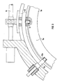
- FIG. 1 shows a section of a steam turbine in one Longitudinal section at the beginning of the low pressure part in front of the area the low-pressure blading shown.
- the one around a major axis 1 rotationally symmetrical steam turbine has a turbine housing 9, which encloses the turbine rotor 17.
- the Cross-sectional area 2 of the steam turbine between the turbine rotor 17 and turbine housing 9 is of a separating element 3, one so-called window ring, filled.
- the separating element 3 has a flow passage 4, which is formed from a " annular opening 18 with intermediate webs in Separating element 3, one stretched in the direction of the main axis 1 Sleeve 16 and an annular wall 8.
- the sleeve 16 is on the separating element 3 directly in the vicinity of the Opening 18, on the side facing the turbine rotor 17 attached.
- the annular wall 8 is with the sleeve 16 tightly connected and is facing away from the turbine rotor 17 Side of the sleeve 16.
- the wall 8 is thus in shape an annular collar on the sleeve 16 so that one parallel to the separating element 8 extending surface spaced therefrom is formed.
- an axially displaceable throttle element 5 is arranged between flow passage 4 and turbine housing 9.
- Guide bolts 11a, 11b are fastened in the turbine housing 9, each in a plane perpendicular to the main axis 1 are stretched. On the circumference of the turbine housing 9 are each at least three pairs of the guide bolts 11a, 11b attached. The illustrated guide bolts 11a, 11b are against each other offset so that they each in a corresponding groove 10a, 10b of the throttle body 5 engage.
- the throttle body 5 has a throttle sleeve extending along the main axis 1 19 and two spaced-apart annular Web 20a, 20b, which on the turbine rotor 17 facing Side of the throttle sleeve 19 attached and from this to the main axis 1 are stretched out.
- the throttle body 5 is one rotating ring 13 running on the circumference of the turbine housing 9 in the direction of the main axis 1, i.e. slidable in the axial direction.
- the webs 20a, 20b each engage axially Throttle lugs stretched towards the separating element 3 21a, 21b.
- the throttle nose 20a forms a first circular ring-shaped one Sealing surface 6 and the throttle nose 21b a second Annular sealing surface 7.
- the first sealing surface 6 lies on the wall 8 and the second sealing surface 7 immediately on the separating element 3 in an area between the turbine housing 9 and the opening 18. This is a tight seal the flow path 4 reached.
- a sleeve-like throttle collar 15a, 15b On the wall 8 as well on the separating element 3 is a sleeve-like throttle collar 15a, 15b attached, each in the axial direction is directed away from the cross-sectional area 2.
- the throttle lugs 21a, 21b of the throttle body 5 and the flow passage 4 assigned throttle collars 15a, 15b thus directly one above the other.
- This is the ratio between steam flow and that along the main axis 1 performed stroke of throttling 5 can be specified.
- the throttle body 5 also shown in dashed lines Position shown in which the first sealing surface 6 and the second sealing surface 7 each from the wall 8 or the separating element 3 are spaced so that the Flow passage 4 for a flow of steam at least is partially released.
- a rotation takes place through the rotating ring 13 Displacement of the throttle body 5 in the axial direction, so that of a complete closure of the flow passage 4 until the flow passage 4 is completely opened the steam throughput through the separating element 3 can be regulated.
- By suspending the throttle element 5 in grooves 10a, 10b guided guide pin 11a, 11b is both a central, i.e. to the main axis 1 symmetrical suspension of the throttle body 5 as well as free thermal expansion guaranteed.
- the extent of the throttle element 5 can largely be freely selected, so that even complete relief from steam forces is possible is.
- both the separating element 3 with the flow passage 4, the rotating ring 13 and the throttle body 5 each from matching semicircular segments composed.
- the double seat ring 5a has three pairs of guide grooves 10a, 10b, each along the major axis 1, i.e. in the axial direction, are directed.
- the pairs of guide grooves 10a, 10b are distributed symmetrically over the circumference of the double seat ring 5a, only a couple is shown for the sake of clarity is.
- There is a displacement groove between the guide grooves 10a, 10b 12 is provided, which is opposite the main axis 1 runs obliquely. A total of three displacement grooves are around the circumference 12 provided.
- the guide grooves 10a, 10b serve to suspend the throttling member 5a via corresponding ones Guide bolts 11a, 11b, which in the guide grooves 10a, 10b engage and fastened in the turbine housing 9 are.
- the guide bolts 11a, 11b are as shown in FIG 3 designed as an eccentric bolt, whereby an exact Alignment of the double seat ring 5a to the main axis 1 reached is.
- In the displacement grooves 12 engages on the circumference of the Turbine housing 9 extending rotary ring 13, so that over a rotation of the rotating ring 13 a displacement of the throttle member 5 is reached in the axial direction.
- FIG 3 shows a section of the steam turbine according to FIG a cross section in which a trained as an eccentric Guide pin 11a, the rotating ring 13, the throttle body 5 (the double seat ring 5a) and a drive 14 for the rotating ring 13 are shown.
- the rotary ring 13 has control bolts which are elongated in the radial direction 22 on, the respective displacement grooves 12 of the Throttle device 5 intervene. Are preferably in the circumferential direction three pairs of guide bolts 11a, 11b and a corresponding one Number of guide grooves 10a, 10b and displacement grooves 12 provided.
- the invention is characterized by an axial direction moveable throttle body, which has two sealing surfaces has, each at two spaced apart Boundary walls extending in the cross-sectional direction of a steam turbine of a flow passage seal this.
- the sealing surfaces are designed so that a movement of the throttle organ opening the flow passage almost no friction forces can be overcome.
- the throttle body is heat-mobile via several guide pins and to the main axis the steam turbine suspended centrally.
- About the scope of the throttling member oblique to the main axis displacement grooves is a displacement of the throttle organ in the direction the main axis. This is done via an in Rotary rotating ring, which has at least one, preferably three, control pin that fits into a corresponding one Sliding groove engages.
- the throttle body is suitable preferably for any adjustable throttling of steam flows through a ring and centrically to the turbine axis arranged openings in front of the low pressure part of Steam turbines. It is particularly useful in overpressure turbines and suitable for high extraction steam pressures.
Landscapes
- Engineering & Computer Science (AREA)
- Mechanical Engineering (AREA)
- General Engineering & Computer Science (AREA)
- Turbine Rotor Nozzle Sealing (AREA)
- Control Of Turbines (AREA)
Applications Claiming Priority (3)
| Application Number | Priority Date | Filing Date | Title |
|---|---|---|---|
| DE19522359 | 1995-06-20 | ||
| DE1995122359 DE19522359C1 (de) | 1995-06-20 | 1995-06-20 | Dampfturbinenkomponente mit Drosselorgan zur Regulierung der Dampfströmung |
| PCT/DE1996/001011 WO1997001020A1 (de) | 1995-06-20 | 1996-06-10 | Axialverschiebbares dampfturbinenventil |
Publications (2)
| Publication Number | Publication Date |
|---|---|
| EP0834002A1 EP0834002A1 (de) | 1998-04-08 |
| EP0834002B1 true EP0834002B1 (de) | 2001-08-22 |
Family
ID=7764782
Family Applications (1)
| Application Number | Title | Priority Date | Filing Date |
|---|---|---|---|
| EP96919637A Expired - Lifetime EP0834002B1 (de) | 1995-06-20 | 1996-06-10 | Axialverschiebbares dampfturbinenventil |
Country Status (5)
| Country | Link |
|---|---|
| EP (1) | EP0834002B1 (fa) |
| JP (1) | JP3889809B2 (fa) |
| DE (2) | DE19522359C1 (fa) |
| IN (1) | IN189232B (fa) |
| WO (1) | WO1997001020A1 (fa) |
Families Citing this family (1)
| Publication number | Priority date | Publication date | Assignee | Title |
|---|---|---|---|---|
| DE102008024254B4 (de) | 2008-05-20 | 2020-03-19 | Man Energy Solutions Se | Ventil für eine Entnahme-Dampfturbine und Entnahme-Dampfturbine mit einem solchen Ventil |
Family Cites Families (5)
| Publication number | Priority date | Publication date | Assignee | Title |
|---|---|---|---|---|
| US2847186A (en) * | 1953-01-12 | 1958-08-12 | Harvey Machine Co Inc | Fluid driven power unit |
| CH428775A (de) * | 1965-09-24 | 1967-01-31 | Escher Wyss Ag | Dampf- oder Gasturbine |
| DE1426792C3 (de) * | 1965-12-02 | 1974-10-03 | Aeg-Kanis Turbinenfabrik Gmbh, 8500 Nuernberg | Überströmventil einer Dampfoder Gasturbine |
| FR2255523A1 (en) * | 1973-12-20 | 1975-07-18 | Marcoux Bernard | Annular flow fluid control valve - has sliding cylindrical valve element sealing on central plug |
| ES2101576T3 (es) * | 1993-10-29 | 1997-07-01 | Siemens Ag | Servomotor, especialmente para una valvula de cierre rapido. |
-
1995
- 1995-06-20 DE DE1995122359 patent/DE19522359C1/de not_active Expired - Fee Related
-
1996
- 1996-06-10 DE DE59607540T patent/DE59607540D1/de not_active Expired - Fee Related
- 1996-06-10 JP JP50350797A patent/JP3889809B2/ja not_active Expired - Fee Related
- 1996-06-10 EP EP96919637A patent/EP0834002B1/de not_active Expired - Lifetime
- 1996-06-10 WO PCT/DE1996/001011 patent/WO1997001020A1/de not_active Ceased
- 1996-06-17 IN IN1119CA1996 patent/IN189232B/en unknown
Also Published As
| Publication number | Publication date |
|---|---|
| WO1997001020A1 (de) | 1997-01-09 |
| IN189232B (fa) | 2003-01-11 |
| DE59607540D1 (de) | 2001-09-27 |
| DE19522359C1 (de) | 1996-08-14 |
| EP0834002A1 (de) | 1998-04-08 |
| JPH11508014A (ja) | 1999-07-13 |
| JP3889809B2 (ja) | 2007-03-07 |
Similar Documents
| Publication | Publication Date | Title |
|---|---|---|
| EP0932780B1 (de) | Einplatten-schieber, insbesondere einplatten-rohrbrückenschieber | |
| DE69426601T2 (de) | Axial öffnendes zylindrisches abblasventil | |
| DE1955438C2 (de) | Ventilmechanismus | |
| EP0568909B1 (de) | Dampfturbine mit einem Drehschieber | |
| DE69217946T2 (de) | Rückführventil | |
| DE69518887T2 (de) | Spreizender Plattenschieber | |
| DE3503434A1 (de) | Regelventil | |
| DE4425344C2 (de) | Drehschieber mit mindestens einem Axialnadeldrehkranz als drehbewegliches Lagerelement | |
| DD224381A5 (de) | Absperrschieber | |
| EP0195178B1 (de) | Durchgangs- und Absperrventil | |
| DE2062292A1 (de) | Dichtung fur ein Durchfluß Steuerventil | |
| EP0834002B1 (de) | Axialverschiebbares dampfturbinenventil | |
| DE2113415C3 (de) | Absperrschieber | |
| EP4027042A1 (de) | Kfz-wegeventil zum einstellen einer fluidströmung | |
| EP0808992B1 (de) | Radialdrehschieber zur Steuerung des Dampfdurchsatzes bei einer Dampfturbine | |
| EP0479021B1 (de) | Stellventil für dampfförmige oder flüssige Medien | |
| DE102014108997A1 (de) | Hochtemperaturventil für eine Verbrennungskraftmaschine | |
| DE3741120A1 (de) | Drosselventil | |
| DE4214773A1 (de) | Dampfturbine mit einem Drehschieber zur Steuerung des Dampfdurchsatzes | |
| CH626145A5 (en) | Gate valve | |
| DE2637217A1 (de) | Absperrschieber mit zweiteiliger schieberzunge | |
| DE3224011C2 (fa) | ||
| EP3489460B1 (de) | Ventil für eine dampfturbine | |
| EP3425246A1 (de) | Ventil | |
| DE3344011C2 (fa) |
Legal Events
| Date | Code | Title | Description |
|---|---|---|---|
| PUAI | Public reference made under article 153(3) epc to a published international application that has entered the european phase |
Free format text: ORIGINAL CODE: 0009012 |
|
| 17P | Request for examination filed |
Effective date: 19971204 |
|
| AK | Designated contracting states |
Kind code of ref document: A1 Designated state(s): CH DE FR GB LI SE |
|
| GRAG | Despatch of communication of intention to grant |
Free format text: ORIGINAL CODE: EPIDOS AGRA |
|
| GRAG | Despatch of communication of intention to grant |
Free format text: ORIGINAL CODE: EPIDOS AGRA |
|
| GRAH | Despatch of communication of intention to grant a patent |
Free format text: ORIGINAL CODE: EPIDOS IGRA |
|
| 17Q | First examination report despatched |
Effective date: 20001128 |
|
| GRAH | Despatch of communication of intention to grant a patent |
Free format text: ORIGINAL CODE: EPIDOS IGRA |
|
| GRAA | (expected) grant |
Free format text: ORIGINAL CODE: 0009210 |
|
| AK | Designated contracting states |
Kind code of ref document: B1 Designated state(s): CH DE FR GB LI SE |
|
| REG | Reference to a national code |
Ref country code: CH Ref legal event code: NV Representative=s name: SIEMENS SCHWEIZ AG Ref country code: CH Ref legal event code: EP |
|
| REF | Corresponds to: |
Ref document number: 59607540 Country of ref document: DE Date of ref document: 20010927 |
|
| GBT | Gb: translation of ep patent filed (gb section 77(6)(a)/1977) |
Effective date: 20011117 |
|
| REG | Reference to a national code |
Ref country code: GB Ref legal event code: IF02 |
|
| ET | Fr: translation filed | ||
| PLBE | No opposition filed within time limit |
Free format text: ORIGINAL CODE: 0009261 |
|
| STAA | Information on the status of an ep patent application or granted ep patent |
Free format text: STATUS: NO OPPOSITION FILED WITHIN TIME LIMIT |
|
| 26N | No opposition filed | ||
| REG | Reference to a national code |
Ref country code: CH Ref legal event code: PCAR Free format text: SIEMENS SCHWEIZ AG;INTELLECTUAL PROPERTY FREILAGERSTRASSE 40;8047 ZUERICH (CH) |
|
| PGFP | Annual fee paid to national office [announced via postgrant information from national office to epo] |
Ref country code: SE Payment date: 20090604 Year of fee payment: 14 Ref country code: FR Payment date: 20090616 Year of fee payment: 14 |
|
| PGFP | Annual fee paid to national office [announced via postgrant information from national office to epo] |
Ref country code: GB Payment date: 20090608 Year of fee payment: 14 Ref country code: DE Payment date: 20090821 Year of fee payment: 14 Ref country code: CH Payment date: 20090903 Year of fee payment: 14 |
|
| REG | Reference to a national code |
Ref country code: CH Ref legal event code: PL |
|
| EUG | Se: european patent has lapsed | ||
| GBPC | Gb: european patent ceased through non-payment of renewal fee |
Effective date: 20100610 |
|
| REG | Reference to a national code |
Ref country code: FR Ref legal event code: ST Effective date: 20110228 |
|
| PG25 | Lapsed in a contracting state [announced via postgrant information from national office to epo] |
Ref country code: DE Free format text: LAPSE BECAUSE OF NON-PAYMENT OF DUE FEES Effective date: 20110101 Ref country code: CH Free format text: LAPSE BECAUSE OF NON-PAYMENT OF DUE FEES Effective date: 20100630 Ref country code: LI Free format text: LAPSE BECAUSE OF NON-PAYMENT OF DUE FEES Effective date: 20100630 |
|
| PG25 | Lapsed in a contracting state [announced via postgrant information from national office to epo] |
Ref country code: FR Free format text: LAPSE BECAUSE OF NON-PAYMENT OF DUE FEES Effective date: 20100630 |
|
| PG25 | Lapsed in a contracting state [announced via postgrant information from national office to epo] |
Ref country code: GB Free format text: LAPSE BECAUSE OF NON-PAYMENT OF DUE FEES Effective date: 20100610 |
|
| PG25 | Lapsed in a contracting state [announced via postgrant information from national office to epo] |
Ref country code: SE Free format text: LAPSE BECAUSE OF NON-PAYMENT OF DUE FEES Effective date: 20100611 |