EP0834002B1 - Axially sliding steam turbine valve - Google Patents
Axially sliding steam turbine valve Download PDFInfo
- Publication number
- EP0834002B1 EP0834002B1 EP96919637A EP96919637A EP0834002B1 EP 0834002 B1 EP0834002 B1 EP 0834002B1 EP 96919637 A EP96919637 A EP 96919637A EP 96919637 A EP96919637 A EP 96919637A EP 0834002 B1 EP0834002 B1 EP 0834002B1
- Authority
- EP
- European Patent Office
- Prior art keywords
- steam
- main axis
- flow passage
- turbine component
- component according
- Prior art date
- Legal status (The legal status is an assumption and is not a legal conclusion. Google has not performed a legal analysis and makes no representation as to the accuracy of the status listed.)
- Expired - Lifetime
Links
Images

Classifications
-
- F—MECHANICAL ENGINEERING; LIGHTING; HEATING; WEAPONS; BLASTING
- F01—MACHINES OR ENGINES IN GENERAL; ENGINE PLANTS IN GENERAL; STEAM ENGINES
- F01D—NON-POSITIVE DISPLACEMENT MACHINES OR ENGINES, e.g. STEAM TURBINES
- F01D17/00—Regulating or controlling by varying flow
- F01D17/10—Final actuators
- F01D17/12—Final actuators arranged in stator parts
- F01D17/14—Final actuators arranged in stator parts varying effective cross-sectional area of nozzles or guide conduits
- F01D17/141—Final actuators arranged in stator parts varying effective cross-sectional area of nozzles or guide conduits by means of shiftable members or valves obturating part of the flow path
- F01D17/145—Final actuators arranged in stator parts varying effective cross-sectional area of nozzles or guide conduits by means of shiftable members or valves obturating part of the flow path by means of valves, e.g. for steam turbines
Definitions
- the invention relates to a steam turbine component as well a steam turbine with one essentially along one Main axis, in particular the main axis of the turbine, displaceable Throttle device for regulating the steam flow through a flow passage which is in a separating element it is provided that in a perpendicular to the main axis Cross-sectional area this is arranged to fill.
- the invention further relates to a method for regulation the steam flow in a steam turbine with a throttle body.
- Axial and radial flows are possible forms of rotary slide valves Called slider.
- the sliders serve that complete or partial blockage of openings that in a running across the cross section of the steam turbine Nozzle covers are provided.
- a first form of a slide consists of a ring rotatable in the circumferential direction, the openings analogous to the openings of the nozzle cover and is flowed through axially, the openings of the slide in axial direction, i.e. in the direction of the main axis of the steam turbine be flowed through.
- a rotatable ring In a second form too a rotatable ring is provided, but in a radial Is flowed through, the openings in the nozzle cover a deflection of the flow from radial in cause axial direction.
- the slide is large on a corresponding deflection part of the nozzle cover on. A movement of the slide must therefore against one considerable frictional resistance take place.
- a third Embodiment are radially displaceable ring segments provided through which the openings in the nozzle cover can be closed are.
- the fourth embodiment is radial flow-through slide valve with an axially displaceable ring described, the nozzle cover in turn a die Flow deflecting stem on which the axially displaceable Ring is performed.
- Throttle control does provide complete static relief possible, but must ensure a free Thermal expansion a relatively large radial gap can be provided. As a result, the opening is completely closed of the nozzle cover not possible, so loss of casualness due to undesirable steam flow have to.
- the object of the invention is therefore a steam turbine component with a throttle to regulate the Specify steam flow, the throttle program for the Use in a turbine for high extraction steam pressures suitable is.
- a steam turbine component Object achieved in that a separating element, which in a perpendicular to the main axis of the steam turbine component extending cross-sectional area arranged to fill is and at least one flow passage for Has flow of steam, and along the main axis Slidable throttle device for regulating the steam flow are provided through the flow passage, wherein the throttle element has a first sealing surface and a second one Has sealing surface, and in a closing the flow passage Position the sealing surfaces on the separating element fit tightly and at least the flow passage partially open position the sealing surfaces of the Separating element are spaced.
- the separating element has one Flow passage away from the cross-sectional area is stretched along the major axis and essentially one parallel to and from the cross-sectional area has spaced wall.
- The is on this wall first sealing surface at a flow passage closing position of the throttle body.
- In the The second position lies in the flow passage closing position Sealing surface also in the cross-sectional area on the separating element on.
- a throttle body which is axially displaceable and in a the flow passage of the separating element, in particular this is a circular opening with intermediate ones Web in a nozzle cover, closing position abuts the separating element and each other the flow passage partially or fully opening position is spaced from the separator, the disadvantages known rotary valve avoided.
- the wear avoided by frictional contact with the separating element, a complete shut-off of the flow passage or at multiple flow passages a complete closure the latter reached, causing undesirable steam flow losses are avoided.
- By avoiding frictional contacts with large actuators are also not required for the separating element.
- both sealing surfaces are preferably in direct contact with the separating element in the cross-sectional plane.
- the first sealing surface preferably bears on the wall described above and the second sealing surface bears directly on the separating element in the cross-sectional area.
- the sealing surfaces are preferably designed as thin-walled circular rings. As a result, the sealing surface is quasi linear, so that there are essentially no frictional contacts with the separating element, but a high level of tightness is nevertheless achieved.
- the throttle element is therefore preferably a circular double seat ring which is arranged centrally to the main axis.
- the central arrangement means that the center of the annulus, viewed in cross-section, coincides with the main axis.
- the guide bolts are preferably eccentric bolts.
- An eccentric bolt has two full cylinders, for example circular cross section, each along a Axis are stretched and fixed on adjacent end faces are interconnected. The direction of the axes are included identical, with only the one full cylinder opposite the other, i.e. eccentrically arranged is. As a result, an exact guidance of the throttle body in reached the turbine housing, which also for example Manufacturing tolerances can be compensated.
- the throttle element preferably has at least one displacement groove on, especially three displacement grooves that both stretched in the axial direction as well as in the circumferential direction is, i.e. runs diagonally to the main axis.
- Shift groove preferably engages in the circumferential direction rotatable rotating ring, in particular via a control pin, on.
- the steam turbine component is preferably provided with a throttle element in a steam turbine, especially in a steam turbine with high extraction steam pressure.
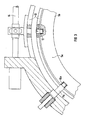
- FIG. 1 shows a section of a steam turbine in one Longitudinal section at the beginning of the low pressure part in front of the area the low-pressure blading shown.
- the one around a major axis 1 rotationally symmetrical steam turbine has a turbine housing 9, which encloses the turbine rotor 17.
- the Cross-sectional area 2 of the steam turbine between the turbine rotor 17 and turbine housing 9 is of a separating element 3, one so-called window ring, filled.
- the separating element 3 has a flow passage 4, which is formed from a " annular opening 18 with intermediate webs in Separating element 3, one stretched in the direction of the main axis 1 Sleeve 16 and an annular wall 8.
- the sleeve 16 is on the separating element 3 directly in the vicinity of the Opening 18, on the side facing the turbine rotor 17 attached.
- the annular wall 8 is with the sleeve 16 tightly connected and is facing away from the turbine rotor 17 Side of the sleeve 16.
- the wall 8 is thus in shape an annular collar on the sleeve 16 so that one parallel to the separating element 8 extending surface spaced therefrom is formed.
- an axially displaceable throttle element 5 is arranged between flow passage 4 and turbine housing 9.
- Guide bolts 11a, 11b are fastened in the turbine housing 9, each in a plane perpendicular to the main axis 1 are stretched. On the circumference of the turbine housing 9 are each at least three pairs of the guide bolts 11a, 11b attached. The illustrated guide bolts 11a, 11b are against each other offset so that they each in a corresponding groove 10a, 10b of the throttle body 5 engage.
- the throttle body 5 has a throttle sleeve extending along the main axis 1 19 and two spaced-apart annular Web 20a, 20b, which on the turbine rotor 17 facing Side of the throttle sleeve 19 attached and from this to the main axis 1 are stretched out.
- the throttle body 5 is one rotating ring 13 running on the circumference of the turbine housing 9 in the direction of the main axis 1, i.e. slidable in the axial direction.
- the webs 20a, 20b each engage axially Throttle lugs stretched towards the separating element 3 21a, 21b.
- the throttle nose 20a forms a first circular ring-shaped one Sealing surface 6 and the throttle nose 21b a second Annular sealing surface 7.
- the first sealing surface 6 lies on the wall 8 and the second sealing surface 7 immediately on the separating element 3 in an area between the turbine housing 9 and the opening 18. This is a tight seal the flow path 4 reached.
- a sleeve-like throttle collar 15a, 15b On the wall 8 as well on the separating element 3 is a sleeve-like throttle collar 15a, 15b attached, each in the axial direction is directed away from the cross-sectional area 2.
- the throttle lugs 21a, 21b of the throttle body 5 and the flow passage 4 assigned throttle collars 15a, 15b thus directly one above the other.
- This is the ratio between steam flow and that along the main axis 1 performed stroke of throttling 5 can be specified.
- the throttle body 5 also shown in dashed lines Position shown in which the first sealing surface 6 and the second sealing surface 7 each from the wall 8 or the separating element 3 are spaced so that the Flow passage 4 for a flow of steam at least is partially released.
- a rotation takes place through the rotating ring 13 Displacement of the throttle body 5 in the axial direction, so that of a complete closure of the flow passage 4 until the flow passage 4 is completely opened the steam throughput through the separating element 3 can be regulated.
- By suspending the throttle element 5 in grooves 10a, 10b guided guide pin 11a, 11b is both a central, i.e. to the main axis 1 symmetrical suspension of the throttle body 5 as well as free thermal expansion guaranteed.
- the extent of the throttle element 5 can largely be freely selected, so that even complete relief from steam forces is possible is.
- both the separating element 3 with the flow passage 4, the rotating ring 13 and the throttle body 5 each from matching semicircular segments composed.
- the double seat ring 5a has three pairs of guide grooves 10a, 10b, each along the major axis 1, i.e. in the axial direction, are directed.
- the pairs of guide grooves 10a, 10b are distributed symmetrically over the circumference of the double seat ring 5a, only a couple is shown for the sake of clarity is.
- There is a displacement groove between the guide grooves 10a, 10b 12 is provided, which is opposite the main axis 1 runs obliquely. A total of three displacement grooves are around the circumference 12 provided.
- the guide grooves 10a, 10b serve to suspend the throttling member 5a via corresponding ones Guide bolts 11a, 11b, which in the guide grooves 10a, 10b engage and fastened in the turbine housing 9 are.
- the guide bolts 11a, 11b are as shown in FIG 3 designed as an eccentric bolt, whereby an exact Alignment of the double seat ring 5a to the main axis 1 reached is.
- In the displacement grooves 12 engages on the circumference of the Turbine housing 9 extending rotary ring 13, so that over a rotation of the rotating ring 13 a displacement of the throttle member 5 is reached in the axial direction.
- FIG 3 shows a section of the steam turbine according to FIG a cross section in which a trained as an eccentric Guide pin 11a, the rotating ring 13, the throttle body 5 (the double seat ring 5a) and a drive 14 for the rotating ring 13 are shown.
- the rotary ring 13 has control bolts which are elongated in the radial direction 22 on, the respective displacement grooves 12 of the Throttle device 5 intervene. Are preferably in the circumferential direction three pairs of guide bolts 11a, 11b and a corresponding one Number of guide grooves 10a, 10b and displacement grooves 12 provided.
- the invention is characterized by an axial direction moveable throttle body, which has two sealing surfaces has, each at two spaced apart Boundary walls extending in the cross-sectional direction of a steam turbine of a flow passage seal this.
- the sealing surfaces are designed so that a movement of the throttle organ opening the flow passage almost no friction forces can be overcome.
- the throttle body is heat-mobile via several guide pins and to the main axis the steam turbine suspended centrally.
- About the scope of the throttling member oblique to the main axis displacement grooves is a displacement of the throttle organ in the direction the main axis. This is done via an in Rotary rotating ring, which has at least one, preferably three, control pin that fits into a corresponding one Sliding groove engages.
- the throttle body is suitable preferably for any adjustable throttling of steam flows through a ring and centrically to the turbine axis arranged openings in front of the low pressure part of Steam turbines. It is particularly useful in overpressure turbines and suitable for high extraction steam pressures.
Abstract
Description
Die Erfindung betrifft eine Dampfturbinenkomponente sowie eine Dampfturbine mit einem im wesentlichen entlang einer Hauptachse, insbesondere der Hauptachse der Turbine, verschieblichen Drosselorgan zur Regulierung der Dampfströmung durch einen Strömungsdurchgang, welcher in einem Trennelement vorgesehen ist, daß in einer senkrecht zur Hauptachse verlaufenden Querschnittsfläche diese ausfüllend angeordnet ist. Die Erfindung betrifft weiterhin ein Verfahren zur Regulierung der Dampfströmung in einer Dampfturbine mit einem Drosselorgan.The invention relates to a steam turbine component as well a steam turbine with one essentially along one Main axis, in particular the main axis of the turbine, displaceable Throttle device for regulating the steam flow through a flow passage which is in a separating element it is provided that in a perpendicular to the main axis Cross-sectional area this is arranged to fill. The invention further relates to a method for regulation the steam flow in a steam turbine with a throttle body.
Zur Regulierung der Dampfströmung in einer Dampfturbine sind verschiedene Regelorgane bekannt. In dem Artikel "Der Drehschieber als Regelorgan für Entnahme-Dampfturbinen" von K. Speicher und E. Mietsch, Maschinenbautechnik, Berlin, Band 15, Heft 4, 1966, Seiten 185 bis 190, ist eine Gegenüberstellung von Regelorganen, basierend auf Ventilen sowie auf Drehschiebern, beschrieben. Ein weiteres Regelorgan ist aus der Druckschrift DE-A-1 426 792 bekannt.To regulate the flow of steam in a steam turbine various regulatory bodies known. In the article "The rotary valve as regulating device for extraction steam turbines "by K. Speicher and E. Mietsch, mechanical engineering, Berlin, volume 15, Issue 4, 1966, pages 185 to 190, is a comparison of control units, based on valves and on rotary valves, described. Another regulatory body is from the Document DE-A-1 426 792 known.
Als mögliche Formen von Drehschiebern werden axial- und radialdurchströmte Schieber genannt. Die Schieber dienen dem vollständigen oder teilweisen Versperren von Öffnungen, die in einem über den Querschnitt der Dampfturbine verlaufenden Düsendeckel vorgesehen sind. Eine erste Form eines Schiebers besteht aus einem in Umfangsrichtung drehbaren Ring, der Öffnungen analog zu den Öffnungen des Düsendeckels aufweist und axial durchströmt wird, wobei die Öffnungen des Schiebers in axialer Richtung, d.h. in Richtung der Hauptachse der Dampfturbine durchströmt werden. In einer zweiten Form ist ebenfalls ein drehbarer Ring vorgesehen, der allerdings in radialer Richtung durchströmt wird, wobei hierzu die Öffnungen in dem Düsendeckel eine Umlenkung der Strömung von radialer in axialer Richtung bewirken. Der Schieber liegt hierbei großflächig auf einem entsprechenden Umlenkungsteils des Düsendeckels auf. Eine Bewegung des Schiebers muß somit gegen einen erheblichen Reibungswiderstand erfolgen. In einer dritten Ausführungsform sind radial verschiebliche Ringsegmente vorgesehen, durch die die Öffnungen in dem Düsendeckel verschließbar sind. Als vierte Ausführungsform ist ein radial durchströmter Schieber mit einem axial verschieblichen Ring beschrieben, wobei hierin der Düsendeckel wiederum einen die Strömung umlenkenden Vorbau aufweist, auf dem der axial verschiebbare Ring geführt wird. Auch in diesem Fall stellt sich die Problematik von großen Reibkräften, welche überwunden werden müssen. Bei den genannten Radial-Drehschiebern ist bei Drosselregelung zwar eine vollständige statische Entlastung möglich, jedoch muß zur Gewährleistung einer freien Wärmedehnung eine relativ großer Radialspalt vorgesehen werden. Hierdurch ist ein vollständiger Verschluß der Öffnung des Düsendeckels nicht möglich, so daß Lässigkeitsverluste infolge unerwünschter Dampfströmung in Kauf genommen werden müssen.Axial and radial flows are possible forms of rotary slide valves Called slider. The sliders serve that complete or partial blockage of openings that in a running across the cross section of the steam turbine Nozzle covers are provided. A first form of a slide consists of a ring rotatable in the circumferential direction, the openings analogous to the openings of the nozzle cover and is flowed through axially, the openings of the slide in axial direction, i.e. in the direction of the main axis of the steam turbine be flowed through. In a second form too a rotatable ring is provided, but in a radial Is flowed through, the openings in the nozzle cover a deflection of the flow from radial in cause axial direction. The slide is large on a corresponding deflection part of the nozzle cover on. A movement of the slide must therefore against one considerable frictional resistance take place. In a third Embodiment are radially displaceable ring segments provided through which the openings in the nozzle cover can be closed are. The fourth embodiment is radial flow-through slide valve with an axially displaceable ring described, the nozzle cover in turn a die Flow deflecting stem on which the axially displaceable Ring is performed. In this case, too the problem of large friction forces, which are overcome Need to become. In the case of the above-mentioned radial rotary valves Throttle control does provide complete static relief possible, but must ensure a free Thermal expansion a relatively large radial gap can be provided. As a result, the opening is completely closed of the nozzle cover not possible, so loss of casualness due to undesirable steam flow have to.
Bei Einsatz der bekannten Axial-Drehschieber entstehen große Anpreß- und Reibungskräfte, die zu einem entsprechenden Verschleiß der aufeinander gleitenden Teile führen. Für den Betrieb solcher Axial-Drehschieber sind darüber hinaus große Stellantriebe bereitzustellen. Zur Reduzierung der Anpreßkräfte sind komplizierte und aufwendige Konstruktionen mit Entlastungsflächen bekannt. Diese benötigen allerdings einen entsprechenden Platzbedarf in radialer Richtung. Bei Turbinen in Überdruckbauweise sind diese Konstruktionen daher praktisch nicht anwendbar. Aufgrund der bekannten Nachteile erfolgt ein Einsatz von Drehschiebern derzeit allenfalls bei relativ niedrigen Entnahmedampfdrücken. When using the well-known axial rotary valve, large ones arise Contact and friction forces that lead to a corresponding wear of the parts sliding on each other. For the business such axial rotary valves are also large Provide actuators. To reduce the contact pressure are complicated and elaborate constructions with Relief areas known. However, these need one corresponding space requirement in the radial direction. For turbines in overpressure construction, these constructions are therefore practical not applicable. Due to the known disadvantages the use of rotary valves is currently at most relatively low extraction steam pressures.
Aufgabe der Erfindung ist es daher, eine Dampfturbinenkomponente mit einem Drosselorgan zur Regulierung der Dampfströmung anzugeben, wobei das Drosselprogramm für den Einsatz in einer Turbine für hohe Entnahmedampfdrücke geeignet ist.The object of the invention is therefore a steam turbine component with a throttle to regulate the Specify steam flow, the throttle program for the Use in a turbine for high extraction steam pressures suitable is.
Erfindungsgemäß wird die auf eine Dampfturbinenkomponente gerichtete Aufgabe dadurch gelöst, daß ein Trennelement, welches in einer senkrecht zur Hauptachse der Dampfturbinenkomponente verlaufenden Querschnittsfläche diese ausfüllend angeordnet ist und zumindest einen Strömungsdurchgang zur Durchströmung von Dampf aufweist, und ein entlang der Hauptachse verschiebliches Drosselorgan zur Regulierung der Dampfströmung durch den Strömungsdurchgang vorgesehen sind, wobei das Drosselorgan eine erste Dichtfläche und eine zweite Dichtfläche hat, und in einer den Strömungsdurchgang verschließenden Stellung die Dichtflächen an den Trennelement dichtend anliegen und in einer den Strömungsdurchgang zumindest teilweise öffnenden Stellung die Dichtflächen von dem Trennelement beabstandet sind. Das Trennelement hat dabei einen Strömungsdurchgang, der von der Querschnittsfläche weg entlang der Hauptachse gestreckt ist und eine im wesentlichen parallel zur Querschnittsfläche verlaufende und von dieser beabstandete Wandung aufweist. An dieser Wandung liegt die erste Dichtfläche bei einer den Strömungsdurchgang verschließenden Stellung des Drosselorgans an. In der den Strömungsdurchgang verschließenden Stellung liegt die zweite Dichtfläche zudem in der Querschnittsfläche an dem Trennelement an.According to the invention, it is directed towards a steam turbine component Object achieved in that a separating element, which in a perpendicular to the main axis of the steam turbine component extending cross-sectional area arranged to fill is and at least one flow passage for Has flow of steam, and along the main axis Slidable throttle device for regulating the steam flow are provided through the flow passage, wherein the throttle element has a first sealing surface and a second one Has sealing surface, and in a closing the flow passage Position the sealing surfaces on the separating element fit tightly and at least the flow passage partially open position the sealing surfaces of the Separating element are spaced. The separating element has one Flow passage away from the cross-sectional area is stretched along the major axis and essentially one parallel to and from the cross-sectional area has spaced wall. The is on this wall first sealing surface at a flow passage closing position of the throttle body. In the The second position lies in the flow passage closing position Sealing surface also in the cross-sectional area on the separating element on.
Durch ein Drosselorgan, welches axial verschieblich ist und in einer den Strömungsdurchgang des Trennelementes, insbesondere ist dies eine kreisringförmige Öffnung mit zwischenliegenden Stegen in einem Düsendeckel, verschließenden Stellung an dem Trennelement anliegt und jeder anderen den Strömungsdurchgang teilweise oder vollständig öffnenden Stellung von dem Trennelement beabstandet ist, werden die Nachteile bekannter Drehschieber vermieden. Insbesondere ist der Verschleiß durch Reibkontakt mit dem Trennelement vermieden, eine vollständige Absperrung des Strömungsdurchgangs oder bei mehreren Strömungsdurchgängen ein vollständiger Verschluß letzterer erreicht, wodurch unerwünschte Dampfströmungsverluste vermieden sind. Durch Vermeidung von Reibkontakten mit dem Trennelement sind ebenfalls große Stellantriebe nicht erforderlich. Bei Verwendung der Dampfturbinenkomponente in einer Dampfturbine, insbesondere im Niederdruckteil der Dampfturbine, fällt die Hauptachse der Dampfturbinenkomponente mit der Hauptachse der Dampfturbine zusammen.By a throttle body, which is axially displaceable and in a the flow passage of the separating element, in particular this is a circular opening with intermediate ones Web in a nozzle cover, closing position abuts the separating element and each other the flow passage partially or fully opening position is spaced from the separator, the disadvantages known rotary valve avoided. In particular, the wear avoided by frictional contact with the separating element, a complete shut-off of the flow passage or at multiple flow passages a complete closure the latter reached, causing undesirable steam flow losses are avoided. By avoiding frictional contacts with large actuators are also not required for the separating element. When using the steam turbine component in one Steam turbine, especially in the low pressure part of the steam turbine, coincides with the main axis of the steam turbine component the main axis of the steam turbine.
Dadurch, daß der Strömungsdurchgang von der Querschnittsfläche in axialer Richtung gestreckt ist und eine zur Querschnittsfläche parallel verlaufende Wandung hat, erfolgt in dem Strömungsdurchgang ein Umlenken der Strömung von einer radialen Richtung in eine axiale Richtung. Durch das Drosselorgan erfolgt eine Absperrung des Strömungsdurchganges an dem Ende des Strömungsdurchganges in dem die Strömung radial verläuft. Bei Verschluß des Strömungsdurchgangs ist ein eindeutiger Kraftschluß erreichbar, in dem beispielsweise über eine geringe Restdampfkraft das Drosselorgan in die den Strömungsdurchgang verschließende Stellung gedrückt wird.Because the flow passage from the cross-sectional area is stretched in the axial direction and one to the cross-sectional area parallel wall takes place in the flow passage a deflection of the flow from one radial direction in an axial direction. Through the throttle body the flow passage is shut off the end of the flow passage in which the flow is radial runs. When the flow passage is closed, there is a clear one Grasping achievable, for example in the a low residual steam force the throttle body into the flow passage closing position is pressed.
Durch Ausgestaltung des Strömungsdurchganges mit einer Strömungsausbildung
in axialer Richtung oder mit einer Umlenkung
in radialer Richtung erfolgt eine hierzu jeweils angepaßte
Anordnung der Dichtflächen. Bei einem Strömungsdurchgang mit
rein axialer Durchströmung liegen beide Dichtflächen vorzugsweise
unmittelbar an dem Trennelement in der Querschnittsebene
an. Bei einem Strömungsdurchgang, der auch eine radiale
Strömung des Dampfes bedingt, liegt vorzugsweise die
erste Dichtfläche an der oben bezeichneten Wandung und die
zweite Dichtfläche unmittelbar an dem Trennelement in der
Querschnittsfläche an. Die Dichtflächen sind vorzugsweise als
dünnwandige Kreisringe ausgeführt. Hierdurch ist die Dichtfläche
quasi linienförmig, so daß im wesentlichen keine Reibkontakte
mit dem Trennelement bestehen, aber trotzdem eine
hohe Dichtigkeit erzielt wird.
Vorzugsweise ist das Drosselorgan daher ein kreisförmiger
Doppelsitzring, der zentrisch zur Hauptachse angeordnet ist.
Die zentrische Anordnung bedeutet, daß der Mittelpunkt des
Kreisringes in einem Querschnitt betrachtet mit der Hauptachse
zusammenfällt. Damit ist eine einfache Fertigung der
Führungen von einem den Doppelsitzring verschiebenden Drehring
sowie dem Trennelement in einem Turbinengehäuse erreicht.
Insbesondere im Hinblick auf eine einfache Montage
ist der Doppelsitzring aus zwei Halbkreissegmenten zusammengesetzt.
Es ist aber auch ebenfalls denkbar, den Doppelsitzring
aus mehreren Kreissegmenten zusammenzusetzen. Der Doppelsitzring
hat vorzugsweise eine axiale Ausdehnung, die der
axialen Ausdehnung des Strömungsdurchgangs entspricht, und
radial gestreckte Stege, an denen die Dichtflächen angeordnet
sind. Hierdurch sind Undichtigkeiten in Abhängigkeit der
Dampftemperatur weitgehend vermieden.By designing the flow passage with a flow formation in the axial direction or with a deflection in the radial direction, an arrangement of the sealing surfaces adapted to this takes place. In the case of a flow passage with a purely axial flow, both sealing surfaces are preferably in direct contact with the separating element in the cross-sectional plane. In the case of a flow passage, which also requires a radial flow of the steam, the first sealing surface preferably bears on the wall described above and the second sealing surface bears directly on the separating element in the cross-sectional area. The sealing surfaces are preferably designed as thin-walled circular rings. As a result, the sealing surface is quasi linear, so that there are essentially no frictional contacts with the separating element, but a high level of tightness is nevertheless achieved.
The throttle element is therefore preferably a circular double seat ring which is arranged centrally to the main axis. The central arrangement means that the center of the annulus, viewed in cross-section, coincides with the main axis. A simple manufacture of the guides of a rotating ring displacing the double seat ring and the separating element in a turbine housing is thus achieved. In particular with a view to simple assembly, the double seat ring is composed of two semicircular segments. However, it is also conceivable to assemble the double seat ring from several circular segments. The double seat ring preferably has an axial extent which corresponds to the axial extent of the flow passage and radially elongated webs on which the sealing surfaces are arranged. This largely prevents leaks depending on the steam temperature.
Für eine exakte Führung des Drosselorgans sind zumindest zwei, insbesondere drei, parallel zur Hauptachse verlaufende Führungsnuten vorgesehen, in die vorzugsweise je zwei Führungsbolzen eingreifen, welche an dem Gehäuse der Turbine befestigt sind. Durch diese Führungsbolzen, die in die Führungsnuten eingreifen, ist eine zentrische exakte Ausrichtung des Drosselorgans erreichbar sowie eine weitgehend spielfreie Führung des Drosselorgans bei einer axialen Bewegung gegeben.For an exact guidance of the throttle body are at least two, in particular three, parallel to the main axis Guide grooves provided, in each of which preferably two guide pins engage, which is attached to the housing of the turbine are. Through these guide bolts, which are in the guide grooves intervene is a centric exact alignment reachable of the throttle body and a largely free of play Guidance of the throttle body given an axial movement.
Die Führungsbolzen sind vorzugsweise Exzenterbolzen. Ein Exzenterbolzen weist beispielsweise zwei Vollzylinder mit kreisförmigen Querschnitt auf, die jeweils entlang einer Achse gestreckt sind und an benachbarten Stirnflächen fest miteinander verbunden sind. Die Richtung der Achsen sind dabei identisch, wobei lediglich der eine Vollzylinder gegenüber dem anderen versetzt ist, d.h. exzentrisch angeordnet ist. Hierdurch wird eine exakte Führung des Drosselorgans in dem Turbinengehäuse erreicht, wodurch beispielsweise auch Fertigungstoleranzen ausgeglichen werden können.The guide bolts are preferably eccentric bolts. An eccentric bolt has two full cylinders, for example circular cross section, each along a Axis are stretched and fixed on adjacent end faces are interconnected. The direction of the axes are included identical, with only the one full cylinder opposite the other, i.e. eccentrically arranged is. As a result, an exact guidance of the throttle body in reached the turbine housing, which also for example Manufacturing tolerances can be compensated.
Das Drosselorgan weist vorzugsweise zumindest eine Verschiebungsnut auf, insbesondere drei Verschiebungsnuten, die sowohl in axialer Richtung als auch in Umfangsrichtung gestreckt ist, d.h. schräg zur Hauptachse verläuft. In diese Verschiebungsnut greift vorzugsweise ein in Umfangsrichtung drehbarer Drehring, insbesondere über einen Steuerbolzen, ein. Bei einer Drehung des Drehringes in Umfangrichtung erfolgt aufgrund der schräg zur Hauptachse ausgerichteten Verschiebungsnut eine Umsetzung der Drehbewegung des Drehrings in eine Axialbewegung des Drosselorgans. Hierdurch wird auf einfache Art und Weise und unter Aufwendung lediglich geringer Kräfte eine Verschiebung des Drosselorgans in axialer Richtung bewerkstelligt.The throttle element preferably has at least one displacement groove on, especially three displacement grooves that both stretched in the axial direction as well as in the circumferential direction is, i.e. runs diagonally to the main axis. In these Shift groove preferably engages in the circumferential direction rotatable rotating ring, in particular via a control pin, on. When the rotating ring is turned in the circumferential direction due to the displacement groove aligned obliquely to the main axis an implementation of the rotating movement of the rotating ring in an axial movement of the throttle member. This will turn on simple way and with less effort Forces a displacement of the throttle element in the axial Direction accomplished.
Vorzugsweise wird die Dampfturbinenkomponente mit Drosselorgan in einer Dampfturbine, insbesondere in einer Dampfturbine mit hohem Entnahmedampfdruck, verwendet.The steam turbine component is preferably provided with a throttle element in a steam turbine, especially in a steam turbine with high extraction steam pressure.
Anhand der in der Zeichnung gezeigten schematisch Ausführungsbeispiele wird die Dampfturbine mit verschieblichem Drosselorgan sowie das Verfahren zur Regulierung des Dampfdurchsatzes in einer Dampfturbine näher erläutert. Es zeigen:
- FIG 1
- einen Längsschnitt durch eine Dampfturbine mit einem Drosselorgan,
- FIG 2
- eine Draufsicht auf das Drosselorgan gemäß FIG 1 und
- FIG 3
- einen Querschnitt der Dampfturbine gemäß FIG 1.
- FIG. 1
- a longitudinal section through a steam turbine with a throttle body,
- FIG 2
- a plan view of the throttle body according to FIG 1 and
- FIG 3
- 2 shows a cross section of the steam turbine according to FIG. 1.
In FIG 1 ist ein Ausschnitt einer Dampfturbine in einem
Längsschnitt am Beginn des Niederdruckteils vor dem Bereich
der Niederdruckbeschaufelung dargestellt. Die um eine Hauptachse
1 rotationssymmetrische Dampfturbine hat ein Turbinengehäuse
9, welches den Turbinenläufer 17 umschließt. Die
Querschnittsfläche 2 der Dampfturbine zwischen Turbinenläufer
17 und Turbinengehäuse 9 ist von einem Trennelement 3, einem
sogenannten Fensterring, ausgefüllt. Das Trennelement 3 weist
einen Strömungsdurchgang 4 auf, der gebildet ist aus einer "
kreisringförmigen Öffnung 18 mit zwischenliegenden Stegen im
Trennelement 3, einer in Richtung der Hauptachse 1 gestreckten
Hülse 16 und einer kreisringförmigen Wandung 8. Die Hülse
16 ist an den Trennelement 3 unmittelbar in der Umgebung der
Öffnung 18, an der dem Turbinenläufer 17 zugewandten Seite
befestigt. Die kreisringförmige Wandung 8 ist mit der Hülse
16 dicht verbunden und liegt auf dem Turbinenläufer 17 abgewandten
Seite der Hülse 16. Die Wandung 8 steht somit in Form
eines Ringkragens auf der Hülse 16, so daß eine parallel zu
dem Trennelement 8 verlaufende von diesem beabstandete Fläche
gebildet ist. Zwischen Strömungsdurchgang 4 und Turbinengehäuse
9 ist ein axial verschiebliches Drosselorgan 5 angeordnet.1 shows a section of a steam turbine in one
Longitudinal section at the beginning of the low pressure part in front of the area
the low-pressure blading shown. The one around a major axis
1 rotationally symmetrical steam turbine has a
In dem Turbinengehäuse 9 sind Führungsbolzen 11a, 11b befestigt,
die in jeweils einer Ebene senkrecht zur Hauptachse 1
gestreckt sind. Am Umfang des Turbinengehäuses 9 sind jeweils
zumindest drei Paare der Führungsbolzen 11a, 11b befestigt.
Die dargestellten Führungsbolzen 11a, 11b sind gegeneinander
versetzt, so daß sie jeweils in eine entsprechende Nut 10a,
10b des Drosselorgans 5 eingreifen. Das Drosselorgan 5 hat
eine entlang der Hauptachse 1 gestreckt verlaufende Drosselhülse
19 sowie zwei voneinander beabstandete kreisringförmige
Stege 20a, 20b, die an der dem Turbinenläufer 17 zugewandten
Seite der Drosselhülse 19 befestigt und von dieser zur Hauptachse
1 hin gestreckt sind. Das Drosselorgan 5 ist über einen
am Umfang des Turbinengehäuses 9 verlaufenden Drehringes 13
in Richtung der Hauptachse 1, d.h. in axialer Richtung, verschieblich.
An den Stegen 20a, 20b greifen jeweils in axialer
Richtung zu dem Trennelement 3 hin gestreckte Drosselnasen
21a, 21b an. Die Drosselnase 20a bildet eine erste kreisrincförmige
Dichtfläche 6 und die Drosselnase 21b eine zweite
kreisringförmige Dichtfläche 7. Die erste Dichtfläche 6 liegt
an der Wandung 8 an und die zweite Dichtfläche 7 unmittelbar
an dem Trennelement 3 in einem Bereich zwischen dem Turbinengehäuse
9 und der Öffnung 18. Hierdurch ist ein dichter Verschluß
des Strömungsweges 4 erreicht. An der Wandung 8 sowie
an dem Trennelement 3 ist jeweils ein hülsenartiger Drosselkragen
15a, 15b befestigt, welcher jeweils in axialer Richtung
von der Querschnittsfläche 2 weggerichtet ist. Die Drosselnasen
21a, 21b des Drosselorgans 5 sowie die dem Strömungsdurchgang
4 zugeordneten Drosselkragen 15a, 15b liegen
somit unmittelbar übereinander. Hierdurch ist das Verhältnis
zwischen Dampfdurchsatz und dem entlang der Hauptachse 1
durchgeführten Hub der Drosselvorgang 5 vorgebbar. Insbesondere
ist eine Linearisierung des Verhältnisses zwischen
Dampfdurchsatz und Hub des Drosselorgans erreichbar. In FIG 1
ist das Drosselorgan 5 zusätzlich in einer strichliert gezeichneten
Position dargestellt, in welcher die erste Dichtfläche
6 sowie die zweite Dichtfläche 7 jeweils von der Wandung
8 bzw. dem Trennelement 3 beabstandet sind, so daß der
Strömungsdurchgang 4 für eine Strömung von Dampf zumindest
teilweise freigegeben ist. Durch den Drehring 13 erfolgt eine
Verschiebung des Drosselorgans 5 in axialer Richtung, so daß
von einem vollständigen Verschluß des Strömungsdurchganges 4
bis zu einem vollständigen Öffnen des Strömungsdurchganges 4
der Dampfdurchsatz durch das Trennelement 3 regelbar ist.
Durch eine Aufhängung des Drosselorgans 5 über in Nuten 10a,
10b geführte Führungsbolzen 11a, 11b ist sowohl eine zentrische,
d.h. zur Hauptachse 1 symmetrische Aufhängung des Drosselorgans
5 sowie eine freie Wärmedehnung gewährleistet. Die
Größe der ersten Dichtungsfläche 6 und der zweiten Dichtungsfläche
7 sowie die Höhe der Stege 20a, 20b, d.h. die radiale
Ausdehnung des Drosselorgans 5 sind weitgehend frei wählbar,
so daß selbst eine völlige Entlastung von Dampfkräften möglich
ist. Zur Vereinfachung der Montage sind sowohl das Trennelement
3 mit dem Strömungsdurchgang 4, der Drehring 13 sowie
das Drosselorgan 5 aus jeweils passenden Halbkreissegmenten
zusammengesetzt.
FIG 2 zeigt ein wie in FIG 1 beschriebenes und als Doppelsitzring
5a ausgebildetes Drosselorgan 5 in einer Draufsicht.
Der Doppelsitzring 5a hat drei Paar Führungsnuten 10a, 10b,
die jeweils entlang der Hauptachse 1, d.h. in axialer Richtung,
gerichtet sind. Die Paare der Führungsnuten 10a, 10b
sind symmetrisch über den Umfang des Doppelsitzrings 5a verteilt,
wobei der Übersichtlichkeit halber nur ein Paar dargestellt
ist. Zwischen den Führungsnuten 10a, 10b ist eine Verschiebungsnut
12 vorgesehen, die gegenüber der Hauptachse 1
schräg verläuft. Über dem Umfang sind insgesamt drei Verschiebungsnuten
12 vorgesehen. Die Führungsnuten 10a, 10b
dienen der Aufhängung des Drosselorgans 5a über jeweils entsprechende
Führungsbolzen 11a, 11b, die in die Führungsnuten
10a, 10b eingreifen und in dem Turbinengehäuse 9 befestigt
sind. Die Führungsbolzen 11a, 11b sind wie in FIG 3 dargestellt
als Exzenterbolzen ausgebildet, wodurch eine exakte
Ausrichtung des Doppelsitzringes 5a zur Hauptachse 1 erreicht
ist. In die Verschiebungsnuten 12 greift ein am Umfang des
Turbinengehäuses 9 verlaufender Drehring 13 ein, so daß über
eine Drehung des Drehringes 13 eine Verschiebung des Drosselorgans
5 in axialer Richtung erreicht wird.2 shows a as described in FIG 1 and as a
FIG 3 zeigt einen Ausschnitt der Dampfturbine gemäß FIG 1 in
einem Querschnitt, in dem ein als Exzenterbolzen ausgebildeter
Führungsbolzen 11a, der Drehring 13, das Drosselorgan 5
(der Doppelsitzring 5a) sowie ein Antrieb 14 für den Drehring
13 gezeigt sind.3 shows a section of the steam turbine according to FIG
a cross section in which a trained as an
Der Drehring 13 weist in radialer Richtung gestreckte Steuerbolzen
22 auf, die in jeweilige Verschiebungsnuten 12 des
Drosselorgans 5 eingreifen. Vorzugsweise sind in Umfangsrichtung
drei Paar Führungsbolzen 11a, 11b sowie eine entsprechende
Zahl von Führungsnuten 10a, 10b und Verschiebungsnuten
12 vorgesehen.The
Die Erfindung zeichnet sich durch ein in axialer Richtung verschiebliches Drosselorgan aus, welches über zwei Dichtflächen verfügt, die jeweils an zwei voneinander beabstandeten in Querschnittsrichtung einer Dampfturbine verlaufende Begrenzungswände eines Strömungsdurchgangs diesen dichtend abschließen. Die Dichtflächen sind so ausgelegt, daß bei einer den Strömungsdurchgang öffnenden Bewegung des Drosselorgans nahezu keine Reibkräfte zu überwinden sind. Das Drosselorgan ist über mehrere Führungsbolzen wärmebeweglich und zur Hauptachse der Dampfturbine zentrisch aufgehängt. Über am Umfang des Drosselorgans schräg zur Hauptachse verlaufende Verschiebungsnuten ist eine Verschiebung des Drosselorgans in Richtung der Hauptachse erreichbar. Diese erfolgt über einen in Umfangsrichtung drehbaren Drehring, der über zumindest einen, vorzugsweise drei, Steuerbolzen verfügt, der in eine entsprechende Verschiebungsnut eingreift. Das Drosselorgan eignet sich vorzugsweise für eine beliebig einstellbare Drosselung von Dampfströmen durch ringförmig und zentrisch zur Turbinenachse angeordneten Öffnungen vor dem Niederdruckteil von Dampfturbinen. Sie ist besonders bei Überdruckturbinen und für hohe Entnahmedampfdrücke geeignet.The invention is characterized by an axial direction moveable throttle body, which has two sealing surfaces has, each at two spaced apart Boundary walls extending in the cross-sectional direction of a steam turbine of a flow passage seal this. The sealing surfaces are designed so that a movement of the throttle organ opening the flow passage almost no friction forces can be overcome. The throttle body is heat-mobile via several guide pins and to the main axis the steam turbine suspended centrally. About the scope of the throttling member oblique to the main axis displacement grooves is a displacement of the throttle organ in the direction the main axis. This is done via an in Rotary rotating ring, which has at least one, preferably three, control pin that fits into a corresponding one Sliding groove engages. The throttle body is suitable preferably for any adjustable throttling of steam flows through a ring and centrically to the turbine axis arranged openings in front of the low pressure part of Steam turbines. It is particularly useful in overpressure turbines and suitable for high extraction steam pressures.
Claims (9)
- Steam-turbine component having a main axis (1), a separating element (3) which is arranged in a cross-sectional area (2) so as to fill the latter perpendicularly to the main axis (1) and has at least one flow passage (4) for the throughflow of steam, and having a throttle element (5) displaceable essentially along the main axis (1) and intended for regulating the steam flow through the flow passage (4), the throttle element (5) having a first sealing surface (6) and a second sealing surface (7), the sealing surfaces (6, 7) bearing in a sealing manner against the separating element (3) in a position closing the flow passage (4), and the sealing surfaces (6, 7) being at a distance from the separating element (3) in a position at least partly opening the flow passage (4), the flow passage (4) extending from the cross-sectional area (2) along the main axis (1) and having a wall (8) which runs essentially parallel to the cross-sectional area (2) and is at a distance from the latter and against which the first sealing surface (6) bears in the position closing the flow passage (4), and the second sealing surface (7) bearing directly against the separating element (3) directly in the cross-sectional plane (2) in the position closing the flow passage (4).
- Steam-turbine component according to Claim 1, characterized in that the throttle element (5) is a circular double-seat ring (5a) which is arranged concentrically to the main axis.
- Steam-turbine component according to Claim 1 or 2, characterized in that the double-seat ring (5a) is composed of two semicircular segments (5b, 5c).
- Steam-turbine component according to one of the preceding claims, having a casing (9), characterized in that the throttle element (5) has at least two guide grooves (10a, 10b) which run parallel to the main axis (1) and in which in each case at least one respective guide pin (11a, 11b) engages, the guide pin (11a, 11b) being fastened to the casing (9).
- Steam-turbine component according to Claim 4, characterized in that the guide pins (11a, 11b) are eccentric pins.
- Steam-turbine component according to one of the preceding claims, characterized in that the throttle element (5) has at least one displacement groove (12) which extends both in the circumferential direction and in the direction of the main axis (1).
- Steam-turbine component according to Claim 4, characterized in that a rotary ring (13) engaging in the displacement groove (12) and rotatable in the circumferential direction is provided, and this rotary ring (13), by rotation in the circumferential direction, produces a displacement of the throttle element (5) in the direction of the main axis (1).
- Steam-turbine component according to one of the preceding claims, characterized in that at least one of the sealing surfaces (6, 7) is designed as a thinwalled circular ring.
- Steam turbine having a steam-turbine component according to one of the preceding claims.
Applications Claiming Priority (3)
| Application Number | Priority Date | Filing Date | Title |
|---|---|---|---|
| DE1995122359 DE19522359C1 (en) | 1995-06-20 | 1995-06-20 | Flow regulation component for steam turbine |
| DE19522359 | 1995-06-20 | ||
| PCT/DE1996/001011 WO1997001020A1 (en) | 1995-06-20 | 1996-06-10 | Axially sliding steam turbine valve |
Publications (2)
| Publication Number | Publication Date |
|---|---|
| EP0834002A1 EP0834002A1 (en) | 1998-04-08 |
| EP0834002B1 true EP0834002B1 (en) | 2001-08-22 |
Family
ID=7764782
Family Applications (1)
| Application Number | Title | Priority Date | Filing Date |
|---|---|---|---|
| EP96919637A Expired - Lifetime EP0834002B1 (en) | 1995-06-20 | 1996-06-10 | Axially sliding steam turbine valve |
Country Status (5)
| Country | Link |
|---|---|
| EP (1) | EP0834002B1 (en) |
| JP (1) | JP3889809B2 (en) |
| DE (2) | DE19522359C1 (en) |
| IN (1) | IN189232B (en) |
| WO (1) | WO1997001020A1 (en) |
Families Citing this family (1)
| Publication number | Priority date | Publication date | Assignee | Title |
|---|---|---|---|---|
| DE102008024254B4 (en) | 2008-05-20 | 2020-03-19 | Man Energy Solutions Se | Valve for an extraction steam turbine and extraction steam turbine with such a valve |
Family Cites Families (5)
| Publication number | Priority date | Publication date | Assignee | Title |
|---|---|---|---|---|
| US2847186A (en) * | 1953-01-12 | 1958-08-12 | Harvey Machine Co Inc | Fluid driven power unit |
| CH428775A (en) * | 1965-09-24 | 1967-01-31 | Escher Wyss Ag | Steam or gas turbine |
| DE1426792C3 (en) * | 1965-12-02 | 1974-10-03 | Aeg-Kanis Turbinenfabrik Gmbh, 8500 Nuernberg | Overflow valve of a steam or gas turbine |
| FR2255523A1 (en) * | 1973-12-20 | 1975-07-18 | Marcoux Bernard | Annular flow fluid control valve - has sliding cylindrical valve element sealing on central plug |
| EP0725889B1 (en) * | 1993-10-29 | 1997-04-23 | Siemens Aktiengesellschaft | Controlling motor, in particular for quick-action stop valves |
-
1995
- 1995-06-20 DE DE1995122359 patent/DE19522359C1/en not_active Expired - Fee Related
-
1996
- 1996-06-10 JP JP50350797A patent/JP3889809B2/en not_active Expired - Fee Related
- 1996-06-10 WO PCT/DE1996/001011 patent/WO1997001020A1/en active IP Right Grant
- 1996-06-10 DE DE59607540T patent/DE59607540D1/en not_active Expired - Fee Related
- 1996-06-10 EP EP96919637A patent/EP0834002B1/en not_active Expired - Lifetime
- 1996-06-17 IN IN1119CA1996 patent/IN189232B/en unknown
Also Published As
| Publication number | Publication date |
|---|---|
| DE59607540D1 (en) | 2001-09-27 |
| EP0834002A1 (en) | 1998-04-08 |
| JP3889809B2 (en) | 2007-03-07 |
| IN189232B (en) | 2003-01-11 |
| WO1997001020A1 (en) | 1997-01-09 |
| JPH11508014A (en) | 1999-07-13 |
| DE19522359C1 (en) | 1996-08-14 |
Similar Documents
| Publication | Publication Date | Title |
|---|---|---|
| EP0932780B1 (en) | Single plate slider, especially pipe bridge single plate slider | |
| EP0568909B1 (en) | Rotating disc obturator for steam turbine | |
| DE1955438C2 (en) | Valve mechanism | |
| EP0380754B1 (en) | Force-balanced lift valve | |
| DE3503434A1 (en) | CONTROL VALVE | |
| DE4425344C2 (en) | Rotary vane with at least one axial needle slewing ring as a rotatable bearing element | |
| DD224381A5 (en) | Gate valves | |
| EP0834002B1 (en) | Axially sliding steam turbine valve | |
| EP1979580B1 (en) | Valve of a steam turbine | |
| DE2113415C3 (en) | Gate valve | |
| EP0808992B1 (en) | Rotary slide valve for the control of steam flow to a steam turbine | |
| DE3741120A1 (en) | THROTTLE VALVE | |
| DE4214773A1 (en) | Steam turbine with a rotary valve to control the steam throughput | |
| EP0479021B1 (en) | Servo-valve for vapourous or liquid media | |
| DE3636739A1 (en) | Valve | |
| EP4027042A1 (en) | Motor vehicle directional control valve for adjusting a fluid flow | |
| DE102014108997A1 (en) | High temperature valve for an internal combustion engine | |
| EP3489460B1 (en) | Valve for a steam turbine | |
| EP0195178B1 (en) | Stopping and flowing valve | |
| DE2637217A1 (en) | LOCKING VALVE WITH TWO-PIECE TONGUE | |
| DE3344011C2 (en) | ||
| DE809503C (en) | Slider | |
| DE3224011C2 (en) | ||
| DE3509289C1 (en) | Quick-closing device for flowing media | |
| DE2457960A1 (en) | Closing mechanism for shut off valve - has adjusting sleeve and control piston with singe operating spindle |
Legal Events
| Date | Code | Title | Description |
|---|---|---|---|
| PUAI | Public reference made under article 153(3) epc to a published international application that has entered the european phase |
Free format text: ORIGINAL CODE: 0009012 |
|
| 17P | Request for examination filed |
Effective date: 19971204 |
|
| AK | Designated contracting states |
Kind code of ref document: A1 Designated state(s): CH DE FR GB LI SE |
|
| GRAG | Despatch of communication of intention to grant |
Free format text: ORIGINAL CODE: EPIDOS AGRA |
|
| GRAG | Despatch of communication of intention to grant |
Free format text: ORIGINAL CODE: EPIDOS AGRA |
|
| GRAH | Despatch of communication of intention to grant a patent |
Free format text: ORIGINAL CODE: EPIDOS IGRA |
|
| 17Q | First examination report despatched |
Effective date: 20001128 |
|
| GRAH | Despatch of communication of intention to grant a patent |
Free format text: ORIGINAL CODE: EPIDOS IGRA |
|
| GRAA | (expected) grant |
Free format text: ORIGINAL CODE: 0009210 |
|
| AK | Designated contracting states |
Kind code of ref document: B1 Designated state(s): CH DE FR GB LI SE |
|
| REG | Reference to a national code |
Ref country code: CH Ref legal event code: NV Representative=s name: SIEMENS SCHWEIZ AG Ref country code: CH Ref legal event code: EP |
|
| REF | Corresponds to: |
Ref document number: 59607540 Country of ref document: DE Date of ref document: 20010927 |
|
| GBT | Gb: translation of ep patent filed (gb section 77(6)(a)/1977) |
Effective date: 20011117 |
|
| REG | Reference to a national code |
Ref country code: GB Ref legal event code: IF02 |
|
| ET | Fr: translation filed | ||
| PLBE | No opposition filed within time limit |
Free format text: ORIGINAL CODE: 0009261 |
|
| STAA | Information on the status of an ep patent application or granted ep patent |
Free format text: STATUS: NO OPPOSITION FILED WITHIN TIME LIMIT |
|
| 26N | No opposition filed | ||
| REG | Reference to a national code |
Ref country code: CH Ref legal event code: PCAR Free format text: SIEMENS SCHWEIZ AG;INTELLECTUAL PROPERTY FREILAGERSTRASSE 40;8047 ZUERICH (CH) |
|
| PGFP | Annual fee paid to national office [announced via postgrant information from national office to epo] |
Ref country code: SE Payment date: 20090604 Year of fee payment: 14 Ref country code: FR Payment date: 20090616 Year of fee payment: 14 |
|
| PGFP | Annual fee paid to national office [announced via postgrant information from national office to epo] |
Ref country code: GB Payment date: 20090608 Year of fee payment: 14 Ref country code: DE Payment date: 20090821 Year of fee payment: 14 Ref country code: CH Payment date: 20090903 Year of fee payment: 14 |
|
| REG | Reference to a national code |
Ref country code: CH Ref legal event code: PL |
|
| EUG | Se: european patent has lapsed | ||
| GBPC | Gb: european patent ceased through non-payment of renewal fee |
Effective date: 20100610 |
|
| REG | Reference to a national code |
Ref country code: FR Ref legal event code: ST Effective date: 20110228 |
|
| PG25 | Lapsed in a contracting state [announced via postgrant information from national office to epo] |
Ref country code: DE Free format text: LAPSE BECAUSE OF NON-PAYMENT OF DUE FEES Effective date: 20110101 Ref country code: CH Free format text: LAPSE BECAUSE OF NON-PAYMENT OF DUE FEES Effective date: 20100630 Ref country code: LI Free format text: LAPSE BECAUSE OF NON-PAYMENT OF DUE FEES Effective date: 20100630 |
|
| PG25 | Lapsed in a contracting state [announced via postgrant information from national office to epo] |
Ref country code: FR Free format text: LAPSE BECAUSE OF NON-PAYMENT OF DUE FEES Effective date: 20100630 |
|
| PG25 | Lapsed in a contracting state [announced via postgrant information from national office to epo] |
Ref country code: GB Free format text: LAPSE BECAUSE OF NON-PAYMENT OF DUE FEES Effective date: 20100610 |
|
| PG25 | Lapsed in a contracting state [announced via postgrant information from national office to epo] |
Ref country code: SE Free format text: LAPSE BECAUSE OF NON-PAYMENT OF DUE FEES Effective date: 20100611 |