EP0833717B1 - Verfahren und vorrichtung zum perforieren von bedrucktem mehrschichtverbundmaterial - Google Patents
Verfahren und vorrichtung zum perforieren von bedrucktem mehrschichtverbundmaterial Download PDFInfo
- Publication number
- EP0833717B1 EP0833717B1 EP96920796A EP96920796A EP0833717B1 EP 0833717 B1 EP0833717 B1 EP 0833717B1 EP 96920796 A EP96920796 A EP 96920796A EP 96920796 A EP96920796 A EP 96920796A EP 0833717 B1 EP0833717 B1 EP 0833717B1
- Authority
- EP
- European Patent Office
- Prior art keywords
- laser
- cut sections
- station
- laser station
- stack
- Prior art date
- Legal status (The legal status is an assumption and is not a legal conclusion. Google has not performed a legal analysis and makes no representation as to the accuracy of the status listed.)
- Expired - Lifetime
Links
Images

Classifications
-
- B—PERFORMING OPERATIONS; TRANSPORTING
- B23—MACHINE TOOLS; METAL-WORKING NOT OTHERWISE PROVIDED FOR
- B23K—SOLDERING OR UNSOLDERING; WELDING; CLADDING OR PLATING BY SOLDERING OR WELDING; CUTTING BY APPLYING HEAT LOCALLY, e.g. FLAME CUTTING; WORKING BY LASER BEAM
- B23K26/00—Working by laser beam, e.g. welding, cutting or boring
- B23K26/36—Removing material
- B23K26/38—Removing material by boring or cutting
- B23K26/382—Removing material by boring or cutting by boring
-
- B—PERFORMING OPERATIONS; TRANSPORTING
- B23—MACHINE TOOLS; METAL-WORKING NOT OTHERWISE PROVIDED FOR
- B23K—SOLDERING OR UNSOLDERING; WELDING; CLADDING OR PLATING BY SOLDERING OR WELDING; CUTTING BY APPLYING HEAT LOCALLY, e.g. FLAME CUTTING; WORKING BY LASER BEAM
- B23K26/00—Working by laser beam, e.g. welding, cutting or boring
- B23K26/08—Devices involving relative movement between laser beam and workpiece
- B23K26/083—Devices involving movement of the workpiece in at least one axial direction
- B23K26/0838—Devices involving movement of the workpiece in at least one axial direction by using an endless conveyor belt
-
- B—PERFORMING OPERATIONS; TRANSPORTING
- B23—MACHINE TOOLS; METAL-WORKING NOT OTHERWISE PROVIDED FOR
- B23K—SOLDERING OR UNSOLDERING; WELDING; CLADDING OR PLATING BY SOLDERING OR WELDING; CUTTING BY APPLYING HEAT LOCALLY, e.g. FLAME CUTTING; WORKING BY LASER BEAM
- B23K26/00—Working by laser beam, e.g. welding, cutting or boring
- B23K26/36—Removing material
- B23K26/40—Removing material taking account of the properties of the material involved
-
- B—PERFORMING OPERATIONS; TRANSPORTING
- B23—MACHINE TOOLS; METAL-WORKING NOT OTHERWISE PROVIDED FOR
- B23K—SOLDERING OR UNSOLDERING; WELDING; CLADDING OR PLATING BY SOLDERING OR WELDING; CUTTING BY APPLYING HEAT LOCALLY, e.g. FLAME CUTTING; WORKING BY LASER BEAM
- B23K2103/00—Materials to be soldered, welded or cut
- B23K2103/08—Non-ferrous metals or alloys
- B23K2103/10—Aluminium or alloys thereof
-
- B—PERFORMING OPERATIONS; TRANSPORTING
- B23—MACHINE TOOLS; METAL-WORKING NOT OTHERWISE PROVIDED FOR
- B23K—SOLDERING OR UNSOLDERING; WELDING; CLADDING OR PLATING BY SOLDERING OR WELDING; CUTTING BY APPLYING HEAT LOCALLY, e.g. FLAME CUTTING; WORKING BY LASER BEAM
- B23K2103/00—Materials to be soldered, welded or cut
- B23K2103/16—Composite materials
- B23K2103/166—Multilayered materials
- B23K2103/172—Multilayered materials wherein at least one of the layers is non-metallic
-
- B—PERFORMING OPERATIONS; TRANSPORTING
- B23—MACHINE TOOLS; METAL-WORKING NOT OTHERWISE PROVIDED FOR
- B23K—SOLDERING OR UNSOLDERING; WELDING; CLADDING OR PLATING BY SOLDERING OR WELDING; CUTTING BY APPLYING HEAT LOCALLY, e.g. FLAME CUTTING; WORKING BY LASER BEAM
- B23K2103/00—Materials to be soldered, welded or cut
- B23K2103/30—Organic materials
- B23K2103/40—Paper
-
- B—PERFORMING OPERATIONS; TRANSPORTING
- B23—MACHINE TOOLS; METAL-WORKING NOT OTHERWISE PROVIDED FOR
- B23K—SOLDERING OR UNSOLDERING; WELDING; CLADDING OR PLATING BY SOLDERING OR WELDING; CUTTING BY APPLYING HEAT LOCALLY, e.g. FLAME CUTTING; WORKING BY LASER BEAM
- B23K2103/00—Materials to be soldered, welded or cut
- B23K2103/30—Organic materials
- B23K2103/42—Plastics other than composite materials
-
- B—PERFORMING OPERATIONS; TRANSPORTING
- B23—MACHINE TOOLS; METAL-WORKING NOT OTHERWISE PROVIDED FOR
- B23K—SOLDERING OR UNSOLDERING; WELDING; CLADDING OR PLATING BY SOLDERING OR WELDING; CUTTING BY APPLYING HEAT LOCALLY, e.g. FLAME CUTTING; WORKING BY LASER BEAM
- B23K2103/00—Materials to be soldered, welded or cut
- B23K2103/50—Inorganic materials other than metals or composite materials
Definitions
- the invention relates to a method and a device for making perforations and / or half cuts in printed multi-layer composite material by means of Laser beams of at least one in a laser station arranged laser.
- Multi-layer composite material is used in particular when packaging food in Folding box packs.
- a backing layer is made Cardboard, cardboard or paper and possibly one on it aluminum foil layer on both sides with Layers of polyethylene (PE) provided for later Pack the necessary properties regarding tightness, Oxygen barrier, light protection, etc. Since such known packs are primarily for milk, Juice or the like are used, these packs are in usually provided with a printed image on which information attached to the content, manufacturer, advertising or the like.
- PE polyethylene
- the multi-layer composite material is usually manufactured as web material, the later Pack outside the web with the desired ones Provide print images and transport or on rolls passed on for further use.
- Folding box packs often have lines of weakness in the Backing material and the outer PE layer in order for example inserting drinking straws into the To facilitate packing or to prevent the ingress of To enable pouring aids.
- Such lines of weakness either as perforations or as half cuts (Lines of weakness in one or more Composite material layer (s) are executed, must therefore to be in the "right" place of the later pack to be placed, depending on the printed image in the Composite material are introduced.
- EP 0 357 841 B1 already discloses a Composite material web depending on the printed image to pass a laser station, the control of the laser depending on the previously scanned Print image is done. It can quickly be seen that this process is extremely complex because the Laser treatment is carried out with a moving web and that the movement of the laser beam does not just mean that actual contour of the notch but also the Path speed must take into account.
- GB 21 61 427 A is already a process in itself for processing thermoplastic blanks, e.g. PVC, known in which in these blanks by means of a through a mask guided laser beam fold lines are generated to create a container from this blank fold for packaging purposes. In doing so the PVC blanks for processing Vacuum tables positioned by side guides and then through Vacuum fixed. In contrast, that comes inventive method or the corresponding Device without such a design effort.
- thermoplastic blanks e.g. PVC
- the invention is therefore based on the object Method and device of the type mentioned to design and develop so that the constructive effort especially with regard to Control in the manufacture of perforations and / or Half cuts will be minimized without the exact Positioning the perforations and / or half cuts to have to do without.
- the solution to the problem is that a device for cutting the Multi-layer composite material web in individual cuts, a laser station with at least one laser and appropriate deflection devices to guide each Laser beam and slings, which are arranged perpendicular to the direction of transport Include sling gear for positioning the the individual blanks fed to the laser station in the Level of laser treatment and corresponding transportation and / or Stacking means for the individual cuts.
- the moving is no longer Multi-layer composite material web of laser treatment subjected, but this is first to individual Cut to size, which is then laser treated and then the actual packs getting produced. Because the printing of the composite material mechanically and thus in register, the Composite material web also in register in Blanks cut so that the laser treatment does not more depending on the printed image, but rather in Depending on the cutting edges can be done. To this The design effort is the way inventive method and the corresponding Device significantly less than in the known Processes because of complex print image recognition and a complicated web speed dependent Laser control can be dispensed with.
- the blanks to be treated during the Laser treatment aligned in a horizontal plane.
- gravity is used to plan to let blanks rest on one level so no curvatures, distortions or the like can arise.
- a first embodiment of the invention provides that the individual cuts before laser treatment be stacked that the laser treatment of each cut on top of a stack and that the treated blanks one by one from Stacks are pulled off to the side.
- the individual cuts of the Laser station fed and stacked there the Laser treatment of the top of the stack cutting is done and the below the Laser station emerging stacks down step by step is moved.
- the cuts of the individual Undergo laser treatment it is in a further embodiment of the Invention expedient that the finished blanks behind the laser station are stacked.
- each Laser treatment is initially based on the Available spatial conditions and operational requirements. This is the first Alternative especially if the previously individual blanks are already in stack form, for example, to be transported to the laser station become.
- the second alternative is always special usable if the laser-treated Blanks are to be stacked anyway. This can depending on the operational conditions, the supply of Cuts to the laser station directly or through the use of one or more intermediate stack magazines be done to the printing and cutting process on the one hand and the laser treatment process on the other hand to equalize.
- Intensity of the laser beam used or used laser beams adjustable is especially for the semi-cutting of large Importance because - depending on the training of the Multi-layer composite material - a different thickness local evaporation in one or more layers of the material to be removed is required.
- the three alternatives Process operated such that the slings for the positioning and fixation of those to be treated Blanks are designed so that the laser station has a shaft through which a variety horizontally stacked blanks fed from below is or that the sling is designed so are that the individual blanks of the laser station be fed laterally and that below the Laser station a stack magazine for the finished treated Blanks is arranged.
- a stacking device for the finished treated blanks arranged behind the Laser station a stacking device for the finished treated blanks arranged.
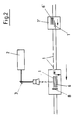
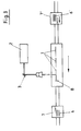
- Blanks 1 of at least one laser beam Laser 2 shown only schematically Deflection devices 3 perforated and / or with Provide half-cut lines.
- the direction of movement of the Cuts 1 is made in all three figures in the direction arrows not shown from right to right Left.
- FIG. 1 In the first variant shown in Fig. 1 takes place the supply of the blanks 1 from below, the each top cut 1 from a height stop 4 is limited to the blank 1 in the focal plane of the Fix laser 2.
- Shaft guide 5 shown schematically that the previously formed from blanks 1 stack 6 such is fed that the blanks 1 in horizontal Direction from the side walls of the shaft guide are surrounded without play.
- FIG blanks 1 treated by laser 2
- Stack former 7 'supplied and there in stacks 6' filed. 1 is also dash-dotted another upstream stack former 7 is shown, which after separating the blanks 1 is used to make stack 6, which is then the actual laser station are supplied.
- the device shown in Fig. 2 differs 1 in that the supply of the blanks 1 takes place laterally in a horizontal plane, with a Side stop 8 ensures that the to be treated Cuts 1 can be fixed without play. This is done stacking the blanks that have already been lasered 1 below the treatment level by gradual Lowering the treated blanks 1.
- Fig. 3 is a third variant of the Device shown according to the invention, in which both the supply as well as the removal of the blanks 1 for Laser station in the horizontal treatment level he follows. Appropriately, this also takes place in one downstream stacking 7 a stack of Cuts 1 to stacks 6, which are for the subsequent Further treatment can be portioned. Here too it can be useful by another one of the laser station upstream stack former 7 'already existing stack 6 'to separate to separate the upstream To achieve printing and cutting devices.
Landscapes
- Engineering & Computer Science (AREA)
- Physics & Mathematics (AREA)
- Optics & Photonics (AREA)
- Plasma & Fusion (AREA)
- Mechanical Engineering (AREA)
- Laser Beam Processing (AREA)
- Control Of Cutting Processes (AREA)
- Making Paper Articles (AREA)
- Manufacturing Of Printed Wiring (AREA)
- Laminated Bodies (AREA)
- Reinforced Plastic Materials (AREA)
Description
- Zerschneiden der Mehrschichtverbundmaterialbahn in einzelne Zuschnitte in Abhängigkeit vom Druckbild und/oder Falzbild,
- Transport der Zuschnitte zur Laserstation,
- Positionierung und Fixierung der Zuschnitte seitlich und in der Ebene der Laserbehandlung mittels Anschlagmitteln, umfassend senkrecht zur Transportrichtung angeordnete Anschlagmittel, und
- Herstellen der Perforations- bzw. Halbschnittlinien bei ruhendem Zuschnitt in Abhängigkeit der Anschläge.
- Fig. 1
- ein erstes Ausführungsbeispiel einer erfindungsgemäßen Vorrichtung in schematischer Darstellung,
- Fig. 2
- ein zweites Ausführungsbeispiel der erfindungsgemäßen Vorrichtung und
- Fig. 3
- ein drittes Ausführungsbeispiel der erfindungsgemäßen Vorrichtung.
Claims (15)
- Verfahren zum Herstellen von Perforationen und/oder Halbschnitten in bedrucktem Mehrschichtverbundmaterial mittels Laserstrahlen wenigstens eines in einer Laserstation angeordneten Lasers, mit folgenden Schritten :Zerschneiden der Mehrschichtverbundmaterialbahn in einzelne Zuschnitte in Abhängigkeit vom Druckbild und/oder Falzbild,Transport der Zuschnitte zur Laserstation,Positionierung und Fixierung der Zuschnitte seitlich und in der Ebene der Laserbehandlung mittels Anschlagmitteln, umfassend senkrecht zur Transportrichtung angeordnete Anschlagmittel, undHerstellen der Perforations- bzw. Halbschnittlinien bei ruhendem Zuschnitt in Abhängigkeit der Anschläge.
- Verfahren nach Anspruch 1,
dadurch gekennzeichnet, daß die zu behandelnden Zuschnitte während der Laserbehandlung in horizontaler Ebene ausgerichtet sind. - Verfahren nach Anspruch 2,
dadurch gekennzeichnet, daß die einzelnen Zuschnitte vor der Laserbehandlung gestapelt werden, daß die Laserbehandlung des jeweils oben auf einem Stapel befindlichen Zuschnitts erfolgt und daß die behandelten Zuschnitte einzeln schrittweise vom Stapel zur Seite abgezogen werden. - Verfahren nach Anspruch 2,
dadurch gekennzeichnet, daß die einzelnen Zuschnitte der Laserstation zugeführt und dort gestapelt werden, die Laserbehandlung des jeweils oben auf dem Stapel befindlichen Zuschnitts erfolgt und der unterhalb der Laserstation entstehende Stapel schrittweise nach unten bewegt wird. - Verfahren nach Anspruch 2,
dadurch gekennzeichnet, daß die Zuschnitte vereinzelt der Laserbehandlung unterzogen werden. - Verfahren nach Anspruch 3,
dadurch gekennzeichnet, daß der Stapel unterhalb der Laserstation schrittweise von unten gegen einen mit seiner Unterkante in der Behandlungsebene des Lasers liegenden Höhenanschlag gefördert werden. - Verfahren nach einem der Ansprüche 3 oder 5,
dadurch gekennzeichnet, daß die fertigen Zuschnitte hinter der Laserstation gestapelt werden. - Verfahren nach einem der Ansprüche 1 bis 7,
dadurch gekennzeichnet, daß die Intensität des verwendeten Laserstrahls einstellbar ist. - Vorrichtung zum Herstellen von Perforationen und/oder Halbschnitten in bedrucktem Mehrschichtverbundmaterial mittels Laserstrahlen nach einem der Verfahren gemäß den Ansprüchen 1 bis 9, mit einer Vorrichtung zum Zerschneiden der Mehrschichtverbundmaterialbahn in einzelne Zuschnitte (1), einer Laserstation mit wenigstens einem Laser (2) und entsprechenden Ablenkeinrichtungen (3) zur Führung jedes Laserstrahls sowie Anschlagmitteln, welche senkrecht zur Transportrichtung angeordnete Anschlagmittel umfassen, zur Positionierung der der Laserstation zugeführten einzelnen Zuschnitte (1) in der Ebene der Laserbehandlung und entsprechenden Transport- und/oder Stapelmitteln für die einzelnen Zuschnitte (1).
- Vorrichtung nach Anspruch 9,
dadurch gekennzeichnet, daß die Laserstation oberhalb der horizontal angeordneten zu behandelnden Zuschnitte (1) auf der Druckseite angeordnet ist. - Vorrichtung nach Anspruch 10,
dadurch gekennzeichnet, daß die Anschlagmittel so ausgebildet sind, daß die Laserstation einen Schacht (6) aufweist, durch den eine Vielzahl horizontal gestapelter Zuschnitte (1) von unten zugeführt wird. - Vorrichtung nach Anspruch 10,
dadurch gekennzeichnet, daß die Anschlagmittel so ausgebildet sind, daß die einzelnen Zuschnitte (1) der Laserstation seitlich zugeführt werden und daß unterhalb der Laserstation ein Stapelmagazin für die fertig behandelten Zuschnitte (1) angeordnet ist. - Vorrichtung nach Anspruch 10,
dadurch gekennzeichnet, daß die Anschlagmittel so ausgebildet sind, daß die einzelnen Zuschnitte (1) der Laserstation in der Behandlungsebene zugeführt und wieder abgeführt werden. - Vorrichtung nach Anspruch 11 oder 12,
dadurch gekennzeichnet, daß hinter der Laserstation eine Stapelvorrichtung für die fertig behandelten Zuschnitte (1) angeordnet ist. - Vorrichtung nach Anspruch 12 oder 13,
dadurch gekennzeichnet, daß vor der Laserstation Mittel zur Stapelung und Vereinzelung der Zuschnitte (1) angeordnet sind.
Applications Claiming Priority (3)
| Application Number | Priority Date | Filing Date | Title |
|---|---|---|---|
| DE19520713 | 1995-06-12 | ||
| DE19520713A DE19520713C2 (de) | 1995-06-12 | 1995-06-12 | Verfahren und Vorrichtung zum Herstellen von Perforationen und/oder Halbschnitten in bedrucktem Mehrschichtverbundmaterial mittels Laserstrahlen |
| PCT/EP1996/002447 WO1996041698A1 (de) | 1995-06-12 | 1996-06-05 | Verfahren und vorrichtung zum perforieren von bedrucktem mehrschichtverbundmaterial |
Publications (2)
| Publication Number | Publication Date |
|---|---|
| EP0833717A1 EP0833717A1 (de) | 1998-04-08 |
| EP0833717B1 true EP0833717B1 (de) | 1999-04-14 |
Family
ID=7763788
Family Applications (1)
| Application Number | Title | Priority Date | Filing Date |
|---|---|---|---|
| EP96920796A Expired - Lifetime EP0833717B1 (de) | 1995-06-12 | 1996-06-05 | Verfahren und vorrichtung zum perforieren von bedrucktem mehrschichtverbundmaterial |
Country Status (6)
| Country | Link |
|---|---|
| US (1) | US6007756A (de) |
| EP (1) | EP0833717B1 (de) |
| AT (1) | ATE178828T1 (de) |
| DE (2) | DE19520713C2 (de) |
| ES (1) | ES2131401T3 (de) |
| WO (1) | WO1996041698A1 (de) |
Families Citing this family (16)
| Publication number | Priority date | Publication date | Assignee | Title |
|---|---|---|---|---|
| JP2001506542A (ja) * | 1996-11-21 | 2001-05-22 | トーマチュージ プティ リミテッド | 改良された物体製造 |
| DE50009122D1 (de) * | 2000-08-19 | 2005-02-03 | Carl Ingolf Lange | Bearbeitungsvorrichtung für flache Bögen |
| US20030124294A1 (en) * | 2001-12-28 | 2003-07-03 | Hodson Jay D. | Scored package and a method of making the same |
| SE519633C2 (sv) * | 2002-03-25 | 2003-03-25 | Tetra Laval Holdings & Finance | Sätt vid tillverkning av ett förpackningslaminat, anläggning vid tillverkningen av förpackningslaminatet, samt det tillverkade förpackningslaminatet |
| US20030231811A1 (en) * | 2002-06-07 | 2003-12-18 | Hodson Jay D. | Internally scored film, package and methods of making the same |
| US7592567B2 (en) * | 2003-09-11 | 2009-09-22 | Wazana Brothers International, Inc. | Apparatus and method for disassembling containers having thermoplastic joining surfaces |
| JP4311158B2 (ja) * | 2003-10-14 | 2009-08-12 | 株式会社デンソー | 樹脂成形品およびその製造方法 |
| US20080156863A1 (en) * | 2006-12-29 | 2008-07-03 | Weyerhaeuser Co. | Systems and methods for improving the readability of printed bar code symbols and the like |
| DE102008038988B3 (de) * | 2008-08-13 | 2009-09-17 | Kraussmaffei Technologies Gmbh | Stanz- und Beschnittvorrichtung für Kunststoffbauteile |
| KR20100107253A (ko) * | 2009-03-25 | 2010-10-05 | 삼성모바일디스플레이주식회사 | 기판 절단 장치 및 이를 이용한 기판 절단 방법 |
| WO2010112449A1 (de) * | 2009-04-03 | 2010-10-07 | Adval Tech Holding Ag | Herstellunsverfahreng von filtern unter verwendung eines laserstrahles mit einstellung des durchmessers des laserstrahles; hergestellter filter; anlage zur durchführung des herstellungsverfahrens |
| US20110070386A1 (en) * | 2009-09-19 | 2011-03-24 | Yoel Wazana | Apparatus And Method For Disassembling Containers Having Thermoplastic Joining Surfaces |
| US8814430B2 (en) * | 2010-02-23 | 2014-08-26 | Kraft Foods R&D, Inc. | Food package having opening feature |
| DE102011103979A1 (de) * | 2011-06-10 | 2012-12-13 | Heidelberger Druckmaschinen Ag | Beschnittvorrichtung zur Bearbeitung eines Bogenstapels und Druckmaschine oder Falzmaschine oder Papierbearbeitungsmaschine mit einer solchen |
| CN103144139B (zh) * | 2013-03-25 | 2015-12-30 | 兰如林 | 适用在布料、皮料以及革料上的打孔机 |
| CN114624957B (zh) * | 2022-03-24 | 2023-08-18 | 青岛天仁微纳科技有限责任公司 | 一种适用于多种形状模板的纳米压印辅助装置 |
Family Cites Families (6)
| Publication number | Priority date | Publication date | Assignee | Title |
|---|---|---|---|---|
| US3790744A (en) * | 1971-07-19 | 1974-02-05 | American Can Co | Method of forming a line of weakness in a multilayer laminate |
| DD120156A1 (de) * | 1975-06-23 | 1976-06-05 | ||
| DE3222394A1 (de) * | 1982-06-15 | 1983-12-15 | Richard Dipl.-Chem. 6000 Frankfurt Kraemer | Verfahren zur herstellung von formatgeschnittenen papierboegen mit glatten schnittraendern |
| GB8415046D0 (en) * | 1984-06-13 | 1984-07-18 | Amalgamated Mining Trading | Forming containers |
| ES2051829T3 (es) * | 1988-09-07 | 1994-07-01 | Leeuwarder Papier | Metodo de proporcionar lineas hendidas en materia de envasado. |
| US5688463A (en) * | 1995-06-12 | 1997-11-18 | Combibloc, Inc. | Laser processing of discrete sheets of material |
-
1995
- 1995-06-12 DE DE19520713A patent/DE19520713C2/de not_active Expired - Lifetime
-
1996
- 1996-06-05 EP EP96920796A patent/EP0833717B1/de not_active Expired - Lifetime
- 1996-06-05 AT AT96920796T patent/ATE178828T1/de active
- 1996-06-05 WO PCT/EP1996/002447 patent/WO1996041698A1/de not_active Ceased
- 1996-06-05 DE DE59601672T patent/DE59601672D1/de not_active Expired - Lifetime
- 1996-06-05 US US08/981,175 patent/US6007756A/en not_active Expired - Lifetime
- 1996-06-05 ES ES96920796T patent/ES2131401T3/es not_active Expired - Lifetime
Also Published As
| Publication number | Publication date |
|---|---|
| EP0833717A1 (de) | 1998-04-08 |
| ATE178828T1 (de) | 1999-04-15 |
| WO1996041698A1 (de) | 1996-12-27 |
| DE19520713A1 (de) | 1996-12-19 |
| DE19520713C2 (de) | 1997-07-03 |
| DE59601672D1 (de) | 1999-05-20 |
| ES2131401T3 (es) | 1999-07-16 |
| US6007756A (en) | 1999-12-28 |
Similar Documents
| Publication | Publication Date | Title |
|---|---|---|
| DE19520713C2 (de) | Verfahren und Vorrichtung zum Herstellen von Perforationen und/oder Halbschnitten in bedrucktem Mehrschichtverbundmaterial mittels Laserstrahlen | |
| EP1437202B1 (de) | Vorrichtung und Verfahren zur Nutzentrennung in einer Maschine zur Herstellung von aus einer Materialbahn ausgeschnittenen Flachmaterialstücken | |
| EP0718096B1 (de) | Verfahren und Vorrichtung zum Herstellen eines Getränkebehälters | |
| EP1043234B1 (de) | Vorrichtung und Verfahren zum Trennen einer Folie mit wenigstens zwei Laminatschichten und Verpackungsmaschine mit einer solchen Vorrichtung | |
| DE3106155C2 (de) | ||
| EP2288559A1 (de) | Vorrichtung und verfahren zum herstellen von einzelzuschnitten aus einer folienbahn | |
| EP0187323A1 (de) | Verfahren und Vorrichtung zum Herstellen von Zuschnitten für Verpackungen | |
| DE3041050A1 (de) | Verfahren zur herstellung von kunststoffbeschichteten fluessigkeitsverpackungen | |
| DE102010051239A1 (de) | Bearbeitungsstation für eine Stanzmaschine und Verfahren zur Probebogenauslage | |
| DE102012019992A1 (de) | Vorrichtung für eine Flachbettstanze und Verfahren zum Zuführen einer Bedruckstoffbahn | |
| EP2145773B1 (de) | Verfahren und Vorrichtung zum Herstellen von mehrblättrigen, gefalzten Druckereierzeugnissen, insbesondere Zeitschriften und Broschüren | |
| DE102011103979A1 (de) | Beschnittvorrichtung zur Bearbeitung eines Bogenstapels und Druckmaschine oder Falzmaschine oder Papierbearbeitungsmaschine mit einer solchen | |
| DE29622554U1 (de) | Teilbare Verpackung, insbesondere Zigarettenkartusche | |
| WO2023169873A1 (de) | Vorrichtung und verfahren zur herstellung von verpackungsbehältnissen | |
| EP0755356B1 (de) | Vorrichtung und verfahren zum zusammenführen und veredeln mehrerer papierbahnen | |
| DE3604870A1 (de) | Verfahren und vorrichtung zum abstapeln von wellpappenabschnitten auf mindestens zwei nebeneinander angeordnete stapel | |
| DE10328868B4 (de) | Verfahren zum Perforieren einer Kaschierfolie in einer Bogenkaschieranlage, Lasertrennvorrichtung hierfür, sowie Bogenkaschieranlage mit einer solchen Lasertrennvorrichtung | |
| DE3110592A1 (de) | "maschine und verfahren zum herstellen wetterfester versandvordrucke" | |
| DE10196951B3 (de) | Verfahren zur Herstellung eines bedruckten Verpackungslaminats und Vorrichtung zur Durchführung des Verfahrens | |
| EP1631449A2 (de) | Verfahren und vorrichtung zum herstellen von packungsmänteln für karton/kunststoff-verbundpackungen | |
| DE69525137T2 (de) | Gehälterverpackungsverfahren und -maschine mit seitigung überschüssiger behälter und darin verwendete führungsschiene | |
| EP0505533B1 (de) | Einrichtung zum entfernen der restbahn | |
| WO2003022694A1 (de) | Behälter für flüssigkeiten und maschine zu seiner herstellung | |
| DE102019125352B4 (de) | Bahnversetzeinrichtung für Etiketten-Druckmaschinen und Etiketten-Verarbeitungsmaschinen | |
| EP0427068A2 (de) | Vorrichtung zur Herstellung von Einlagen für Versandhüllen |
Legal Events
| Date | Code | Title | Description |
|---|---|---|---|
| PUAI | Public reference made under article 153(3) epc to a published international application that has entered the european phase |
Free format text: ORIGINAL CODE: 0009012 |
|
| 17P | Request for examination filed |
Effective date: 19971202 |
|
| AK | Designated contracting states |
Kind code of ref document: A1 Designated state(s): AT CH DE ES FR GB IT LI NL |
|
| GRAG | Despatch of communication of intention to grant |
Free format text: ORIGINAL CODE: EPIDOS AGRA |
|
| 17Q | First examination report despatched |
Effective date: 19980421 |
|
| RAP1 | Party data changed (applicant data changed or rights of an application transferred) |
Owner name: SIG COMBIBLOC GMBH |
|
| GRAG | Despatch of communication of intention to grant |
Free format text: ORIGINAL CODE: EPIDOS AGRA |
|
| GRAH | Despatch of communication of intention to grant a patent |
Free format text: ORIGINAL CODE: EPIDOS IGRA |
|
| GRAH | Despatch of communication of intention to grant a patent |
Free format text: ORIGINAL CODE: EPIDOS IGRA |
|
| GRAA | (expected) grant |
Free format text: ORIGINAL CODE: 0009210 |
|
| AK | Designated contracting states |
Kind code of ref document: B1 Designated state(s): AT CH DE ES FR GB IT LI NL |
|
| REF | Corresponds to: |
Ref document number: 178828 Country of ref document: AT Date of ref document: 19990415 Kind code of ref document: T |
|
| REG | Reference to a national code |
Ref country code: CH Ref legal event code: NV Representative=s name: TROESCH SCHEIDEGGER WERNER AG Ref country code: CH Ref legal event code: EP |
|
| REF | Corresponds to: |
Ref document number: 59601672 Country of ref document: DE Date of ref document: 19990520 |
|
| ET | Fr: translation filed | ||
| GBT | Gb: translation of ep patent filed (gb section 77(6)(a)/1977) |
Effective date: 19990506 |
|
| REG | Reference to a national code |
Ref country code: ES Ref legal event code: FG2A Ref document number: 2131401 Country of ref document: ES Kind code of ref document: T3 |
|
| PLBE | No opposition filed within time limit |
Free format text: ORIGINAL CODE: 0009261 |
|
| STAA | Information on the status of an ep patent application or granted ep patent |
Free format text: STATUS: NO OPPOSITION FILED WITHIN TIME LIMIT |
|
| 26N | No opposition filed | ||
| REG | Reference to a national code |
Ref country code: GB Ref legal event code: IF02 |
|
| REG | Reference to a national code |
Ref country code: GB Ref legal event code: 732E |
|
| REG | Reference to a national code |
Ref country code: FR Ref legal event code: PLFP Year of fee payment: 20 |
|
| PGFP | Annual fee paid to national office [announced via postgrant information from national office to epo] |
Ref country code: GB Payment date: 20150618 Year of fee payment: 20 Ref country code: ES Payment date: 20150618 Year of fee payment: 20 Ref country code: CH Payment date: 20150611 Year of fee payment: 20 Ref country code: DE Payment date: 20150611 Year of fee payment: 20 |
|
| PGFP | Annual fee paid to national office [announced via postgrant information from national office to epo] |
Ref country code: NL Payment date: 20150617 Year of fee payment: 20 Ref country code: AT Payment date: 20150611 Year of fee payment: 20 Ref country code: IT Payment date: 20150619 Year of fee payment: 20 Ref country code: FR Payment date: 20150618 Year of fee payment: 20 |
|
| REG | Reference to a national code |
Ref country code: DE Ref legal event code: R071 Ref document number: 59601672 Country of ref document: DE |
|
| REG | Reference to a national code |
Ref country code: NL Ref legal event code: MK Effective date: 20160604 |
|
| REG | Reference to a national code |
Ref country code: CH Ref legal event code: PL |
|
| REG | Reference to a national code |
Ref country code: GB Ref legal event code: PE20 Expiry date: 20160604 |
|
| REG | Reference to a national code |
Ref country code: AT Ref legal event code: MK07 Ref document number: 178828 Country of ref document: AT Kind code of ref document: T Effective date: 20160605 |
|
| PG25 | Lapsed in a contracting state [announced via postgrant information from national office to epo] |
Ref country code: GB Free format text: LAPSE BECAUSE OF EXPIRATION OF PROTECTION Effective date: 20160604 |
|
| REG | Reference to a national code |
Ref country code: ES Ref legal event code: FD2A Effective date: 20160926 |
|
| PG25 | Lapsed in a contracting state [announced via postgrant information from national office to epo] |
Ref country code: ES Free format text: LAPSE BECAUSE OF EXPIRATION OF PROTECTION Effective date: 20160606 |