EP0833079A2 - Stufenlos regelbares Getriebe - Google Patents
Stufenlos regelbares Getriebe Download PDFInfo
- Publication number
- EP0833079A2 EP0833079A2 EP97307602A EP97307602A EP0833079A2 EP 0833079 A2 EP0833079 A2 EP 0833079A2 EP 97307602 A EP97307602 A EP 97307602A EP 97307602 A EP97307602 A EP 97307602A EP 0833079 A2 EP0833079 A2 EP 0833079A2
- Authority
- EP
- European Patent Office
- Prior art keywords
- assembly
- fluid
- flow
- impeller
- valve
- Prior art date
- Legal status (The legal status is an assumption and is not a legal conclusion. Google has not performed a legal analysis and makes no representation as to the accuracy of the status listed.)
- Withdrawn
Links
- 230000005540 biological transmission Effects 0.000 title claims abstract description 17
- 239000012530 fluid Substances 0.000 claims abstract description 36
- 230000007246 mechanism Effects 0.000 claims description 4
- 230000008878 coupling Effects 0.000 description 10
- 238000010168 coupling process Methods 0.000 description 10
- 238000005859 coupling reaction Methods 0.000 description 10
- 230000007423 decrease Effects 0.000 description 2
- 230000000694 effects Effects 0.000 description 2
- 230000009347 mechanical transmission Effects 0.000 description 1
- 238000012986 modification Methods 0.000 description 1
- 230000004048 modification Effects 0.000 description 1
- 230000003134 recirculating effect Effects 0.000 description 1
- 230000009467 reduction Effects 0.000 description 1
Images


Classifications
-
- F—MECHANICAL ENGINEERING; LIGHTING; HEATING; WEAPONS; BLASTING
- F16—ENGINEERING ELEMENTS AND UNITS; GENERAL MEASURES FOR PRODUCING AND MAINTAINING EFFECTIVE FUNCTIONING OF MACHINES OR INSTALLATIONS; THERMAL INSULATION IN GENERAL
- F16H—GEARING
- F16H47/00—Combinations of mechanical gearing with fluid clutches or fluid gearing
- F16H47/06—Combinations of mechanical gearing with fluid clutches or fluid gearing the fluid gearing being of the hydrokinetic type
- F16H47/08—Combinations of mechanical gearing with fluid clutches or fluid gearing the fluid gearing being of the hydrokinetic type the mechanical gearing being of the type with members having orbital motion
- F16H47/085—Combinations of mechanical gearing with fluid clutches or fluid gearing the fluid gearing being of the hydrokinetic type the mechanical gearing being of the type with members having orbital motion with at least two mechanical connections between the hydrokinetic gearing and the mechanical gearing
-
- F—MECHANICAL ENGINEERING; LIGHTING; HEATING; WEAPONS; BLASTING
- F16—ENGINEERING ELEMENTS AND UNITS; GENERAL MEASURES FOR PRODUCING AND MAINTAINING EFFECTIVE FUNCTIONING OF MACHINES OR INSTALLATIONS; THERMAL INSULATION IN GENERAL
- F16D—COUPLINGS FOR TRANSMITTING ROTATION; CLUTCHES; BRAKES
- F16D33/00—Rotary fluid couplings or clutches of the hydrokinetic type
- F16D33/02—Rotary fluid couplings or clutches of the hydrokinetic type controlled by changing the flow of the liquid in the working circuit, while maintaining a completely filled working circuit
- F16D33/04—Rotary fluid couplings or clutches of the hydrokinetic type controlled by changing the flow of the liquid in the working circuit, while maintaining a completely filled working circuit by altering the position of blades
-
- F—MECHANICAL ENGINEERING; LIGHTING; HEATING; WEAPONS; BLASTING
- F16—ENGINEERING ELEMENTS AND UNITS; GENERAL MEASURES FOR PRODUCING AND MAINTAINING EFFECTIVE FUNCTIONING OF MACHINES OR INSTALLATIONS; THERMAL INSULATION IN GENERAL
- F16H—GEARING
- F16H37/00—Combinations of mechanical gearings, not provided for in groups F16H1/00 - F16H35/00
- F16H37/02—Combinations of mechanical gearings, not provided for in groups F16H1/00 - F16H35/00 comprising essentially only toothed or friction gearings
- F16H37/06—Combinations of mechanical gearings, not provided for in groups F16H1/00 - F16H35/00 comprising essentially only toothed or friction gearings with a plurality of driving or driven shafts; with arrangements for dividing torque between two or more intermediate shafts
- F16H37/08—Combinations of mechanical gearings, not provided for in groups F16H1/00 - F16H35/00 comprising essentially only toothed or friction gearings with a plurality of driving or driven shafts; with arrangements for dividing torque between two or more intermediate shafts with differential gearing
- F16H37/0833—Combinations of mechanical gearings, not provided for in groups F16H1/00 - F16H35/00 comprising essentially only toothed or friction gearings with a plurality of driving or driven shafts; with arrangements for dividing torque between two or more intermediate shafts with differential gearing with arrangements for dividing torque between two or more intermediate shafts, i.e. with two or more internal power paths
- F16H37/084—Combinations of mechanical gearings, not provided for in groups F16H1/00 - F16H35/00 comprising essentially only toothed or friction gearings with a plurality of driving or driven shafts; with arrangements for dividing torque between two or more intermediate shafts with differential gearing with arrangements for dividing torque between two or more intermediate shafts, i.e. with two or more internal power paths at least one power path being a continuously variable transmission, i.e. CVT
- F16H2037/0866—Power-split transmissions with distributing differentials, with the output of the CVT connected or connectable to the output shaft
Definitions
- the present invention relates to a transmission assembly.
- Such automatic transmissions usual embody a combination of hydraulic and mechanical transmission components.
- the hydraulic components include a torque convertor, such as a fluid coupling, whereas the mechanical components include planetary (or epicyclic) gears.
- a fluid coupling typically includes an impeller or driving member, and a runner or driven member, such as a turbine.
- the impeller is rotationally coupled to the engine and is driven by the engine.
- the fluid such as oil
- the oil is deflected against the vanes of the runner back towards the impeller. This re-circulation of oil rotates the runner at increasing rotational speed until it is rotating at the same speed as the impeller.
- the recirculating oil is commonly referred to as "acting" oil.
- a fluid coupling being a type of torque convertor, thus converts the low torque of the rapidly rotating impeller into a high torque on the drive shaft with a low rotational speed.
- This type of coupling transmits the same torque produced by the engine, except for some losses due to "slip" because the runner is not mechanically coupled to the impeller and hence has a small degree of rotational lag.
- a fluid coupling thus provides a smooth transfer of torque from the engine to a drive shaft so that the vehicle moves away smoothly.
- slip may be generally defined as the degree to which the rotating speed of a driven member lags behind the rotating speed of a driving member.
- the present invention has means for varying the flow of oil within the coupling and also the speed of the oil as it leaves the impeller.
- One embodiment uses planetary gears.
- Mechanical planetary gears conventionally comprise a centrally mounted sun gear with one or more planet gears. The planet gears engage with the sun gear and with an outer gear called the ring gear.
- the speed of the impeller can be made indirectly proportional to the quantity of oil flowing within the coupling. As such, the smaller the amount of oil permitted to flow, the greater the speed of the impeller. Hence, the velocity of the oil as it meets the blades of the runner is controllable.
- E the energy contained within the "acting" fluid
- m is the mass of the acting fluid
- V 1 is the velocity of the acting fluid stream leaving the impeller blade
- V 2 is the velocity of the acting fluid after it meets the blade of the runner.
- Acting fluid is defined as the fluid (for example oil) which moves between the blades of the impeller and the blades of the runner.
- a transmission assembly which comprises a driving member, a driven member in fluid communication with the driving member, and flow control means for controlling the flow of fluid within the assembly.
- the fluid control means comprises a valve whereby closing the valve reduces flow of acting fluid in the assembly and opening the valve increases the flow of acting fluid in the assembly.
- the fluid is oil.
- the fluid control means may comprise a stator, wherein the stator has a plurality of blades which are moveable between an open and a closed position.
- the blades allow the flow of acting fluid in the assembly in the open position and restrict the flow of acting fluid in the assembly in the closed position.
- the transmission assembly further includes a driving mechanism.
- the driving mechanism comprises a planetary gear.
- the planetary gear train includes a sun gear which is centrally mounted in the train, one or more planet gears and a ring gear at the outer periphery of the train, wherein the planet gears engage with an outer surface of the sun gear and with an inner surface of the ring gear.
- the planet gears are coupled to an input shaft from an engine.
- the driving member is coupled to the sun gear of the planetary gear train.
- the driven member is coupled to the ring gear of the planetary gear train.
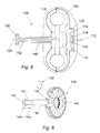
- Fig. 1 shows a transmission assembly 10 which is coupled to an engine (not shown) via an input shaft 12 from the engine.
- the input shaft 12 is connected to a planetary gear carrier 15 which has a plurality of planetary gears 14 mounted thereon, as best shown in Figs 7a and 7b.
- the planetary gears 14 are independently and rotatably mounted on the planetary gear carrier 15.
- a driving member or impeller 16 is coupled to sun gear 18 of the gear train and a driven member or runner 20 is coupled at a first end to ring gear 22.
- the runner 20 is coupled at a second end to output shaft 24 which in turn drives the wheels of the vehicle.
- the first embodiment of the assembly includes a hydraulic portion (the fluid coupling) and a mechanical portion (the planetary gear train).
- the input shaft 12 is rotated by the engine which in turn drives the planetary gear carrier 15 of the gear train.
- the planetary gears 14 rotate due to the rotation of the planetary gear carrier 15 of the gear train assembly and cause rotation of the impeller 16.
- the fluid coupling works on the principle that acting oil is thrown out from the blades of the impeller 16. If the flow of acting oil is restricted, then a very small proportion of oil will be directed towards the blades of the runner 20 and hence the speed of the runner 20 and the ring gear 22 should be about zero. However, due to the engagement of the planetary gears 14 and the ring gear 22, the ring gear 22 will rotate at a slow speed, with the planet gears 14 taking up the slip as the sun gear 18 rotates at a much higher speed.
- the flow of acting oil is controlled by the position of a flow control valve 28.
- the valve 28 In Fig. 1, the valve 28 is shown in the closed position. With the valve 28 closed, the flow of oil in the torque convertor is restricted. In these conditions, the impeller 16 will rotate at a speed which is between 3 and 4 times the speed of the engine input shaft 12, as there will be a reduced quantity of oil to be pumped by the impeller 16.
- the planetary gears are used to permit the impeller 16 to rotate at a higher speed with respect to the runner 20. As the flow of acting oil is reduced and the impeller 16 is rotating at this higher speed, full input torque is transmitted to the output shaft 24.
- the position of the valve 28 is controlled using a bracket 30, which is coupled to a shaft 32 of the valve 28 using, for example, a thrust bearing (not shown).
- the thrust bearing permits the valve 28 to rotate in synchronisation with the impeller 16 whilst allowing the bracket 30 to remain stationary.
- a hydraulic piston for example could be coupled to the bracket 30 and the piston actuated to effect movement of the valve 28.
- the travel of the piston should be in the order of 50 to 100 mm.
- the valve 28 is provided with a plurality of slots 32.
- the slots 32 allow the vanes of the impeller 16 to slide within these slots, thereby closing the valve 28 as shown in Fig. 1.
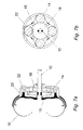
- FIGs 5 and 6 there is shown an alternative transmission assembly 100. Wherever possible, similar features to the previous embodiment have been labelled using the same reference numbers prefixed with a 1.
- a reactor 134 is positioned between the impeller 116 and the runner 120.
- the reactor 134 is provided with a plurality of blades 136 which are rotatable as shown by the arrows 138.
- the shaft 140 of the reactor 134 is provided with a telescopic portion 142 which slides within the shaft 140.
- the blades 136 of the wheel 134 In operation, to restrict the flow of oil between the impeller 116 and the runner 120, the blades 136 of the wheel 134 will be turned to prevent passage of oil. In this shut-off position, the telescopic portion 142 of the shaft 140 moves towards the blades in the direction of arrow 144c. The telescopic portion 142 acts against a plurality of control gears 146 which are coupled to the blades 136, thereby controlling the position of the blades 136.
- the over-all operation of the transmission assembly 100 is the same as that for the previous embodiment and hence a detailed description will be omitted.
- the only difference in the assembly 100 is the use of the moveable blades 136 to control the oil flow as opposed to the use of the valve 28 in the previous embodiment.
- a transmission assembly which is variable in terms of speed.
- the transmission of torque between the impeller (which is coupled to the engine) and the runner (which is coupled to the drive shaft) is variable along a large scale. This provides a smooth power transfer.
Landscapes
- Engineering & Computer Science (AREA)
- General Engineering & Computer Science (AREA)
- Mechanical Engineering (AREA)
- Structure Of Transmissions (AREA)
- General Details Of Gearings (AREA)
- Control Of Fluid Gearings (AREA)
- Control Of Transmission Device (AREA)
Applications Claiming Priority (2)
| Application Number | Priority Date | Filing Date | Title |
|---|---|---|---|
| GBGB9620063.9A GB9620063D0 (en) | 1996-09-26 | 1996-09-26 | Variable speed transmission |
| GB9620063 | 1996-09-26 |
Publications (2)
| Publication Number | Publication Date |
|---|---|
| EP0833079A2 true EP0833079A2 (de) | 1998-04-01 |
| EP0833079A3 EP0833079A3 (de) | 1998-08-05 |
Family
ID=10800512
Family Applications (1)
| Application Number | Title | Priority Date | Filing Date |
|---|---|---|---|
| EP97307602A Withdrawn EP0833079A3 (de) | 1996-09-26 | 1997-09-26 | Stufenlos regelbares Getriebe |
Country Status (2)
| Country | Link |
|---|---|
| EP (1) | EP0833079A3 (de) |
| GB (3) | GB9620063D0 (de) |
Cited By (5)
| Publication number | Priority date | Publication date | Assignee | Title |
|---|---|---|---|---|
| WO2008132742A1 (en) * | 2007-04-30 | 2008-11-06 | G.R.G. Patents Ltd. | Transmission system |
| FR2957129A1 (fr) * | 2010-03-04 | 2011-09-09 | Roger Laumain | Coupleur hydrodynamique |
| CN103742620A (zh) * | 2014-01-22 | 2014-04-23 | 武汉大学 | 一种大功率机电一体化智能调速装置 |
| WO2015071349A3 (de) * | 2013-11-14 | 2015-07-23 | Voith Patent Gmbh | Leistungsübertragungsvorrichtung |
| US10113626B2 (en) | 2013-11-14 | 2018-10-30 | Voith Patent Gmbh | Power transmission device |
Family Cites Families (18)
| Publication number | Priority date | Publication date | Assignee | Title |
|---|---|---|---|---|
| GB452990A (en) * | 1935-04-09 | 1936-09-03 | John Alfred Iliffe | Improvements in or relating to hydraulic power transmission means |
| GB475501A (en) * | 1936-05-18 | 1937-11-18 | Duncan Campbell | Improvements relating to hydraulic power transmitters |
| GB680663A (en) * | 1950-04-14 | 1952-10-08 | Henri Joseph Georges Chatelet | A hydraulic transmission mechanism |
| GB689925A (en) * | 1950-10-06 | 1953-04-08 | Harry Fogg Pilkington | Improvements in variable speed gears |
| GB799034A (en) * | 1955-09-29 | 1958-07-30 | Gen Motors Corp | Improved hydrodynamic torque converters |
| DE1140595B (de) * | 1956-06-25 | 1962-12-06 | Voith Gmbh J M | Fuellungsgeregelte Stroemungskupplung, vorzugsweise fuer den Antrieb eines Bremsluft-kompressors in einem Schienenfahrzeug |
| GB826547A (en) * | 1956-07-25 | 1960-01-13 | Gen Motors Corp | Improvements relating to variable-speed power transmission mechanisms for motor vehicles |
| GB871585A (en) * | 1958-07-21 | 1961-06-28 | Ford Motor Co | Improvements in power transmission mechanisms |
| GB921610A (en) * | 1958-08-25 | 1963-03-20 | American Radiator & Standard | Improvements in fluid couplings |
| DE1655632A1 (de) * | 1967-09-09 | 1971-06-03 | Voith Getriebe Kg | Differentialwandlergetriebe |
| GB1199521A (en) * | 1968-01-01 | 1970-07-22 | Howard Frederick Hobbs | Improvements in or relating to Torque Converters. |
| US3724209A (en) * | 1971-10-22 | 1973-04-03 | Gen Motors Corp | Fluid unit with dump and fill control |
| US3751923A (en) * | 1972-02-11 | 1973-08-14 | Eclipse Consult | Valve controlled hydraulic coupling |
| US3756028A (en) * | 1972-04-19 | 1973-09-04 | Eaton Corp | Hydrokinetic coupling |
| GB1540356A (en) * | 1977-12-01 | 1979-02-14 | Shiang Yu Lee | Hydromechanical transmission |
| US4167854A (en) * | 1978-09-01 | 1979-09-18 | Caterpillar Tractor Co. | Torque converter with internally reversible turbine shaft |
| DE3318462C2 (de) * | 1983-05-20 | 1986-10-09 | Bergwerksverband Gmbh, 4300 Essen | Hydrodynamische Kupplung |
| DE3610106C1 (de) * | 1986-03-26 | 1987-03-26 | Voith Turbo Kg | Hydrodynamische Kupplung |
-
1996
- 1996-09-26 GB GBGB9620063.9A patent/GB9620063D0/en active Pending
- 1996-11-18 GB GB9623904A patent/GB2319329A/en not_active Withdrawn
-
1997
- 1997-09-26 EP EP97307602A patent/EP0833079A3/de not_active Withdrawn
- 1997-09-26 GB GB9720403A patent/GB2319073A/en not_active Withdrawn
Non-Patent Citations (1)
| Title |
|---|
| None |
Cited By (8)
| Publication number | Priority date | Publication date | Assignee | Title |
|---|---|---|---|---|
| WO2008132742A1 (en) * | 2007-04-30 | 2008-11-06 | G.R.G. Patents Ltd. | Transmission system |
| US8500586B2 (en) | 2007-04-30 | 2013-08-06 | G.R.G. Patents Ltd. | Transmission system |
| EP2594353A3 (de) * | 2007-04-30 | 2013-08-28 | G.R.G. Patents Ltd. | Übertragungssystem |
| FR2957129A1 (fr) * | 2010-03-04 | 2011-09-09 | Roger Laumain | Coupleur hydrodynamique |
| WO2015071349A3 (de) * | 2013-11-14 | 2015-07-23 | Voith Patent Gmbh | Leistungsübertragungsvorrichtung |
| US10113626B2 (en) | 2013-11-14 | 2018-10-30 | Voith Patent Gmbh | Power transmission device |
| CN103742620A (zh) * | 2014-01-22 | 2014-04-23 | 武汉大学 | 一种大功率机电一体化智能调速装置 |
| CN103742620B (zh) * | 2014-01-22 | 2016-05-11 | 武汉大学 | 一种大功率机电一体化智能调速装置 |
Also Published As
| Publication number | Publication date |
|---|---|
| GB9720403D0 (en) | 1997-11-26 |
| GB2319329A (en) | 1998-05-20 |
| EP0833079A3 (de) | 1998-08-05 |
| GB9623904D0 (en) | 1997-01-08 |
| GB9620063D0 (en) | 1996-11-13 |
| GB2319073A (en) | 1998-05-13 |
Similar Documents
| Publication | Publication Date | Title |
|---|---|---|
| CA2721021C (en) | Stepless variable transmission device with parallel low gear wheel group | |
| CA2085022C (en) | Transmission having torque converter and planetary gear train | |
| US10315747B1 (en) | Outboard motors having transmissions with laterally offset input and output driveshafts | |
| US3447400A (en) | Speed control apparatus | |
| US4715481A (en) | Hydrodynamic retarder | |
| EP0833079A2 (de) | Stufenlos regelbares Getriebe | |
| US2186025A (en) | Power transmission | |
| US2570889A (en) | Fluid impact coupling and clutch | |
| DE1817532C3 (de) | Hydrodynamischer Drehmoment- oder Drehzahlwandler | |
| US3788167A (en) | Multiple-speed transmission with reverse drive | |
| US4140029A (en) | Hydromechanical transmission | |
| US3526305A (en) | Transmission | |
| FI93265C (fi) | Hydrodynaamis-mekaaninen vaihteisto | |
| FR2465130A1 (fr) | Transmission pour automobiles comportant un mecanisme a variation progressive de vitesse | |
| US3506372A (en) | Gas turbines for the drive of vehicles | |
| EP3931464B1 (de) | Drehmomentübertragungsvorrichtung für ein kraftfahrzeug | |
| US5253548A (en) | Vehicle transmission incorporating multi-stage torque converter | |
| KR100623082B1 (ko) | 차량용 무단변속장치 | |
| FR2672095A1 (fr) | Transmission hydrodynamique-mecanique a derivation de puissance, comportant un circuit de freinage. | |
| WO1984004144A1 (fr) | Transmission combinee a reglage continu | |
| FI84200B (fi) | Vaexellaoda. | |
| KR970010443B1 (ko) | 펌프의 구동 저항을 이용하여 제어를 행하는 무단자동 변속장치 | |
| KR102140696B1 (ko) | 유압 모터를 이용하는 자동변속기 및 그 변속 방법 | |
| WO1999009331A1 (en) | Hydraulic, rotary transmission system | |
| KR100922865B1 (ko) | 무단변속기 |
Legal Events
| Date | Code | Title | Description |
|---|---|---|---|
| PUAI | Public reference made under article 153(3) epc to a published international application that has entered the european phase |
Free format text: ORIGINAL CODE: 0009012 |
|
| AK | Designated contracting states |
Kind code of ref document: A2 Designated state(s): AT BE CH DE DK ES FI FR GB GR IE IT LI LU MC NL PT SE |
|
| AX | Request for extension of the european patent |
Free format text: AL;LT;LV;RO;SI |
|
| PUAL | Search report despatched |
Free format text: ORIGINAL CODE: 0009013 |
|
| AK | Designated contracting states |
Kind code of ref document: A3 Designated state(s): AT BE CH DE DK ES FI FR GB GR IE IT LI LU MC NL PT SE |
|
| AX | Request for extension of the european patent |
Free format text: AL;LT;LV;RO;SI |
|
| AKX | Designation fees paid | ||
| RBV | Designated contracting states (corrected) | ||
| STAA | Information on the status of an ep patent application or granted ep patent |
Free format text: STATUS: THE APPLICATION IS DEEMED TO BE WITHDRAWN |
|
| 18D | Application deemed to be withdrawn |
Effective date: 19990206 |