The present invention relates to a transmission
assembly.
It is becoming commonplace in the automobile industry
to replace the traditional manual gear-changing with an
automatic equivalent. Such automatic transmissions
usual embody a combination of hydraulic and mechanical
transmission components. The hydraulic components
include a torque convertor, such as a fluid coupling,
whereas the mechanical components include planetary (or
epicyclic) gears.
A fluid coupling typically includes an impeller or
driving member, and a runner or driven member, such as
a turbine. The impeller is rotationally coupled to the
engine and is driven by the engine. When the impeller
is driven, the fluid (such as oil) within the fluid
coupling is forced outwards and impacts on the vanes of
the runner causing rotation of the runner. The oil is
deflected against the vanes of the runner back towards
the impeller. This re-circulation of oil rotates the
runner at increasing rotational speed until it is
rotating at the same speed as the impeller. The
recirculating oil is commonly referred to as "acting"
oil. A fluid coupling, being a type of torque
convertor, thus converts the low torque of the rapidly
rotating impeller into a high torque on the drive shaft
with a low rotational speed.
This type of coupling transmits the same torque
produced by the engine, except for some losses due to
"slip" because the runner is not mechanically coupled
to the impeller and hence has a small degree of
rotational lag. A fluid coupling thus provides a
smooth transfer of torque from the engine to a drive
shaft so that the vehicle moves away smoothly.
The term "slip" may be generally defined as the degree
to which the rotating speed of a driven member lags
behind the rotating speed of a driving member.
To provide for speed adjustment, the present invention
has means for varying the flow of oil within the
coupling and also the speed of the oil as it leaves the
impeller. One embodiment uses planetary gears.
Mechanical planetary gears conventionally comprise a
centrally mounted sun gear with one or more planet
gears. The planet gears engage with the sun gear and
with an outer gear called the ring gear.
Using a planetary gear train, the speed of the impeller
can be made indirectly proportional to the quantity of
oil flowing within the coupling. As such, the smaller
the amount of oil permitted to flow, the greater the
speed of the impeller. Hence, the velocity of the oil
as it meets the blades of the runner is controllable.
The principle of operation of the present invention is
based on the basic law of kinetic energy :-
E = ½ m(V1 2 - V2 2)
where E is the energy contained within the "acting"
fluid, m is the mass of the acting fluid, V1 is the
velocity of the acting fluid stream leaving the
impeller blade and V2 is the velocity of the acting
fluid after it meets the blade of the runner. By
controlling the two variables m and V1, a variable speed
control can be achieved.
"Acting" fluid is defined as the fluid (for example
oil) which moves between the blades of the impeller and
the blades of the runner.
According to the present invention there is provided a
transmission assembly which comprises a driving member,
a driven member in fluid communication with the driving
member, and flow control means for controlling the flow
of fluid within the assembly.
Preferably, the fluid control means comprises a valve
whereby closing the valve reduces flow of acting fluid
in the assembly and opening the valve increases the
flow of acting fluid in the assembly.
Typically, the fluid is oil.
Alternatively, the fluid control means may comprise a
stator, wherein the stator has a plurality of blades
which are moveable between an open and a closed
position. Preferably, the blades allow the flow of
acting fluid in the assembly in the open position and
restrict the flow of acting fluid in the assembly in
the closed position.
Typically, the transmission assembly further includes a
driving mechanism. Typically also, the driving
mechanism comprises a planetary gear.
Typically, the planetary gear train includes a sun gear
which is centrally mounted in the train, one or more
planet gears and a ring gear at the outer periphery of
the train, wherein the planet gears engage with an
outer surface of the sun gear and with an inner surface
of the ring gear.
Preferably, the planet gears are coupled to an input
shaft from an engine. Preferably also, the driving
member is coupled to the sun gear of the planetary gear
train. Preferably also, the driven member is coupled
to the ring gear of the planetary gear train.
Embodiments of the present invention will now be
described, by way of example only, with reference to
the accompanying drawings in which:-
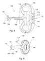
Fig. 1 shows a transmission assembly 10 which is
coupled to an engine (not shown) via an input shaft 12
from the engine. The input shaft 12 is connected to a
planetary gear carrier 15 which has a plurality of
planetary gears 14 mounted thereon, as best shown in
Figs 7a and 7b. The planetary gears 14 are
independently and rotatably mounted on the planetary
gear carrier 15.
A driving member or impeller 16 is coupled to sun gear
18 of the gear train and a driven member or runner 20
is coupled at a first end to ring gear 22. The runner
20 is coupled at a second end to output shaft 24 which
in turn drives the wheels of the vehicle.
The use of planetary gears is common in the automobile
industry, and a detailed description of the function of
such will be omitted.
The first embodiment of the assembly includes a
hydraulic portion (the fluid coupling) and a mechanical
portion (the planetary gear train).
In operation, the input shaft 12 is rotated by the
engine which in turn drives the planetary gear carrier
15 of the gear train. The planetary gears 14 rotate
due to the rotation of the planetary gear carrier 15 of
the gear train assembly and cause rotation of the
impeller 16.
The fluid coupling works on the principle that acting
oil is thrown out from the blades of the impeller 16.
If the flow of acting oil is restricted, then a very
small proportion of oil will be directed towards the
blades of the runner 20 and hence the speed of the
runner 20 and the ring gear 22 should be about zero.
However, due to the engagement of the planetary gears
14 and the ring gear 22, the ring gear 22 will rotate
at a slow speed, with the planet gears 14 taking up the
slip as the sun gear 18 rotates at a much higher speed.
The flow of acting oil is controlled by the position of
a flow control valve 28. In Fig. 1, the valve 28 is
shown in the closed position. With the valve 28
closed, the flow of oil in the torque convertor is
restricted. In these conditions, the impeller 16 will
rotate at a speed which is between 3 and 4 times the
speed of the engine input shaft 12, as there will be a
reduced quantity of oil to be pumped by the impeller
16.
The planetary gears are used to permit the impeller 16
to rotate at a higher speed with respect to the runner
20. As the flow of acting oil is reduced and the
impeller 16 is rotating at this higher speed, full
input torque is transmitted to the output shaft 24.
Gradual opening of the valve 28 will allow acting oil
to circulate in the torque convertor. As the flow of
oil between the impeller 16 and the runner 20 increase,
the speed of the impeller 16 will consequently
decrease. The reduction in speed of the impeller 16 is
due to the increased flow of acting oil towards the
runner 20. Hence, the speed of the runner 20 will
gradually begin to increase as the speed of the
impeller 16 decreases.
In effect, the rotational speed of the impeller 16 is
being lost to the runner 20 until the speed of the
runner 20 approximately matches the speed of the
impeller 16. This will occur when the valve 28 is fully
open as shown in Fig, 3. The speed of the runner 20
cannot be exactly that of the impeller 16 due to slip.
The position of the valve 28 is controlled using a
bracket 30, which is coupled to a shaft 32 of the valve
28 using, for example, a thrust bearing (not shown).
The thrust bearing permits the valve 28 to rotate in
synchronisation with the impeller 16 whilst allowing
the bracket 30 to remain stationary.
To close the valve 28, a hydraulic piston for example
could be coupled to the bracket 30 and the piston
actuated to effect movement of the valve 28. The
travel of the piston should be in the order of 50 to
100 mm.
Gradual retraction of the piston will open the valve
28, thereby increasing the flow of acting oil within
the torque convertor and engaging the transmission.
The valve 28 is provided with a plurality of slots 32.
The slots 32 allow the vanes of the impeller 16 to
slide within these slots, thereby closing the valve 28
as shown in Fig. 1.
It will be appreciated that there are many alternatives
to the use of a piston, such as a pulley or a lever.
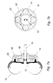
Turning now to Figs 5 and 6 there is shown an
alternative transmission assembly 100. Wherever
possible, similar features to the previous embodiment
have been labelled using the same reference numbers
prefixed with a 1.
In this embodiment, a reactor 134 is positioned between
the impeller 116 and the runner 120. The reactor 134
is provided with a plurality of blades 136 which are
rotatable as shown by the arrows 138.
The shaft 140 of the reactor 134 is provided with a
telescopic portion 142 which slides within the shaft
140.
In operation, to restrict the flow of oil between the
impeller 116 and the runner 120, the blades 136 of the
wheel 134 will be turned to prevent passage of oil. In
this shut-off position, the telescopic portion 142 of
the shaft 140 moves towards the blades in the direction
of arrow 144c. The telescopic portion 142 acts against
a plurality of control gears 146 which are coupled to
the blades 136, thereby controlling the position of the
blades 136.
Gradual retraction of the telescopic portion in the
direction of arrow 144o, changes the angle of the
blades and opens then to an in-line position. When the
telescopic portion 142 is fully retracted, the blades
136 will be fully open and allow the maximum quantity
of oil to circulate between the impeller 116 and the
runner 120.
The over-all operation of the transmission assembly 100
is the same as that for the previous embodiment and
hence a detailed description will be omitted. The only
difference in the assembly 100 is the use of the
moveable blades 136 to control the oil flow as opposed
to the use of the valve 28 in the previous embodiment.
Hence, there is provided a transmission assembly which
is variable in terms of speed. By controlling the flow
and the velocity of the acting oil within the
transmission assembly, the transmission of torque
between the impeller (which is coupled to the engine)
and the runner (which is coupled to the drive shaft) is
variable along a large scale. This provides a smooth
power transfer.
Modifications and improvements may be made to the
foregoing without departing from the scope of the
present invention.