EP0832373B1 - Anschlagpuffer, insbesondere querpuffer - Google Patents
Anschlagpuffer, insbesondere querpuffer Download PDFInfo
- Publication number
- EP0832373B1 EP0832373B1 EP96915964A EP96915964A EP0832373B1 EP 0832373 B1 EP0832373 B1 EP 0832373B1 EP 96915964 A EP96915964 A EP 96915964A EP 96915964 A EP96915964 A EP 96915964A EP 0832373 B1 EP0832373 B1 EP 0832373B1
- Authority
- EP
- European Patent Office
- Prior art keywords
- height
- cavity
- sidepart
- stop buffer
- buffer
- Prior art date
- Legal status (The legal status is an assumption and is not a legal conclusion. Google has not performed a legal analysis and makes no representation as to the accuracy of the status listed.)
- Expired - Lifetime
Links
- 239000000872 buffer Substances 0.000 title claims abstract description 35
- 239000004033 plastic Substances 0.000 claims description 6
- 229920003023 plastic Polymers 0.000 claims description 6
- 239000002184 metal Substances 0.000 claims description 2
- 239000000126 substance Substances 0.000 abstract 1
- 230000000750 progressive effect Effects 0.000 description 6
- 230000007704 transition Effects 0.000 description 4
- 238000010586 diagram Methods 0.000 description 2
- 239000000463 material Substances 0.000 description 2
- 238000000034 method Methods 0.000 description 2
- 239000004721 Polyphenylene oxide Substances 0.000 description 1
- 239000004732 Vestoran Substances 0.000 description 1
- 238000005096 rolling process Methods 0.000 description 1
Images

Classifications
-
- F—MECHANICAL ENGINEERING; LIGHTING; HEATING; WEAPONS; BLASTING
- F16—ENGINEERING ELEMENTS AND UNITS; GENERAL MEASURES FOR PRODUCING AND MAINTAINING EFFECTIVE FUNCTIONING OF MACHINES OR INSTALLATIONS; THERMAL INSULATION IN GENERAL
- F16F—SPRINGS; SHOCK-ABSORBERS; MEANS FOR DAMPING VIBRATION
- F16F1/00—Springs
- F16F1/36—Springs made of rubber or other material having high internal friction, e.g. thermoplastic elastomers
- F16F1/373—Springs made of rubber or other material having high internal friction, e.g. thermoplastic elastomers characterised by having a particular shape
-
- B—PERFORMING OPERATIONS; TRANSPORTING
- B61—RAILWAYS
- B61F—RAIL VEHICLE SUSPENSIONS, e.g. UNDERFRAMES, BOGIES OR ARRANGEMENTS OF WHEEL AXLES; RAIL VEHICLES FOR USE ON TRACKS OF DIFFERENT WIDTH; PREVENTING DERAILING OF RAIL VEHICLES; WHEEL GUARDS, OBSTRUCTION REMOVERS OR THE LIKE FOR RAIL VEHICLES
- B61F5/00—Constructional details of bogies; Connections between bogies and vehicle underframes; Arrangements or devices for adjusting or allowing self-adjustment of wheel axles or bogies when rounding curves
- B61F5/02—Arrangements permitting limited transverse relative movements between vehicle underframe or bolster and bogie; Connections between underframes and bogies
- B61F5/04—Bolster supports or mountings
- B61F5/12—Bolster supports or mountings incorporating dampers
- B61F5/125—Bolster supports or mountings incorporating dampers with rubber elements
-
- F—MECHANICAL ENGINEERING; LIGHTING; HEATING; WEAPONS; BLASTING
- F16—ENGINEERING ELEMENTS AND UNITS; GENERAL MEASURES FOR PRODUCING AND MAINTAINING EFFECTIVE FUNCTIONING OF MACHINES OR INSTALLATIONS; THERMAL INSULATION IN GENERAL
- F16F—SPRINGS; SHOCK-ABSORBERS; MEANS FOR DAMPING VIBRATION
- F16F1/00—Springs
- F16F1/36—Springs made of rubber or other material having high internal friction, e.g. thermoplastic elastomers
- F16F1/42—Springs made of rubber or other material having high internal friction, e.g. thermoplastic elastomers characterised by the mode of stressing
- F16F1/422—Springs made of rubber or other material having high internal friction, e.g. thermoplastic elastomers characterised by the mode of stressing the stressing resulting in flexion of the spring
-
- F—MECHANICAL ENGINEERING; LIGHTING; HEATING; WEAPONS; BLASTING
- F16—ENGINEERING ELEMENTS AND UNITS; GENERAL MEASURES FOR PRODUCING AND MAINTAINING EFFECTIVE FUNCTIONING OF MACHINES OR INSTALLATIONS; THERMAL INSULATION IN GENERAL
- F16F—SPRINGS; SHOCK-ABSORBERS; MEANS FOR DAMPING VIBRATION
- F16F1/00—Springs
- F16F1/36—Springs made of rubber or other material having high internal friction, e.g. thermoplastic elastomers
- F16F1/42—Springs made of rubber or other material having high internal friction, e.g. thermoplastic elastomers characterised by the mode of stressing
- F16F1/44—Springs made of rubber or other material having high internal friction, e.g. thermoplastic elastomers characterised by the mode of stressing loaded mainly in compression
-
- F—MECHANICAL ENGINEERING; LIGHTING; HEATING; WEAPONS; BLASTING
- F16—ENGINEERING ELEMENTS AND UNITS; GENERAL MEASURES FOR PRODUCING AND MAINTAINING EFFECTIVE FUNCTIONING OF MACHINES OR INSTALLATIONS; THERMAL INSULATION IN GENERAL
- F16F—SPRINGS; SHOCK-ABSORBERS; MEANS FOR DAMPING VIBRATION
- F16F2236/00—Mode of stressing of basic spring or damper elements or devices incorporating such elements
- F16F2236/02—Mode of stressing of basic spring or damper elements or devices incorporating such elements the stressing resulting in flexion of the spring
-
- F—MECHANICAL ENGINEERING; LIGHTING; HEATING; WEAPONS; BLASTING
- F16—ENGINEERING ELEMENTS AND UNITS; GENERAL MEASURES FOR PRODUCING AND MAINTAINING EFFECTIVE FUNCTIONING OF MACHINES OR INSTALLATIONS; THERMAL INSULATION IN GENERAL
- F16F—SPRINGS; SHOCK-ABSORBERS; MEANS FOR DAMPING VIBRATION
- F16F2236/00—Mode of stressing of basic spring or damper elements or devices incorporating such elements
- F16F2236/04—Compression
Definitions
- This invention relates to a stop buffer, in particular a transverse buffer, in turn for bogies of air-sprung rail vehicles, comprising a rotationally symmetrical body made of rubber or rubber-like plastic, again consisting of a substructure, of which the force F in the direction of action, which corresponds to the axial direction of the rotationally symmetrical body a cavity extends into the body, and from a superstructure with the total height H, which is framed by a substantially flat end face and an outer contour, the outer contour being designed such that a reduction in diameter of the superstructure occurs towards the end face; also a fastening system made of metal or heavy-duty plastic (eg plastic based on PPE; trademark "Vestoran” from Hüls), which in turn consists of a fastening flange and a contact part that is vulcanized onto the body and is arranged inside the side area of the substructure, wherein the axial extent of the contact part determines the axial extent of the substructure; and a stop surface in the area of which
- the outer contour of the superstructure is designed in a stepped manner, namely to form an upper side part with the height H 1 and a rise angle ⁇ and a lower side part with the height H 2 and a rise angle ⁇ , the angle ⁇ being greater than the angle ⁇ , in each case in relation to the direction of action of the force F.
- the inner contour of the cavity is designed such that a maximum cavity height H 3 is produced at an angle of rise ⁇ , specifically with respect to the stop face.
- Such bumpers are known from GB-A-586 608.
- the characteristic curve of a Such cross buffers should ideally consist of the longest possible linear Characteristic curve with a low spring stiffness and a strongly progressive Assemble the characteristic curve.
- the transition area of the two characteristic curves should be as possible be designed small, with a kink in the characteristic curve would be optimal.
- the cross buffer should be large Allow deflections with very small heights.
- a long, linear characteristic curve with A low spring stiffness is desirable in order to prevent initial forces from occurring take longer deflection path without the cross stop larger negative Has an impact on the comfort of the rail vehicle.
- the progressive The characteristic curve is required to absorb the maximum forces that occur.
- Rubber is an elastic, incompressible material. When deforming a print buffer can the displaced rubber volume only on the outer contours delimiting the buffer dodge, which results in an increase in the effective area.
- the rigidity of a print buffer is, among other things, a function of the effective area. With an increase in the effective area, the increases Stiffness of the pressure buffer. A print buffer therefore has a natural progressive Characteristic curve.
- the generic stop buffer is characterized in that the height H 3 is less than the height H 1 of the upper side part.
- the fastening system can be asymmetrical, particularly in the flange area be constructed.
- the cross buffer acts like a pressure-thrust element connected in series.
- An element loaded with shear has an element loaded with pressure Element has a much lower stiffness and generally has no progressive Characteristic curve on.
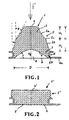
- the cross buffer according to FIG. 2 is deflected, the Superstructure (3) of the rubber body (1, 1 ') moved into the cavity below, whereby creates the outer contour (5) of the buffer on the contact surface (4).
- This process is continuous Enlargement of the contact area (4 ') as a result (Fig. 2), which, however, has no major influence has the buffer characteristic.
- the buffer characteristic is determined by the shear rigidity of the in the plane of the Cavity remaining rubber cross section determined.
- the inventive design of the cross buffer makes a long linear one Characteristic curve with low rigidity realized.
- the inner contour (9) of the cavity (8) within the substructure (2) is designed so that the Rubber contour only when the desired transition point from the linear to the progressive area of the characteristic, suddenly and with the entire contact surface (9 ') at the same time, comes into contact with the stop surface (7) (Fig. 2).
- the contact is made without prior Rolling contacts that cause the transition area of the two to blur Characteristic curves would lead.
- the rubber contour of the superstructure (3) is selected in this way that the process of not adding stiffness to the outer contour (5) exactly to the The point at which the characteristic curve transition is completed is at which the rubber contour in the cavity comes into contact with the stop surface (7) (Fig. 2).
- the outer contour (5 ') lies at this time exactly up to the height-defined paragraph (5c) that is matched to the deflection, over the entire surface of the upper contact surface (4 ') (Fig. 2). The result is a leap Increase in stiffness.
- FIG. 3 shows the characteristic curve curve described above, namely under the Point of view of the path L in mm (abscissa) depending on the force F in KN (ordinate).
Landscapes
- Engineering & Computer Science (AREA)
- General Engineering & Computer Science (AREA)
- Mechanical Engineering (AREA)
- Health & Medical Sciences (AREA)
- Child & Adolescent Psychology (AREA)
- Vibration Prevention Devices (AREA)
- Vibration Dampers (AREA)
- Bridges Or Land Bridges (AREA)
Description
- H1 = (0,3 bis 0,7) x H
H2 = (0,7 bis 0,3) x H - α = 0 bis 30°, insbesondere 5 bis 30°
β =10 bis 55°
γ =10 bis 50°
- 1
- Gummikörper
- 1'
- Gummikörper
- 2
- Unterbau
- 3
- Oberbau mit der Gesamthöhe H
- 4
- Stirnfläche (Kontaktfläche)
- 4'
- Stirnfläche (Kontaktfläche)
- 5
- Außenkontur
- 5a
- oberes Seitenteil mit der Höhe H1 und dem Anstiegswinkel β
- 5b
- unteres Seitenteil mit der Höhe H2 und dem Anstiegswinkel α
- 5c
- Absatz
- 5
- Außenkontur
- 6
- Befestigungssystem
- 6a
- Flansch
- 6b
- Kontaktteil zum Gummikörper
- 7
- Anschlagfläche
- 8
- Hohlraum in Wirkungsrichtung der Kraft F mit maximaler Höhe H3
- 9
- Innenkontur mit Anstiegswinkel γ
- 9'
- Auflagefläche (Innenkontur im belasteten Zustand)
Claims (8)
- Anschlagpuffer insbesondere Querpuffer, insbesondere wiederum für Drehgestelle von luftgefederten Schienenfahrzeugen, umfassendeinen rotationssymmetrischen Körper (1) aus Gummi oder gummiähnlichem Kunststoff, bestehend wiederum auseinem Unterbau (2), von dem in Wirkungsrichtung der Kraft F, die der axialen Richtung des rotationssymmetrischen Körpers (1) entspricht, sich ein Hohlraum (8) in den Körper (1) hinein erstreckt, sowie auseinem Oberbau (3) mit der Gesamthöhe H, der von einer im wesentlichen ebenflächigen Stirnfläche (4) sowie einer Außenkontur (5) umrahmt ist, wobei die Außenkontur so gestaltet ist, daß zur Stirnfiäche hin eine Durchmesserverringerung des Oberbaus auftritt; fernerein Befestigungssystem (6) aus Metall oder hochbelastbarem Kunststoff, bestehend wiederum aus einem Befestigungsflansch (6a) und einem Kontaktteil (6b), das an dem Körper anvulkanisiert ist und dabei innerhalb des Seitenbereiches des Unterbaues (2) angeordnet ist, wobei die axiale Erstreckung des Kontaktteiles (6b) die axiale Erstreckung des Unterbaues (2) bestimmt; sowieeine Anschlagfläche (7), in deren Bereich der Hohlraum (8) des Körpers seinen größten Durchmesser D besitzt; wobeidie Außenkontur (5) des Oberbaues abgestuft gestaltet ist (5c), und zwar unter Bildung eines oberen Seitenteiles (5a) mit der Höhe H1 und einem Anstiegswinkel β sowie eines unteren Seitenteiles (5b) mit der Höhe H2 und einem Anstiegswinkel α, wobei der Winkel β größer ist als der Winkel α, und zwar jeweils bezogen auf die Wirkungsrichtung der Kraft F; wobei fernerdadurch gekennzeichnet, daßdie Innenkontur (9) des Hohlraumes (8) so ausgelegt ist, daß bei einem Anstiegswinkel γ, und zwar bezogen auf die Anschlagfläche (7), eine maximale Hohlraumhöhe H3 entsteht;die Höhe H3 kleiner ist als die Höhe H1 des oberen Seitenteiles (5a).
- Anschlagpuffer nach Anspruch 1, dadurch gekennzeichnet, daß für die Höhe H1 des oberen Seitenteiles (5a) und die Höhe H2 des unteren Seitenteiles (5b) folgende Parameter gelten:
- Anschlagpuffer nach Anspruch 1 oder 2, dadurch gekennzeichnet, daß der Winkel α des unteren Seitenteiles (5b) 0 bis 30°, insbesondere 5 bis 30°, beträgt.
- Anschlagpuffer nach einem der Ansprüche 1 bis 3, dadurch gekennzeichnet, daß der Winkel β des oberen Seitenteiles (5a) 10 bis 55° beträgt.
- Anschlagpuffer nach einem der Ansprüche 1 bis 4, dadurch gekennzeichnet, daß der Winkel γ des Hohlraumes (8) 10 bis 50° beträgt.
- Anschlagpuffer nach einem der Ansprüche 1 bis 5, dadurch gekennzeichnet, daß die Außenkontur der Seitenteile (5a, 5b), insbesondere die Außenkontur des oberen Seitenteiles (5a), konkav ausgebildet ist.
- Anschlagpuffer nach einem der Ansprüche 1 bis 6, dadurch gekennzeichnet, daß die Innenkontur (9) des Hohlraumes (8) im Bereich der maximalen Hohlraumhöhe H3 konkav ausgebildet ist.
- Anschlagpuffer nach einem der Ansprüche 1 bis 7, dadurch gekennzeichnet, daß sich der Hohlraum (8) im wesentlichen über die gesamte Anschlagfläche (7) erstreckt.
Applications Claiming Priority (3)
| Application Number | Priority Date | Filing Date | Title |
|---|---|---|---|
| DE19520716 | 1995-06-12 | ||
| DE19520716 | 1995-06-12 | ||
| PCT/DE1996/000974 WO1996041971A1 (de) | 1995-06-12 | 1996-06-04 | Anschlagpuffer, insbesondere querpuffer |
Publications (2)
| Publication Number | Publication Date |
|---|---|
| EP0832373A1 EP0832373A1 (de) | 1998-04-01 |
| EP0832373B1 true EP0832373B1 (de) | 1999-01-27 |
Family
ID=7763791
Family Applications (1)
| Application Number | Title | Priority Date | Filing Date |
|---|---|---|---|
| EP96915964A Expired - Lifetime EP0832373B1 (de) | 1995-06-12 | 1996-06-04 | Anschlagpuffer, insbesondere querpuffer |
Country Status (5)
| Country | Link |
|---|---|
| EP (1) | EP0832373B1 (de) |
| AT (1) | ATE176304T1 (de) |
| DE (2) | DE19622243A1 (de) |
| ES (1) | ES2128860T3 (de) |
| WO (1) | WO1996041971A1 (de) |
Cited By (1)
| Publication number | Priority date | Publication date | Assignee | Title |
|---|---|---|---|---|
| CN106364515A (zh) * | 2016-08-29 | 2017-02-01 | 中车大连机车车辆有限公司 | 机车转向架用横向止挡及其设计方法 |
Families Citing this family (4)
| Publication number | Priority date | Publication date | Assignee | Title |
|---|---|---|---|---|
| CN106476835B (zh) * | 2015-08-28 | 2018-10-19 | 株洲时代新材料科技股份有限公司 | 一种带磨耗板的垂向止挡及防止钢弹簧断裂的方法 |
| CN107264558A (zh) * | 2016-04-06 | 2017-10-20 | 中车长春轨道客车股份有限公司 | 一种止挡及具有该止挡的转向架 |
| CN113642113B (zh) * | 2021-08-26 | 2023-10-03 | 株洲时代瑞唯减振装备有限公司 | 横向止挡的设计方法 |
| CN116750029A (zh) * | 2023-08-04 | 2023-09-15 | 株洲时代瑞唯减振装备有限公司 | 一种横向止档 |
Family Cites Families (5)
| Publication number | Priority date | Publication date | Assignee | Title |
|---|---|---|---|---|
| GB586608A (en) * | 1944-08-21 | 1947-03-25 | James William La French Norman | Improvements in and relating to resilient mountings for machinery, instruments and the like |
| DE1908844U (de) * | 1963-03-11 | 1965-01-21 | Lemfoerder Metallwarengesellsc | Druckbeanspruchter ungefuehrter federungskoerper aus elastischem werkstoff, vorzugsweise einem solchen mit zellstruktur. |
| DE1242057B (de) * | 1964-07-03 | 1967-06-08 | Continental Gummi Werke Ag | Gummifeder |
| DE2856200A1 (de) * | 1977-12-27 | 1979-07-05 | Sumitomo Rubber Ind | Fender oder prellvorrichtung |
| JPS5878812A (ja) * | 1981-11-05 | 1983-05-12 | Nissan Motor Co Ltd | 車体とサスペンシヨンとの間に配設される圧縮弾性体 |
-
1996
- 1996-06-04 AT AT96915964T patent/ATE176304T1/de active
- 1996-06-04 ES ES96915964T patent/ES2128860T3/es not_active Expired - Lifetime
- 1996-06-04 DE DE19622243A patent/DE19622243A1/de not_active Withdrawn
- 1996-06-04 EP EP96915964A patent/EP0832373B1/de not_active Expired - Lifetime
- 1996-06-04 DE DE59601236T patent/DE59601236D1/de not_active Expired - Lifetime
- 1996-06-04 WO PCT/DE1996/000974 patent/WO1996041971A1/de not_active Ceased
Cited By (1)
| Publication number | Priority date | Publication date | Assignee | Title |
|---|---|---|---|---|
| CN106364515A (zh) * | 2016-08-29 | 2017-02-01 | 中车大连机车车辆有限公司 | 机车转向架用横向止挡及其设计方法 |
Also Published As
| Publication number | Publication date |
|---|---|
| DE19622243A1 (de) | 1996-12-19 |
| EP0832373A1 (de) | 1998-04-01 |
| ATE176304T1 (de) | 1999-02-15 |
| ES2128860T3 (es) | 1999-05-16 |
| WO1996041971A1 (de) | 1996-12-27 |
| DE59601236D1 (de) | 1999-03-11 |
Similar Documents
| Publication | Publication Date | Title |
|---|---|---|
| DE3788285T2 (de) | Elastisches lasttragendes und schwingungsanpassungsfähiges lager. | |
| DE2726676C2 (de) | Federelement zur elastischen Lagerung von Antriebs- oder sonstigen Aggregaten | |
| DE3525213A1 (de) | Elastische buchse | |
| DE10007789A1 (de) | Stossdämpfender Anschlag | |
| DE1805219A1 (de) | Federung fuer Fahrzeuge,insbesondere Kraftfahrzeuge | |
| DE19907783A1 (de) | Schutzvorrichtung für Kraftfahrzeuge | |
| DE102020114849A1 (de) | Schalldämpfer für blattfeder für nutzfahrzeug | |
| DE7141159U (de) | Elastisches Lager, insbesondere für Achsbefestigungen und Achsführungselemente an Kraftfahrzeugen | |
| EP0229940B1 (de) | Elastisches Lager für die Lagerung des Fahrerhauses eines Lastkraftwagens | |
| DE1931940A1 (de) | Elastisches Motorlager | |
| DE1933149B2 (de) | Verformbares Tragwerk eines Kraft fahrzeuges und Verfahren zu seiner Her stellung | |
| EP0832373A1 (de) | Anschlagpuffer, insbesondere querpuffer | |
| DE2826923A1 (de) | Elastisches motorlager, insbesondere fuer kraftfahrzeuge | |
| DE29610365U1 (de) | Anschlagpuffer, insbesondere Querpuffer | |
| EP3682134A1 (de) | Anfahrpuffer | |
| DE102009000510B4 (de) | Molekulargelenk, insbesondere zur Verwendung in Kraftfahrzeugen | |
| EP1352802B1 (de) | Mittelpufferkupplungsanordnung | |
| DE3342502C2 (de) | ||
| DE2941274A1 (de) | Elastische halterung | |
| DE3432768C2 (de) | ||
| DE3519868A1 (de) | Elastisches lager fuer die lagerung des fahrerhauses eines lastkraftwagens | |
| DE69508544T2 (de) | Energieabsorbierender Balken und dünnes metallisches Blech zu dessen Realisierung | |
| DE19601120C1 (de) | Gleitbacken | |
| DE3008168A1 (de) | Elastische lager, insbesondere fuer den antriebsmotor in kraftfahrzeugen | |
| DE202020107166U1 (de) | Fahrzeugsitz-Unterbau |
Legal Events
| Date | Code | Title | Description |
|---|---|---|---|
| PUAI | Public reference made under article 153(3) epc to a published international application that has entered the european phase |
Free format text: ORIGINAL CODE: 0009012 |
|
| 17P | Request for examination filed |
Effective date: 19971002 |
|
| AK | Designated contracting states |
Kind code of ref document: A1 Designated state(s): AT BE CH DE DK ES FI FR GB GR IE IT LI LU NL PT SE |
|
| GBC | Gb: translation of claims filed (gb section 78(7)/1977) | ||
| GRAG | Despatch of communication of intention to grant |
Free format text: ORIGINAL CODE: EPIDOS AGRA |
|
| GRAG | Despatch of communication of intention to grant |
Free format text: ORIGINAL CODE: EPIDOS AGRA |
|
| GRAH | Despatch of communication of intention to grant a patent |
Free format text: ORIGINAL CODE: EPIDOS IGRA |
|
| 17Q | First examination report despatched |
Effective date: 19981009 |
|
| GRAH | Despatch of communication of intention to grant a patent |
Free format text: ORIGINAL CODE: EPIDOS IGRA |
|
| GRAA | (expected) grant |
Free format text: ORIGINAL CODE: 0009210 |
|
| AK | Designated contracting states |
Kind code of ref document: B1 Designated state(s): AT BE CH DE DK ES FI FR GB GR IE IT LI LU NL PT SE |
|
| PG25 | Lapsed in a contracting state [announced via postgrant information from national office to epo] |
Ref country code: GR Free format text: LAPSE BECAUSE OF NON-PAYMENT OF DUE FEES Effective date: 19990127 Ref country code: FI Free format text: LAPSE BECAUSE OF NON-PAYMENT OF DUE FEES Effective date: 19990127 |
|
| REF | Corresponds to: |
Ref document number: 176304 Country of ref document: AT Date of ref document: 19990215 Kind code of ref document: T |
|
| REG | Reference to a national code |
Ref country code: CH Ref legal event code: EP |
|
| REG | Reference to a national code |
Ref country code: CH Ref legal event code: NV Representative=s name: E. BLUM & CO. PATENTANWAELTE |
|
| REG | Reference to a national code |
Ref country code: IE Ref legal event code: FG4D Free format text: GERMAN |
|
| REF | Corresponds to: |
Ref document number: 59601236 Country of ref document: DE Date of ref document: 19990311 |
|
| ET | Fr: translation filed | ||
| PG25 | Lapsed in a contracting state [announced via postgrant information from national office to epo] |
Ref country code: PT Free format text: LAPSE BECAUSE OF FAILURE TO SUBMIT A TRANSLATION OF THE DESCRIPTION OR TO PAY THE FEE WITHIN THE PRESCRIBED TIME-LIMIT Effective date: 19990427 Ref country code: DK Free format text: LAPSE BECAUSE OF FAILURE TO SUBMIT A TRANSLATION OF THE DESCRIPTION OR TO PAY THE FEE WITHIN THE PRESCRIBED TIME-LIMIT Effective date: 19990427 |
|
| REG | Reference to a national code |
Ref country code: ES Ref legal event code: FG2A Ref document number: 2128860 Country of ref document: ES Kind code of ref document: T3 |
|
| GBT | Gb: translation of ep patent filed (gb section 77(6)(a)/1977) |
Effective date: 19990422 |
|
| PG25 | Lapsed in a contracting state [announced via postgrant information from national office to epo] |
Ref country code: LU Free format text: LAPSE BECAUSE OF NON-PAYMENT OF DUE FEES Effective date: 19990604 |
|
| PG25 | Lapsed in a contracting state [announced via postgrant information from national office to epo] |
Ref country code: IE Free format text: LAPSE BECAUSE OF NON-PAYMENT OF DUE FEES Effective date: 19990820 |
|
| REG | Reference to a national code |
Ref country code: IE Ref legal event code: FD4D |
|
| PLBE | No opposition filed within time limit |
Free format text: ORIGINAL CODE: 0009261 |
|
| STAA | Information on the status of an ep patent application or granted ep patent |
Free format text: STATUS: NO OPPOSITION FILED WITHIN TIME LIMIT |
|
| 26N | No opposition filed | ||
| REG | Reference to a national code |
Ref country code: GB Ref legal event code: IF02 |
|
| REG | Reference to a national code |
Ref country code: CH Ref legal event code: PFA Owner name: PHOENIX AKTIENGESELLSCHAFT Free format text: PHOENIX AKTIENGESELLSCHAFT#HANNOVERSCHE STRASSE 88#21079 HAMBURG (DE) -TRANSFER TO- PHOENIX AKTIENGESELLSCHAFT#HANNOVERSCHE STRASSE 88#21079 HAMBURG (DE) |
|
| PGFP | Annual fee paid to national office [announced via postgrant information from national office to epo] |
Ref country code: ES Payment date: 20120627 Year of fee payment: 17 |
|
| PGFP | Annual fee paid to national office [announced via postgrant information from national office to epo] |
Ref country code: AT Payment date: 20120613 Year of fee payment: 17 |
|
| PGFP | Annual fee paid to national office [announced via postgrant information from national office to epo] |
Ref country code: CH Payment date: 20130621 Year of fee payment: 18 Ref country code: GB Payment date: 20130619 Year of fee payment: 18 Ref country code: DE Payment date: 20130630 Year of fee payment: 18 Ref country code: SE Payment date: 20130619 Year of fee payment: 18 |
|
| PGFP | Annual fee paid to national office [announced via postgrant information from national office to epo] |
Ref country code: NL Payment date: 20130619 Year of fee payment: 18 Ref country code: IT Payment date: 20130625 Year of fee payment: 18 Ref country code: FR Payment date: 20130703 Year of fee payment: 18 |
|
| PGFP | Annual fee paid to national office [announced via postgrant information from national office to epo] |
Ref country code: BE Payment date: 20130619 Year of fee payment: 18 |
|
| REG | Reference to a national code |
Ref country code: DE Ref legal event code: R119 Ref document number: 59601236 Country of ref document: DE |
|
| REG | Reference to a national code |
Ref country code: NL Ref legal event code: V1 Effective date: 20150101 |
|
| PG25 | Lapsed in a contracting state [announced via postgrant information from national office to epo] |
Ref country code: SE Free format text: LAPSE BECAUSE OF NON-PAYMENT OF DUE FEES Effective date: 20140605 |
|
| REG | Reference to a national code |
Ref country code: CH Ref legal event code: PL |
|
| REG | Reference to a national code |
Ref country code: SE Ref legal event code: EUG |
|
| REG | Reference to a national code |
Ref country code: AT Ref legal event code: MM01 Ref document number: 176304 Country of ref document: AT Kind code of ref document: T Effective date: 20140604 |
|
| GBPC | Gb: european patent ceased through non-payment of renewal fee |
Effective date: 20140604 |
|
| REG | Reference to a national code |
Ref country code: FR Ref legal event code: ST Effective date: 20150227 |
|
| PG25 | Lapsed in a contracting state [announced via postgrant information from national office to epo] |
Ref country code: NL Free format text: LAPSE BECAUSE OF NON-PAYMENT OF DUE FEES Effective date: 20150101 |
|
| REG | Reference to a national code |
Ref country code: DE Ref legal event code: R119 Ref document number: 59601236 Country of ref document: DE Effective date: 20150101 |
|
| PG25 | Lapsed in a contracting state [announced via postgrant information from national office to epo] |
Ref country code: CH Free format text: LAPSE BECAUSE OF NON-PAYMENT OF DUE FEES Effective date: 20140630 Ref country code: LI Free format text: LAPSE BECAUSE OF NON-PAYMENT OF DUE FEES Effective date: 20140630 Ref country code: DE Free format text: LAPSE BECAUSE OF NON-PAYMENT OF DUE FEES Effective date: 20150101 Ref country code: IT Free format text: LAPSE BECAUSE OF NON-PAYMENT OF DUE FEES Effective date: 20140604 |
|
| PG25 | Lapsed in a contracting state [announced via postgrant information from national office to epo] |
Ref country code: FR Free format text: LAPSE BECAUSE OF NON-PAYMENT OF DUE FEES Effective date: 20140630 Ref country code: AT Free format text: LAPSE BECAUSE OF NON-PAYMENT OF DUE FEES Effective date: 20140604 Ref country code: GB Free format text: LAPSE BECAUSE OF NON-PAYMENT OF DUE FEES Effective date: 20140604 |
|
| REG | Reference to a national code |
Ref country code: ES Ref legal event code: FD2A Effective date: 20150724 |
|
| PG25 | Lapsed in a contracting state [announced via postgrant information from national office to epo] |
Ref country code: ES Free format text: LAPSE BECAUSE OF NON-PAYMENT OF DUE FEES Effective date: 20140605 |
|
| PG25 | Lapsed in a contracting state [announced via postgrant information from national office to epo] |
Ref country code: BE Free format text: LAPSE BECAUSE OF NON-PAYMENT OF DUE FEES Effective date: 20140630 |