EP0832010B1 - Hebebühne zum befestigen an einer plattform eines lastkraftwagens - Google Patents
Hebebühne zum befestigen an einer plattform eines lastkraftwagens Download PDFInfo
- Publication number
- EP0832010B1 EP0832010B1 EP96918925A EP96918925A EP0832010B1 EP 0832010 B1 EP0832010 B1 EP 0832010B1 EP 96918925 A EP96918925 A EP 96918925A EP 96918925 A EP96918925 A EP 96918925A EP 0832010 B1 EP0832010 B1 EP 0832010B1
- Authority
- EP
- European Patent Office
- Prior art keywords
- slider
- column
- container
- lift device
- side wall
- Prior art date
- Legal status (The legal status is an assumption and is not a legal conclusion. Google has not performed a legal analysis and makes no representation as to the accuracy of the status listed.)
- Expired - Lifetime
Links
- 238000009412 basement excavation Methods 0.000 claims description 8
- 238000007789 sealing Methods 0.000 claims description 8
- 230000004888 barrier function Effects 0.000 claims description 3
- XAGFODPZIPBFFR-UHFFFAOYSA-N aluminium Chemical compound [Al] XAGFODPZIPBFFR-UHFFFAOYSA-N 0.000 claims description 2
- 229910052782 aluminium Inorganic materials 0.000 claims description 2
- 239000004411 aluminium Substances 0.000 claims description 2
- 238000001125 extrusion Methods 0.000 claims description 2
- 210000000614 rib Anatomy 0.000 description 21
- 230000007246 mechanism Effects 0.000 description 6
- 239000000725 suspension Substances 0.000 description 3
- 230000003245 working effect Effects 0.000 description 2
- 235000011483 Ribes Nutrition 0.000 description 1
- 241000220483 Ribes Species 0.000 description 1
- 230000009471 action Effects 0.000 description 1
- 230000005540 biological transmission Effects 0.000 description 1
- 238000010276 construction Methods 0.000 description 1
- 238000005553 drilling Methods 0.000 description 1
- 230000004048 modification Effects 0.000 description 1
- 238000012986 modification Methods 0.000 description 1
- 238000004804 winding Methods 0.000 description 1
Images


Classifications
-
- B—PERFORMING OPERATIONS; TRANSPORTING
- B60—VEHICLES IN GENERAL
- B60P—VEHICLES ADAPTED FOR LOAD TRANSPORTATION OR TO TRANSPORT, TO CARRY, OR TO COMPRISE SPECIAL LOADS OR OBJECTS
- B60P1/00—Vehicles predominantly for transporting loads and modified to facilitate loading, consolidating the load, or unloading
- B60P1/44—Vehicles predominantly for transporting loads and modified to facilitate loading, consolidating the load, or unloading having a loading platform thereon raising the load to the level of the load-transporting element
- B60P1/4414—Vehicles predominantly for transporting loads and modified to facilitate loading, consolidating the load, or unloading having a loading platform thereon raising the load to the level of the load-transporting element and keeping the loading platform parallel to the ground when raising the load
- B60P1/4421—Vehicles predominantly for transporting loads and modified to facilitate loading, consolidating the load, or unloading having a loading platform thereon raising the load to the level of the load-transporting element and keeping the loading platform parallel to the ground when raising the load the loading platform being carried in at least one vertical guide
Definitions
- the invention relates to a loading lift device for mounting to the container of a truck as this is described in the preamble of claim 1.
- Such a device is known from US-A-4 563 121.
- the column is provided with two separate V-shaped guides (32) one of which has to be adjustable in view of the fact that they are provided at a relatively large distance from each other so that tolerances in the dimensions and deviations in these caused by temperature variations have to be taken into account.
- the object of the invention is to remove these disadvantages and to that end the features indicated in the characterizing portion of the main claim are provided.
- the parts for guiding a slider in respect of a column being positioned such that no adjustable parts are necessary, the space in which the means for moving the slider is positioned lying outside the parts for guiding the slider.
- the protuberance is represented by a single rib onto which one or more strips of plastic are fixed, and the excavation is represented by two L-shaped ribs at some distance from each other together comprising the plastic ribs.
- the sliding surfaces between protuberance and excavation and the points of action for the means for moving the sliders in relation to the columns can be substantially in a plane coinciding with, or being parallel to, the side wall of the container. Due to this, an advantageous transmission of the occurring forces is achieved.
- the profile of the slider and that of the column can be achieved by extrusion from aluminium. Then, the profiles need only be subjected to a few further workings. These further workings could be e.g. the drilling of holes for the bolts by which the profiles are secured to the other parts.
- the columns can be secured to the rear edges of the container, for example. They can also be part of the end edge of the container and at their upper ends be connected by a top rail and at their lower ends by a part of the floor structure.
- the profile of the column can be provided with a vertically extending edge portion directed backwards in relation to the container, upon which edge portion a sealing strip can be mounted which can cooperate with the loading platform in its folded upward condition, or with a door or the like mounted to the loading platform.
- the profile of the sliders can extend beyond the edge portion of the column so that a moisture barrier is formed between said edge portion and the loading platform.
- the side walls of the columns are located opposite each other and that the side walls of the sliders are located in the prolongation of the side walls of the container, in which the two vertical spaces for receiving at least one part of the means for moving the sliders in vertical direction are formed between the stiffening or connecting ribs of the side walls of slider and column and a part of the side wall of the column.
- the space concerned can then be open to the outside so that the means for moving the slider are easily accessible.
- Said space can be covered up by a releasable plate being located in the prolongation of the container side wall. Naturally, the space will continue through the container floor so that the sliders can be moved over a considerable height.
- the outer surface of the side walls of the columns can connect to the outer surface of the container side walls and the vertical space for receiving the means for moving the slider in relation to the column can be formed between stiffening ribs of the column and of the slider, said space further being limited by a part of the side wall rib of the slider.
- the column is provided with a second substantially plate-shaped longitudinal rib at least partly enclosing the slider and having its free vertical end edge provided with a sealing strip that can cooperate with the loading platform in its folded-up condition or with a door or the like closing off the container.
- the space for receiving the moving means of a slider can be formed by a prolongation of the stiffening rib of the column being located in the plane of the charging opening, the second longitudinal rib of the column, the side wall of the slider and a stiffening rib connected to it.
- the space for the moving means is located behind the stiffening rib of the column being situated at the greatest distance from the container and between the side wall of the slider and a stiffening rib connected to it.
- the space concerned can be open to the outside and said space can be sealed by a releasable covering plate.
- the means for moving the sliders in relation to the columns can be represented by pressurized medium-operated cylinders being situated in said spaces.
- pressurized medium-operated cylinders being situated in said spaces.
- tie rods or cables are applied, which extend upwards through the spaces and are led across guiding means to a pressurized medium-operated cylinder or to a winding mechanism.
- the loading platform is directly pivotably connected to both sliders, in such a way that both sliders are connected to each other by means of the loading platform.
- Means for securing the loading platform in certain positions will have been provided between the sliders and the loading platform, and the sliders and the loading platform will be executed in such a way that in folded-in condition of the loading platform, the means are completely received within the sliders.
- Said means can be in the form of gas springs, for example. Pressurized medium-operated cylinders can be applied as well.
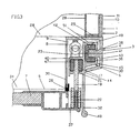
- Figs. 1 shows a part of a vehicle 1 being provided with a container 2 to which a loading lift device 3 is mounted, only part of which being shown.
- the loading lift device comprises the columns 4 connecting to the side walls 10 and along which sliders 6 i are movable for moving the loading platform 7 up and down by means of the hoisting mechanism 8.
- Said hoisting mechanism 8, which can be a pressurized medium-operated cylinder, as indicated in the Figures 1, 3 and 4 or a tie rod or cable is located in the vertical space 9 continuing substantially across the entire height of column 4 and slider 6.
- the hoisting mechanism is in the form of belts or cables, these can be wound onto a drum not further indicated and be led across rollers. In the latter case, they can also be connected to a pressurized medium-operated cylinder.
- the outer surface of the slider 6 can be in the same plane 31 as the outer surface of the side wall 10 of the container 2.
- the space 9 could be closed off by a part of the slider 6, it is preferably provided for, that the space is kept accessible and that it can be closed off by a releasable covering plate 27.
- the side wall 43 of the column 4 can have a sliding member 38 comprising a protuberance 42 cooperating with an excavation 49 formed by two ribs 45 wich can act as stiffening ribes for the side wall 44 of the slider 6 at the same time.
- the plane in which the parts are movable in relation to each other is indicated by 41.
- the side wall 44 of the slider 6 is further provided with a stiffening rib 40 also carrying the pivot for the loading platform 7.
- the slider 6 provided with the excavation 49 cooperates with the sliding member 38 provided to the side wall 43 of the column 4.
- the ribs 45 are provided with the parts 36 enclosing the protuberance 42 of the sliding member 38, said protuberance 42 consisting of a U-shaped strip 13 of plastic that has been secured on the part connected to the column 4.
- the column 4 is further provided with stiffening ribs 51 so that the column can be fixed to the connecting beam 25 between the outer wall 11 and the inner wall 29 of the side wall 10 of the container by means of bolts 46.
- sliding member 38 integrally from one single plastic strip being secured on the side wall 43 of the column 4.
- the slider 6 has a space 17 being defined by a substantially L-shaped stiffening rib 40.
- the space 17 contains the closing mechanism 47 being connected to the sliding part 19 protruding outwards through the slot 21 and being provided with the pivot for loading platform 7.
- the loading platform 7 is further connected to a suspension member 20. Due to this, the loading platform 7 can be locked in certain positions.
- the suspension member 20 is represented by a pressurized medium-operated cylinder.
- the side wall 43 of the column 4 has an extension 30 at its end edge being provided with the sealing strip 26 to which the loading platform 7 connects in its closed position.
- the charging opening is defined by the loading floor 28 or its extension 34, by the sealing strips 26 and the roof of the container 2.
- the extension 30 can additionally be provided with a stiffening rib.
- the side wall 44 of the slider 6 is provided with an extension 32 for laterally defining the space within which the loading platform 7 is located when in the closed position.
- the extension 32 is provided with a stiffening rib 48.
- the cylinder of a pressurized medium-operated cylinder 8 can be connected to the column 4, the piston rod of said cylinder being connected to the slider 6 by fastening means 23 mounted to it.
- the cylinder 8 is located in the vertical space 9 extending downwards through or along the floor 28 of the container 2.
- Fig. 2 shows a side view and partial cross-section across a portion of the device, to wit in particular: the loading floor 28, its extension 34, extending between the columns 4, the sliders 6, the loading platform 7 fastened to the sliders, its suspension member 20, and the space 9 in which the hoisting mechanism 8, such as in the form of a pressurized medium-operated cylinder, is situated.
- the loading platform 7 is located in a lower position, such as close to the ground, so that a load can be placed on it or be removed from it. Further the loading platform 7 can be brought into the closed position so that it closes off the opening 5 of the container 2.
- Fig. 3 shows a cross-section corresponding to Fig. 1, but of a slightly modified embodiment. Corresponding parts have been indicated with the same reference numbers.
- the outer surface of the side wall 43 of the column 4 is situated in the plane 31 in which the outer surface 31 of the side wall 10 of the container 2 is situated as well.
- the part 30 of the side wall 43 carrying the sealing strip 26 now encloses the slider 6.
- the slider 6 is again slidably connected to the column 4 in the same way as in the previously described embodiment.
- the space 9 in which the pressurized medium-operated cylinder 8 is situated is now completely closed off, naturally with the exception of its lower end.
- Fig. 4 largely corresponds to the one according to Fig. 3. However, here the space 9, in which the pressurized medium-operated cylinder 8 is situated, is mounted behind the column 4, as seen from the container 2.
- the side wall 43 of the column 4 is provided with a stiffening rib 52 to which the cylinder 8 has been fixed.
- the cylinder 8 is again connected to the slider 6 by the connecting means 23 in the known way. Now, the space 9 is accessible from the outside again and can be closed off by the covering plate 27.
Landscapes
- Engineering & Computer Science (AREA)
- Transportation (AREA)
- Mechanical Engineering (AREA)
- Loading Or Unloading Of Vehicles (AREA)
- Forklifts And Lifting Vehicles (AREA)
- Wing Frames And Configurations (AREA)
- Handcart (AREA)
Claims (10)
- Hubladevorrichtung zum Befestigen an einem Behälter (2) eines Lastkraftwagens (1), wobei besagte Hubladevorrichtung (3), gesehen in ihrem montierten Zustand, zwei vertikale Säulen (4) umfasst, die zu beiden Seiten der Ladeöffnung (5) an dem Behälter (2) befestigt sind oder einen Teil davon darstellen, wobei besagte Säulen (4) mit Mitteln versehen sind, um verschiebbar Schlitten (6) aufzunehmen, an denen eine Ladeplattform (7) scharnierbar befestigt ist, wobei Mittel (8) zum Bewegen der Schlitten vorgesehen sind, wobei besagte Mittel an einer Seite an den Säulen (4) oder dem Behälter (2) und an der anderen Seite an den Schlitten (6) befestigt sind und jeweils in einem von Teilen einer Säule und eines Schlittens gebildeten Raum (9) positioniert sind, wobei jede der besagten Säulen (4) und Schlitten (6) in Form länglicher Träger vorliegt, die sich in vertikaler Richtung erstrecken und eine plattenförmige Längs-Seitenwand (43,44) aufweisen, die, gesehen in Draufsicht, sich in Längsrichtung des Behälters (2) und hauptsächlich parallel zu dessen Seitenwand (10) erstrecken, wobei die Seitenwand (43,44) einerseits, wie entweder die Säule (4) oder der Schlitten (6), mit Vorsprüngen versehen sind, die eine sich in Längsrichtung des Trägers erstreckende Höhlung bilden, dadurch gekennzeichnet, dass die Seitenwände (43,44) sowohl der Säule (4) als auch des Schlittens (6) mit Vorsprüngen (42,38) und Verstärkungsrippen (40,45,51,52) versehen sind, wobei alle besagten Vorsprünge und Rippen hauptsächlich senkrecht zu den Seitenwänden (43,44) entweder der Säule (4) oder des Schlittens (6) verlaufen, wobei besagte Höhlung (49) mit einem Vorsprung (42) auf dem anderen Teil zusammenwirkt, um die Gleitverbindung zwischen beiden Teilen (4,6) herzustellen, wobei besagte Höhlung außerhalb des Raums (9) angeordnet ist, worin die Mittel (8) zum Bewegen des Schlittens (6) positioniert sind, wobei zumindest ein Teil der Seitenwand (44) des Schlittens (6) oder eine Verstärkungsrippe besagter Seitenwand sich zu dessen Bewegungsmitteln hin erstreckt, wobei besagte Seitenwände (43,44) der Säule (4) und des Schlittens (6) sich in einem solchen Abstand zueinander erstrecken, dass die Verstärkungsrippen (40,45,51,52) beider Teile sich in dem Raum zwischen besagten Seitenwänden befinden und sich bis nahe der Seitenwand des anderen Teils erstrecken, wobei besagte Säule und besagter Schlitten hauptsächlich durch Aluminiumextrusion verwirklicht sind.
- Hubladevorrichtung gemäß Anspruch 1, dadurch gekennzeichnet, dass der Vorsprung (38) von einer einzigen Rippe gebildet wird, an der ein oder mehr Leisten (13) aus Kunststoff (13) befestigt worden sind, und dass die Höhlung (49) von zwei in einem Abstand zueinander befindlichen L-förmigen Rippen (45,36) gebildet wird, die zusammen die Kunststoffleiste einschließen.
- Hubladevorrichtung gemäß Anspruch 1 oder 2, dadurch gekennzeichnet, dass das Profil der Säule (4) mit einem Randteil (30) versehen ist, das sich in Bezug zum Behälter (2) nach hinten und vertikal erstreckt, worauf ein Dichtungsstreifen (26) montiert worden ist, der mit der Ladeplattform (7) in dessen nach oben geschwenkter Position zusammenwirken kann, oder mit einer am Behälter (2) montierten Tür oder dergleichen.
- Hubladevorrichtung gemäß Anspruch 3, dadurch gekennzeichnet, dass das Profil des Schlittens (6) sich über den Randbereich (30) der Säule (4) hinaus erstreckt, sodass eine Nässebarriere (37) zwischen besagtem Randbereich und der Ladeplattform gebildet wird.
- Hubladevorrichtung gemäß einem der vorgenannten Ansprüche, dadurch gekennzeichnet, dass die Seitenwände (43) der Säulen (4) einander gegenüberliegen und dass die Seitenwände (44) der Schlitten (6) sich in der Verlängerung der Seitenwände (10) des Behälters (2) befinden, worin die zwei vertikalen Räume (9) zur Aufnahme von zumindest einem Teil der Mittel (8) zum Bewegen der Schlitten (6) in vertikaler Richtung zwischen den Verstärkungs- oder Verbindungsrippen (51,45) der Seitenwände (43,44) von Säule (4) und Schlitten (6) und einem Teil der Seitenwände (43) der Säule (4) gebildet werden.
- Hubladevorrichtung gemäß einem der Ansprüche 1-4, dadurch gekennzeichnet, dass die Außenfläche der Seitenwände (43) der Säulen (4) an die Außenfläche der Seitenwände (10) des Behälters (2) anschließt und dass die vertikalen Räume (9) zur Aufnahme der Mittel (8) zum Bewegen des Schlittens (6) in Bezug zu den Säulen (4) zwischen Verstärkungsrippen (51,52;40,32) der Säule (4) und des Schlittens (6) gebildet werden, wobei besagter Raum (9) weiterhin von einem Teil der Seitenwand (44) des Schlittens begrenzt wird.
- Hubladevorrichtung gemäß Anspruch 6, dadurch gekennzeichnet, dass die Säule (4) mit einer zweiten, hauptsächlich plattenförmigen Längsrippe (30) versehen ist, die zumindest teilweise den Schlitten (6) umgibt und deren freies vertikales Ende mit einem Dichtungsstreifen (26) versehen ist, der mit der Ladeplattform (7) in deren aufwärts geschwenktem Zustand oder mit einer den Behälter (2) abschließenden Tür oder dergleichen zusammenwirken kann.
- Hubladevorrichtung gemäß Anspruch 6 oder 7, dadurch gekennzeichnet, dass der Raum (9) zur Aufnahme der Bewegungsmittel (8) eines Schlittens (6) von einer Verlängerung der Verstärkungsrippe (51) der Säule (4) gebildet wird, die sich in der Ebene der Ladeöffnung (5) befindet, und von der damit verbundenen zweiten Längsrippe (30) der Säule (4), von der Seitenwand (44) des Schlittens (6) und von einer damit verbundenen Verstärkungsrippe (40).
- Hubladevorrichtung gemäß Anspruch 6 oder 7, dadurch gekennzeichnet, dass der Raum (9) für die Bewegungsmittel (8) sich hinter der Verstärkungsrippe (33) der Säule (4) befindet, die mit den größten Abstand zum Behälter (2) und zwischen der Seitenwand (44) des Schlittens (6) und einer damit verbundenen Verlängerung (32) angeordnet ist.
- Hubladevorrichtung gemäß Anspruch 9, dadurch gekennzeichnet, dass der betreffende Raum (9) zur Außenseite hin offen ist und mit einer lösbaren Abdeckplatte (27) verschlossen werden kann.
Applications Claiming Priority (3)
| Application Number | Priority Date | Filing Date | Title |
|---|---|---|---|
| BE9500559A BE1009450A6 (nl) | 1995-06-23 | 1995-06-23 | Kolomlift. |
| BE9500559 | 1995-06-23 | ||
| PCT/NL1996/000256 WO1997000788A1 (en) | 1995-06-23 | 1996-06-21 | Loading lift device for mounting to the container of a truck |
Publications (2)
| Publication Number | Publication Date |
|---|---|
| EP0832010A1 EP0832010A1 (de) | 1998-04-01 |
| EP0832010B1 true EP0832010B1 (de) | 2001-07-25 |
Family
ID=3889059
Family Applications (1)
| Application Number | Title | Priority Date | Filing Date |
|---|---|---|---|
| EP96918925A Expired - Lifetime EP0832010B1 (de) | 1995-06-23 | 1996-06-21 | Hebebühne zum befestigen an einer plattform eines lastkraftwagens |
Country Status (8)
| Country | Link |
|---|---|
| EP (1) | EP0832010B1 (de) |
| AT (1) | ATE203473T1 (de) |
| AU (1) | AU6140096A (de) |
| BE (1) | BE1009450A6 (de) |
| DE (1) | DE69614113T2 (de) |
| ES (1) | ES2162071T3 (de) |
| PT (1) | PT832010E (de) |
| WO (1) | WO1997000788A1 (de) |
Families Citing this family (2)
| Publication number | Priority date | Publication date | Assignee | Title |
|---|---|---|---|---|
| IT1314721B1 (it) * | 2000-04-05 | 2003-01-03 | Carrozzeria Pezzaioli S R L | Pedana di carico e scarico applicabile al cassone di un veicolo ditrasporto industriale. |
| BE1022859B1 (nl) * | 2014-11-19 | 2016-09-27 | Jana Nv | Laadklep voor het laden, lossen en sluiten van de laadruimte van een transportvoertuig en transportvoertuig daarmee uitgerust. |
Family Cites Families (3)
| Publication number | Priority date | Publication date | Assignee | Title |
|---|---|---|---|---|
| US3877590A (en) * | 1973-04-27 | 1975-04-15 | Donald C Brown | Lift gate assembly |
| US4563121A (en) * | 1983-02-22 | 1986-01-07 | Leyman Manufacturing Corp. | Cargo elevator system |
| DE8620248U1 (de) * | 1986-07-29 | 1986-09-18 | Eberhard, Klaus, 4240 Emmerich | Lastkraftwagen mit klappbarer Rückwand |
-
1995
- 1995-06-23 BE BE9500559A patent/BE1009450A6/nl not_active IP Right Cessation
-
1996
- 1996-06-21 WO PCT/NL1996/000256 patent/WO1997000788A1/en not_active Ceased
- 1996-06-21 AU AU61400/96A patent/AU6140096A/en not_active Abandoned
- 1996-06-21 AT AT96918925T patent/ATE203473T1/de not_active IP Right Cessation
- 1996-06-21 DE DE69614113T patent/DE69614113T2/de not_active Expired - Fee Related
- 1996-06-21 PT PT96918925T patent/PT832010E/pt unknown
- 1996-06-21 EP EP96918925A patent/EP0832010B1/de not_active Expired - Lifetime
- 1996-06-21 ES ES96918925T patent/ES2162071T3/es not_active Expired - Lifetime
Also Published As
| Publication number | Publication date |
|---|---|
| PT832010E (pt) | 2001-12-28 |
| WO1997000788A1 (en) | 1997-01-09 |
| BE1009450A6 (nl) | 1997-03-04 |
| ATE203473T1 (de) | 2001-08-15 |
| EP0832010A1 (de) | 1998-04-01 |
| ES2162071T3 (es) | 2001-12-16 |
| AU6140096A (en) | 1997-01-22 |
| DE69614113D1 (de) | 2001-08-30 |
| DE69614113T2 (de) | 2002-03-14 |
Similar Documents
| Publication | Publication Date | Title |
|---|---|---|
| US4601320A (en) | Industrial door | |
| US5170901A (en) | Transportable construction element in the form of a container | |
| US6572170B2 (en) | Latching mechanism for latching and releasing a slide-out room | |
| US20030213647A1 (en) | Removable tower sleeve | |
| GB2278383A (en) | A railway sleeper | |
| EP1043182A1 (de) | Türmodul | |
| US2992040A (en) | Covering structure for wagons, trucks and the like | |
| EP1960230A2 (de) | Entfernbares dach für frachtbehälter | |
| US5215366A (en) | Storage apparatus and method | |
| EP1232888B1 (de) | Schutzelement für die Führungsschiene eines öffnungsfähigen Fahrzeugdaches | |
| EP0832010B1 (de) | Hebebühne zum befestigen an einer plattform eines lastkraftwagens | |
| KR101035476B1 (ko) | 적재함 또는 적재면을 구비한 차량 | |
| US6435604B2 (en) | Universal rear door frame for a trailer | |
| US10967777B2 (en) | Lift assist device for flush floor slide-out room | |
| US5005629A (en) | Compact curtain for the closure of passages | |
| KR100610583B1 (ko) | 짐을 싣는 적재함을 가진 차량 | |
| US3951447A (en) | Trailer top with lifting and mounting means | |
| EP0736404A2 (de) | Profilführungselement für Wagendecken | |
| US5712458A (en) | Door sensor beam | |
| CA1172289A (en) | Telescopic truck top or cap assembly | |
| GB2093513A (en) | Sliding Gate | |
| CN210913750U (zh) | 开顶集装箱 | |
| JP4458580B2 (ja) | バン型車両の荷箱等輸送用容器の引戸構造 | |
| KR200262511Y1 (ko) | 화물차용 적재함 | |
| KR880003696Y1 (ko) | 컨테이너의 루프 개폐장치 |
Legal Events
| Date | Code | Title | Description |
|---|---|---|---|
| PUAI | Public reference made under article 153(3) epc to a published international application that has entered the european phase |
Free format text: ORIGINAL CODE: 0009012 |
|
| 17P | Request for examination filed |
Effective date: 19980123 |
|
| AK | Designated contracting states |
Kind code of ref document: A1 Designated state(s): AT BE DE ES FR GB IT LU NL PT |
|
| 17Q | First examination report despatched |
Effective date: 19981211 |
|
| GRAG | Despatch of communication of intention to grant |
Free format text: ORIGINAL CODE: EPIDOS AGRA |
|
| GRAG | Despatch of communication of intention to grant |
Free format text: ORIGINAL CODE: EPIDOS AGRA |
|
| GRAH | Despatch of communication of intention to grant a patent |
Free format text: ORIGINAL CODE: EPIDOS IGRA |
|
| GRAH | Despatch of communication of intention to grant a patent |
Free format text: ORIGINAL CODE: EPIDOS IGRA |
|
| GRAA | (expected) grant |
Free format text: ORIGINAL CODE: 0009210 |
|
| AK | Designated contracting states |
Kind code of ref document: B1 Designated state(s): AT BE DE ES FR GB IT LU NL PT |
|
| REF | Corresponds to: |
Ref document number: 203473 Country of ref document: AT Date of ref document: 20010815 Kind code of ref document: T |
|
| RAP2 | Party data changed (patent owner data changed or rights of a patent transferred) |
Owner name: DHOLLANDIA, NAAMLOZE VENNOOTSCHAP |
|
| REF | Corresponds to: |
Ref document number: 69614113 Country of ref document: DE Date of ref document: 20010830 |
|
| NLT2 | Nl: modifications (of names), taken from the european patent patent bulletin |
Owner name: DHOLLANDIA, NAAMLOZE VENNOOTSCHAP |
|
| ET | Fr: translation filed | ||
| REG | Reference to a national code |
Ref country code: ES Ref legal event code: FG2A Ref document number: 2162071 Country of ref document: ES Kind code of ref document: T3 |
|
| REG | Reference to a national code |
Ref country code: PT Ref legal event code: SC4A Free format text: AVAILABILITY OF NATIONAL TRANSLATION Effective date: 20011008 |
|
| REG | Reference to a national code |
Ref country code: GB Ref legal event code: IF02 |
|
| PGFP | Annual fee paid to national office [announced via postgrant information from national office to epo] |
Ref country code: FR Payment date: 20020318 Year of fee payment: 7 |
|
| PGFP | Annual fee paid to national office [announced via postgrant information from national office to epo] |
Ref country code: LU Payment date: 20020319 Year of fee payment: 7 Ref country code: BE Payment date: 20020319 Year of fee payment: 7 |
|
| PGFP | Annual fee paid to national office [announced via postgrant information from national office to epo] |
Ref country code: PT Payment date: 20020513 Year of fee payment: 7 |
|
| PLBE | No opposition filed within time limit |
Free format text: ORIGINAL CODE: 0009261 |
|
| STAA | Information on the status of an ep patent application or granted ep patent |
Free format text: STATUS: NO OPPOSITION FILED WITHIN TIME LIMIT |
|
| PGFP | Annual fee paid to national office [announced via postgrant information from national office to epo] |
Ref country code: GB Payment date: 20020619 Year of fee payment: 7 |
|
| PGFP | Annual fee paid to national office [announced via postgrant information from national office to epo] |
Ref country code: AT Payment date: 20020624 Year of fee payment: 7 |
|
| PGFP | Annual fee paid to national office [announced via postgrant information from national office to epo] |
Ref country code: ES Payment date: 20020701 Year of fee payment: 7 |
|
| 26N | No opposition filed | ||
| PGFP | Annual fee paid to national office [announced via postgrant information from national office to epo] |
Ref country code: DE Payment date: 20020826 Year of fee payment: 7 |
|
| PG25 | Lapsed in a contracting state [announced via postgrant information from national office to epo] |
Ref country code: LU Free format text: LAPSE BECAUSE OF NON-PAYMENT OF DUE FEES Effective date: 20030621 Ref country code: GB Free format text: LAPSE BECAUSE OF NON-PAYMENT OF DUE FEES Effective date: 20030621 Ref country code: AT Free format text: LAPSE BECAUSE OF NON-PAYMENT OF DUE FEES Effective date: 20030621 |
|
| PG25 | Lapsed in a contracting state [announced via postgrant information from national office to epo] |
Ref country code: ES Free format text: LAPSE BECAUSE OF NON-PAYMENT OF DUE FEES Effective date: 20030623 |
|
| PG25 | Lapsed in a contracting state [announced via postgrant information from national office to epo] |
Ref country code: BE Free format text: LAPSE BECAUSE OF NON-PAYMENT OF DUE FEES Effective date: 20030630 |
|
| PGFP | Annual fee paid to national office [announced via postgrant information from national office to epo] |
Ref country code: NL Payment date: 20030630 Year of fee payment: 8 |
|
| BERE | Be: lapsed |
Owner name: *DHOLLANDIA N.V. Effective date: 20030630 |
|
| PG25 | Lapsed in a contracting state [announced via postgrant information from national office to epo] |
Ref country code: PT Free format text: LAPSE BECAUSE OF NON-PAYMENT OF DUE FEES Effective date: 20031231 |
|
| PG25 | Lapsed in a contracting state [announced via postgrant information from national office to epo] |
Ref country code: DE Free format text: LAPSE BECAUSE OF NON-PAYMENT OF DUE FEES Effective date: 20040101 |
|
| GBPC | Gb: european patent ceased through non-payment of renewal fee |
Effective date: 20030621 |
|
| PG25 | Lapsed in a contracting state [announced via postgrant information from national office to epo] |
Ref country code: FR Free format text: LAPSE BECAUSE OF NON-PAYMENT OF DUE FEES Effective date: 20040227 |
|
| REG | Reference to a national code |
Ref country code: PT Ref legal event code: MM4A Free format text: LAPSE DUE TO NON-PAYMENT OF FEES Effective date: 20031231 |
|
| REG | Reference to a national code |
Ref country code: FR Ref legal event code: ST |
|
| REG | Reference to a national code |
Ref country code: ES Ref legal event code: FD2A Effective date: 20030623 |
|
| PG25 | Lapsed in a contracting state [announced via postgrant information from national office to epo] |
Ref country code: NL Free format text: LAPSE BECAUSE OF NON-PAYMENT OF DUE FEES Effective date: 20050101 |
|
| NLV4 | Nl: lapsed or anulled due to non-payment of the annual fee |
Effective date: 20050101 |
|
| PG25 | Lapsed in a contracting state [announced via postgrant information from national office to epo] |
Ref country code: IT Free format text: LAPSE BECAUSE OF NON-PAYMENT OF DUE FEES;WARNING: LAPSES OF ITALIAN PATENTS WITH EFFECTIVE DATE BEFORE 2007 MAY HAVE OCCURRED AT ANY TIME BEFORE 2007. THE CORRECT EFFECTIVE DATE MAY BE DIFFERENT FROM THE ONE RECORDED. Effective date: 20050621 |