EP0830883A2 - Spielzeugbausystem - Google Patents
Spielzeugbausystem Download PDFInfo
- Publication number
- EP0830883A2 EP0830883A2 EP97500155A EP97500155A EP0830883A2 EP 0830883 A2 EP0830883 A2 EP 0830883A2 EP 97500155 A EP97500155 A EP 97500155A EP 97500155 A EP97500155 A EP 97500155A EP 0830883 A2 EP0830883 A2 EP 0830883A2
- Authority
- EP
- European Patent Office
- Prior art keywords
- construction system
- toy construction
- connector
- female
- elements
- Prior art date
- Legal status (The legal status is an assumption and is not a legal conclusion. Google has not performed a legal analysis and makes no representation as to the accuracy of the status listed.)
- Withdrawn
Links
- 238000010276 construction Methods 0.000 title claims description 33
- 230000000295 complement effect Effects 0.000 claims description 15
- 210000000481 breast Anatomy 0.000 claims description 11
- 238000004873 anchoring Methods 0.000 claims description 10
- 210000000056 organ Anatomy 0.000 claims description 10
- 230000036961 partial effect Effects 0.000 claims description 9
- 238000005192 partition Methods 0.000 claims description 9
- 230000004308 accommodation Effects 0.000 claims description 8
- 239000000725 suspension Substances 0.000 claims description 8
- 239000004033 plastic Substances 0.000 claims description 7
- 229920003023 plastic Polymers 0.000 claims description 7
- 230000005540 biological transmission Effects 0.000 claims description 5
- 230000008878 coupling Effects 0.000 claims description 5
- 238000010168 coupling process Methods 0.000 claims description 5
- 238000005859 coupling reaction Methods 0.000 claims description 5
- 238000005096 rolling process Methods 0.000 claims description 5
- 238000013461 design Methods 0.000 claims description 4
- 239000012634 fragment Substances 0.000 claims description 4
- 239000000203 mixture Substances 0.000 claims description 4
- 230000000750 progressive effect Effects 0.000 claims description 4
- 230000000670 limiting effect Effects 0.000 claims description 3
- 239000000463 material Substances 0.000 claims description 3
- 230000015572 biosynthetic process Effects 0.000 claims description 2
- 238000013016 damping Methods 0.000 claims description 2
- ZZUFCTLCJUWOSV-UHFFFAOYSA-N furosemide Chemical compound C1=C(Cl)C(S(=O)(=O)N)=CC(C(O)=O)=C1NCC1=CC=CO1 ZZUFCTLCJUWOSV-UHFFFAOYSA-N 0.000 claims description 2
- 230000002787 reinforcement Effects 0.000 claims 2
- 210000003850 cellular structure Anatomy 0.000 claims 1
- 230000003247 decreasing effect Effects 0.000 claims 1
- 231100000252 nontoxic Toxicity 0.000 claims 1
- 230000003000 nontoxic effect Effects 0.000 claims 1
- 230000002093 peripheral effect Effects 0.000 claims 1
- 238000009966 trimming Methods 0.000 claims 1
- 239000002991 molded plastic Substances 0.000 abstract description 3
- 239000012528 membrane Substances 0.000 abstract 1
- 239000000543 intermediate Substances 0.000 description 10
- 238000011161 development Methods 0.000 description 8
- 230000018109 developmental process Effects 0.000 description 8
- 210000003414 extremity Anatomy 0.000 description 6
- 238000004519 manufacturing process Methods 0.000 description 5
- 239000006096 absorbing agent Substances 0.000 description 4
- 230000000694 effects Effects 0.000 description 4
- 230000035939 shock Effects 0.000 description 4
- 230000006870 function Effects 0.000 description 3
- 239000000243 solution Substances 0.000 description 3
- 230000003068 static effect Effects 0.000 description 3
- 241000239290 Araneae Species 0.000 description 2
- 230000000712 assembly Effects 0.000 description 2
- 238000000429 assembly Methods 0.000 description 2
- 238000006073 displacement reaction Methods 0.000 description 2
- 238000003780 insertion Methods 0.000 description 2
- 230000037431 insertion Effects 0.000 description 2
- 238000004804 winding Methods 0.000 description 2
- 230000003190 augmentative effect Effects 0.000 description 1
- 230000002146 bilateral effect Effects 0.000 description 1
- 238000005422 blasting Methods 0.000 description 1
- 230000001934 delay Effects 0.000 description 1
- 230000009977 dual effect Effects 0.000 description 1
- 230000003100 immobilizing effect Effects 0.000 description 1
- 238000007373 indentation Methods 0.000 description 1
- 238000002347 injection Methods 0.000 description 1
- 239000007924 injection Substances 0.000 description 1
- 238000009434 installation Methods 0.000 description 1
- 238000005304 joining Methods 0.000 description 1
- 238000005259 measurement Methods 0.000 description 1
- 238000012986 modification Methods 0.000 description 1
- 230000004048 modification Effects 0.000 description 1
- 210000004417 patella Anatomy 0.000 description 1
- 229920001084 poly(chloroprene) Polymers 0.000 description 1
- 230000003014 reinforcing effect Effects 0.000 description 1
- 230000002441 reversible effect Effects 0.000 description 1
- 238000000926 separation method Methods 0.000 description 1
- 229920002994 synthetic fiber Polymers 0.000 description 1
- 238000012549 training Methods 0.000 description 1
- 230000001131 transforming effect Effects 0.000 description 1
Images


Classifications
-
- A—HUMAN NECESSITIES
- A63—SPORTS; GAMES; AMUSEMENTS
- A63H—TOYS, e.g. TOPS, DOLLS, HOOPS OR BUILDING BLOCKS
- A63H33/00—Other toys
- A63H33/04—Building blocks, strips, or similar building parts
- A63H33/10—Building blocks, strips, or similar building parts to be assembled by means of additional non-adhesive elements
- A63H33/101—Building blocks, strips, or similar building parts to be assembled by means of additional non-adhesive elements with clip or snap mechanism
Definitions
- the invention relates to a system for building toys and in particular, a new way of building and assembly of toys integrated by a plurality of elements, made of molded plastics with a certain rigidity and a ductile margin which allows effortlessly and with absolute simplicity, the assembly or the union between said elements.
- Connectors and structural elements which are developed based on proportional measures which starting from a basic portion and developed according to a known formula, are complemented to associate with each other by forming structures composed of a module triangular with right angles including the hypotenuse constitutes the catheter of the adjoining complementary triangle successive, gradually increasing the area of this, up to the maximum measurement allowed by the element longest structural member in the system.
- Proportional structural development proposed construction based on a principle mathematical or a known mathematical formula; elementary in educational references and substantially in the state of the art; for this guy of toy constructions, in the case of the invention, is advantageously integrated by structural elements straight and curvilinear structural elements multiples in a range of measures according to the formula aforementioned which, associated with a set of members specially developed by the invention, make it possible to form various coplanar or multiplanar compositions with multiple spatial projections.
- This capacity of the elements which mainly integrate the subject of the invention is also applicable for development and construction of a basic structure static like: a factory, a quay, a carousel ..., or dynamic like: vehicles, machinery, vessels, etc., or of a mixed nature such as: drawbridges, cranes, excavator, etc., allowing the construction of other complementary training basic structures, also static, dynamic or mixed, with multiple and diverse functions which equipped with self-propelled and controlled components or run from a remote control station, can perform their function within the structure of very basis of the construction or outside of it.
- a system where the radial nip elements are female terminals radially attached to an element annular equicentric between which are formed intermediate sections with trapezoid section and structural elements or pins or male members which fit into said pinching elements for compose a union where the male member can rotate freely in such tightening.
- the pinch shape between the female element and the male must be carried out laterally since the elements provided between each other prevent that the male element can be mounted or dismounted coaxially.
- the male structural element has its ends arranged to fit in and slip into the elements of pinch and its body, in wing section "X", to enter coaxially in the housing of the connector member, fit inside and be able to turn inside of it.
- Pinch elements can also adjust against the wing profile "X" of the male elements of the structure.
- the ability to develop the type of aforementioned structures is the special condition of connector elements and structural elements, according to the invention. It has means of coupling or not only admit rotation between them of these elements but also the articulation sort of patella, being able to vary the spatial projection of pieces at least at an angle of 115 ° which is the clearance between the male member of the connector element and the female member of the structural element which, essentially, are provided with a special definition of its coupling parts.
- said members, the male connector element and the female structural element bring associated means for mounting limbs in plane projections different and the second, moreover, means for receive other similar or complementary elements in transverse projections with applications different.
- the invention advantageously comprises an element annular connector with one or more members radial, substantially cylindrical, which have a spherical protuberance are terminated by a point extreme, which is a tangential prismatic boss and parallel to the symmetrical horizontal axis of said sphere and whose boss is finished by a blunt song so that the friction of this boss against the dividing wall of the housing for the female structural element, either not a flat friction and to allow that as well the free rotation movement as the articulated movement usual between connector and structural elements, find no friction resistance.
- the structural elements or rods are elements composed of two parts symmetrical, parallel and essentially separate planes by successive walls or partitions transverse to equidistance which form receptive housing intermediates and others, one at each end, open with coaxial access, as well as laterally, on both sides.
- the receptacles for extremes, open are designed for and have the capacity to receive the elements cylindrical connectors, being able to be mounted as well in a coaxial position relative to the linear access of the housing of said structural element, on one side or the other of the lateral openings of said housing, while the intermediate receiving housings are fitted out mainly to receive members transversely connectors, in particular the protuberance spherical, with a certain interlocking margin, and having the possibility to turn freely.
- intermediate dwellings are also fitted out with means which while being part of the wall of division with extreme receiver housing, allow or admit anchoring of another female structural member in reverse position (90 °), so that they adjust relatively by their respective longitudinal edges and in snapping, also relatively, against the parties specific to the dividing wall.
- the connector element is composed a drum or annular core which is hollowed out internally in a circular concentric housing, fitted in its outline with special cuts or tangential dovetail blasting, equidistant and at 90 °. This results alternately and also to equidistance the production of protrusions or bosses of same profile.
- These sections are connected vertically, by the two sides, up to half the height of the recess. Delays on one side and the other do not coincide not. They are alternative and their depth ends at the half of the recess.
- the housings of the connector element have, at least, a double mission. Admitting the assembly of the elements female structural perpendicularly, so that ability to slide axially and to rotate relatively inside the accommodation.
- the elements structural or rods have a geometric configuration very particular to be able to slide axially or be able to turn relatively and also to facilitate its introduction into the connector housing.
- connection pins radial may consist of connector elements multiples perpendicular to each other or interplanar in having up to 14 multiradial connection pins, in counting in this way on an orthogonal arrangement of eight pins in vertical projection and eight pins in horizontal projection.
- connector members can be complementary complementary bodies. By being composed of one, two or three connecting radial members, they have as long as a nucleus a circular fragment equivalent to an arc 120 ° annular drum, provided opposite to a means "U" anchor whose branches penetrate the housing of an annular connector, anchoring against internal edges of the bosses or tangential teeth of the walls of such accommodation.
- Said "U” anchoring members of the organ additional connector described have inside means which while being slightly elastic the pins of the "U” anchor, may staple against the edges of the wings of the structural elements, being able to have one or several connecting members on a structural element of the system.
- This version is used, both in the elements rectilinear structural, that curvilinear of the system, being given that the means of maintaining each other elements, have the same measures and the same characteristics.
- the system also incorporates stop members which snap into the intermediate housings of female structural elements which have a double mission depending on whether they are fixed in a position or in a other.
- it serves as a limiter to ensure the position, for example: of a connector element avoiding an axial displacement but without avoiding its movement of rotation and another to immobilize, for example, said connector element in both directions of such movements.
- the system also incorporates a member that snaps in the extreme housings of structural elements, in constituting an external stop for a member of this type, which serves as an axle for a wheel and which incorporates a rim with the housing of a connector element.
- a rim that has the grooved logic profile to receive a tire with various diameters, depending on that of the rim.
- a game of pair of rims serves as a drum to mount a wide tire, typical of all-terrain vehicles, planes, public works vehicles, amphibians, etc.
- the system incorporates tires molded in plastic or synthetic material, for example neoprene or the design of the cover, forms a lateral toothed profile, whose incisions are rooms for rooms composed with the profile of the male members of the connector, for example they are 180 ° rods without housing connector.
- These rods are arranged in said incisions and joining them circularly, each pair of rods, alternatively, with structural elements females, form a caterpillar chain by transforming a wheel set in one continuous track.
- a rim of the type indicated previously, according to the system, has an external toothing as as a gear, with a wavy toothed profile where the notches or incisions are housings for the male member of connector elements, for example: for a transmission.
- the system includes a suspension element consisting of telescopically assembled parts, with internal anchoring means to avoid eviction and a elastic member (a spring) threaded externally between these.
- Each telescopic member presents, at the end external respectively, an annular connector member and the extreme part of anchoring of a structural element female.
- Said suspension member is associated with elements of the system and can be used as a means shock absorber in vehicles, articulated devices, etc.
- the system ultimately incorporates a mixed member of spider for the interior mounting of four elements connectors, for example depending on a chassis or cross member composed of a connector member annular from which four structural elements are projected radially and equidistant, plus particular, four extreme means of assembling structural elements, which allow assembly in rotation and articulated male means of organs connectors.
- This allows, for example, the formation of rotating carousels; column frames, towers, etc.
- the system also incorporates a closure piece.
- a triangular piece to cover the hollow formed by the structural arrangement, depending on the system, of a set of connector elements and their structural elements correspondents.
- the system presented here has a versatility important to the construction of toys based on frames static or dynamic or a combination of the two, being able, essentially, to determine it by the condition differential assembly means, organs main connectors and structural elements - straight, curvilinear, build structures in different spatial projections not only coplanar, but also biplanar and multiplanar which can reach plan developments with a maximum inclination of 115 ° in relation to one of the surfaces mounted, according to the known triangular association formula described.
- the elements of curvilinear structures develop arched frames; arched structures or surfaces with a profile winding such as a railway, an air carrier; a winding profile carousel, etc.
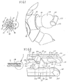
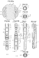
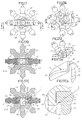
- Figure 1 is a perspective view and detail partial augmented by the connector, according to one version chosen: from eight members or pivots.
- Figure 2 is a perspective view and detail partial increased by the structural element.
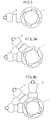
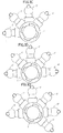
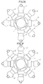
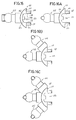
- Figures 3 to 3k correlatively are examples various of the connector member of FIG. 1 with a number different from 45 °, 90 °, 120 ° and 180 ° radial pivots.
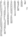
- Figure 4 is a table showing the dimensions different (length) A to H of structural elements (rods) straight.
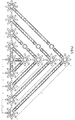
- Figure 5 is a table showing an embodiment structural possible, starting from an "A" dimension between the axes of the pivots, spaced by a structural element (A-H) of Figure 4.
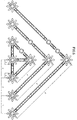
- Figure 6 is a representation equal to the previous one of a structural relation starting from a dimension "B" between the axes of two pivots spaced by one or several structural elements (A-H) in Figure 4.
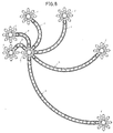
- Figure 7 is a table showing the dimensions different (arcs) (a-f) of the structural elements curvilinear (rods).
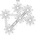
- Figure 8 is a representation of an example of free structural realization with the different members curvilinear in figure (7).
- Figures 9 and 10 are examples of modes of different structuring, according to a regular coaxial assembly or articulated connecting members and elements Figures 1 and 2, according to the invention.
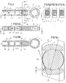
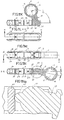
- Figure 11 is a plan view of the association coaxial of a connector member and a structural element.
- Figures 11a, 11b and 11c are sections transverse by lines A-A, C-C and E-E respectively of fig. 11.
- Figure 11A is a sectioned view longitudinally by line B-B in Figure 11.
- Figure 11B is a sectional view through line D-D of Figure 11A.
- Figure 11a is the enlarged detail of the figure 11a.
- Figure 11C is a survey view at 90 ° relative to the representation of figure 11, in an example of rotation.
- Figures 11Ca, 11Cd and 11Cc are sections transverse by lines D-D, A-A and E-E respectively of Figure 11C.
- Figure 11D is a sectioned view longitudinally by line B-B in Figure 11C.
- Figure 11E is a sectional view through line C-C of Figure 11D.
- Figure 11F is a 90 ° plan view of the figure 11C.
- Figure 11Ca ' is an enlarged detail of the figure 11Ca.
- Figure 11G is a top view of members of the Figure 11 in an example of articulation.
- Figure 11H is a 90 ° plan view of the figure 11G.
- Figure 11I is a sectional view through line A-A in Figure 11H.
- Figure 11J is a perspective plan view of the figure 11G.
- Figure 11K is a sectional view through line A-A of Figure 11L of the members of Figure 11 in a example of rotation.
- Figure 11L is a 90 ° plan view of the figure 11K.
- Figure 11M is a view equal to Figure 11L in extended position.
- Figure 11N is a sectional view through line A-A of Figure 11M.
- Figure 11Na is the enlarged detail of the figure 11N.
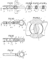
- Figure 12 is a top view of the threading or linking structural elements (rods).
- Figure 12A is a sectional view through line E-E of Figure 12B.
- Figure 12B is a sectional view through line D-D in Figure 12.
- Figure 12C is a cross sectional view by line A-A in figure 12.
- Figure 12Ca is a sectional view reproduced in large detail of Figure 12C.
- Figure 12D is a cross-sectional view by line C-C in figure 12.
- Figure 12E is a cross-sectional view by line B-B in Figure 12.
- Figure 12F is a related perspective view with figure 12.
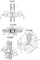
- Figure 13 is a perspective view of the assembly a structural rod in the housing connector element receiver.
- Figure 13A is a front elevation view of the representation of figure 13.
- Figure 13B is a sectional view through line A-A of Figure 13A.
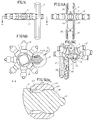
- Figure 14 is a side elevational view of the assembly of a radial member of a connector element in a housing -not external- of a structural rod.
- Figure 14A is a 90 ° front elevation view of the figure 14.
- Figure 14B is a sectional view through line A-A in Figure 14.
- Figure 14C is a perspective view of the representation of FIGS. 14A and 14B.
- Figure 14Ba is an enlarged view of the detail of figure 14B.
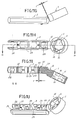
- Figure 15 is a plan view of an example of the alternative and / or staggered assembly of various elements connectors in a set (pair) of elements (rods) structural.
- Figure 15A is a sectional view through line A-A- in Figure 15.
- Figure 16 is a side elevational view of a member additional connector (auxiliary), with only one radial connector member (pivot).
- Figure 16A is a 90 ° elevation view of Figure 16.
- Figure 16B is a view equal to 16A of an element connector of the radial connector members (pivots).
- Figure 16C is a view equal to 16B of an element connector of three members radial connectors (pivots).
- Figure 17 is a front elevation view of the assembly perpendicular and symmetrically of two members of the Figure 16C, in a multiple connector element radial connector elements (pivots).
- Figure 17A is a perspective view of the figure 17.
- Figure 17B is a sectional view through line C-C in Figure 17.
- Figure 17C is a sectional view through line C-C in Figure 17.
- Figure 17D is a perspective view of the figure 16C.
- Figure 17Ca is an enlarged view of the detail of figure 17C.
- Figure 17Da is an enlarged view of the detail of Figure 17D.
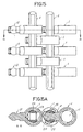
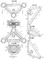
- Figure 18 is a raised view of the mounting of a straight structural rod with two elements complementary (auxiliary) connectors of the type of Figure 16 and following.
- Figure 18A is a sectional view through line A-A in Figure 18.
- Figure 18B is a perspective view of the figure 18.
- Figure 18Aa is an enlarged view of the detail of Figure 18A.
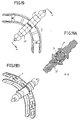
- Figure 19 is a plan view of the mounting of a curvilinear structural element (rod) with two elements complementary (auxiliary) connectors of the type of Figure 16 and following.
- Figure 19A is a sectional view through line A-A in Figure 19.
- Figure 19B is a perspective view of the figure 19.
- Figure 20 is a perspective view, in representing in perspective-lifted the stop element
- FIG. 20A is a perspective view, in representing in perspective-plan the stop element.
- FIG. 20B is a perspective view of said element of a stop engaged in a structural rod limiting a connector element threaded into said element (rod) structural.
- Figure 20C is a sectional view through line D-D of Figure 20D.
- Figure 20D is a top view of Figure 20B.
- Figure 20E is a sectional view through line A-A of Figure 20D.
- Figure 20F is a sectional view through line C-C of Figure 20E.
- Figure 21 is a perspective view shown in lifted from a limiting hub cover.
- FIG. 21A is a view similar to the previous one, shown in plan.
- FIG. 21B is a view in proyection of the mounting of the hub covers of FIGS. 21 and 21A mounted in the member extremity receiver of a structural rod.
- Figure 21C is a top view of Figure 21B partially sectioned by line A-A in Figure 21D.
- Figure 21 D is a plan view of Figure 21C.
- Figure 21E is a sectional view through line B-B in Figure 21C.
- Figure 21F is a sectional view through line C-C of Figure 21D.
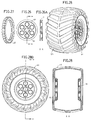
- Figure 22 is a top view of a rim element for a rolling member.
- Figure 22a is a 90 ° plan view of the figure 22.
- Figure 23 is a top view of a limb (pneumatic) bearing for the rim of figure 22.
- Figure 23A is a 90 ° plan view of the figure 23.
- Figure 24 is a top view of a rim element for a lower diameter bearing member.
- Figure 24A is a 90 ° plan view of the figure 24.
- Figure 25 is a top view of a limb (pneumatic) bearing for the rim of figure 24.
- Figure 25A is a 90 ° plan view of the figure 25.
- Figure 26 is a top view of a rim element for a tire with a small cross-section.
- Figure 26A is a sectional view through line A-A in Figure 26.
- Figure 27 is a perspective view of an element tire for the rim in Figures 26-26A.
- Figure 28 is a large pneumatic element section consisting of a set (pair) of rims in Figures 26-26A.
- Figure 28A is a top view of Figure 28.
- Figure 28B is a sectional view through line A-A of Figure 28A.
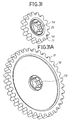
- Figure 29 is a raised view of a member for the mounting tracks in tires.
- Figure 30 is a perspective view of a tire mounted with the member of figure 29 in a example of chain-caterpillar.
- Figure 30A is a plan view with respect to the figure 30.
- Figure 30B is a survey view at 90 ° relative to Figure 30A.
- Figure 31 is a perspective view of an organ small diameter gear.
- Figure 31A is a similar view to the front of a large gear member.
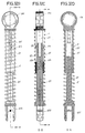
- Figure 32 is a perspective view of the male member a suspension element (shock absorber).
- Figure 32A is a perspective view of the limb female of a suspension element (shock absorber).
- FIG. 32B is a view in elevation of a member of suspension mounted according to the members of Figures 32 and 32A.
- Figure 32C is a sectional view through line B-B of Figure 32B.
- Figure 32D is a sectional view through line A-A of Figure 32C.
- Figure 33 is a perspective view from below of a triangular piece for closure.
- FIG. 33A is a view similar to the previous one in a shortened position.
- FIG. 33B is a view similar to the previous ones by up.
- Figure 33C is a plan view of the workpiece closure of FIGS. 33 to 33B on the structure.
- Figure 33D is a sectional view through line A-A in Figure 33C.
- Figure 33E is a plan view less than 180 ° from Figure 33C.
- Figure 33F is an enlarged view of the detail of figure 33D.
- Figure 34 is a plan view of an example of combined closure in various dimensions.
- Figure 34A is a sectional view through line A-A in Figure 34.
- Figure 35 is a plan view of a member connector in mixed spider in an example of connection.
- Figure 35A is a perspective view of the figure anterior.
- Figure 1 shows the element, named below “connector”, generally by (1) and in Figure 2 the structural element, hereinafter called “rod” indicated from generally by (2).
- the connector (1) is a basically circular piece or annular drum (10) with a concentric housing and openwork (through) (11), which has means in the outline embedding or threading, swaging or bayonet (15), (16), distributed in two bands (13) (14), symmetrical, one on each side, alternating alternately the ratio of the female (15) -male (16) jointing elements and male (16) - female (15).
- This provision determines the fact of being able to climb on both sides of a drum (10) an element of the structure which has means or which is provided with means for threading in such bouvillage members (15) (16) so that through the female organs (15) and moving them a quarter of a turn, they hang against the inner edge (17) of the male organs.
- Said jointing members (15) (16) are notches (15) and teeth (16) with a preferred shape in dovetail.
- the male connector members (12) are projected radially from the outer contour of the drum annular (10), hereinafter called “plugs", male (12) at number of up to eight 45 ° cards, bringing to the invention of connectors of one, two, three, four, five, six, seven and eight cards (12), according to Figures 3 to 3F; two 90 °, 135 ° and 180 ° plugs, according to the figures 3G to 3I; and three and four 90 ° plugs in Figures 3J and 3K.
- the radial plugs (12) are pivots substantially cylindrical. They are made up of base (18) and barrel (19) which are cylindrical sectors of different sections.
- the head (100) is a body spherical and the crest (101) is a prismatic boss cotangiel at the free pole of the sphere and finished in a way rounded and bevelled edges (103).
- the head (100) is the ball joint member which is embedded in the rod receiving receptacles (2), in snapping into these with the ability to turn and articulate bilaterally to an angle whose limitation determines the dividing wall (22) which is the bottom of said receiver, while the crest (101) is the office of abutment against said dividing partition (22) in allowing the movements of the head (100) to be not in difficulty because of friction, by collaborating the blunt tip (102) and bevels (103).
- the rods (2) are female elements of the structure according to the invention, consisting of parts of beam-shaped ashamedy made up of two parts of equal and parallel "wings" (21-21A) fixed transversely by dividing partitions (22) of the same height as said wings, and others (23) interspersed between these which have a lower height and which are centered between the marginal edges of the wings (21-21A).
- the rods (2) have receptacles (24) for their ends, open in the shape of a "U” and others intermediate receiving housings (25) open from both sides of the rod.
- the lateral edges (27) of the breasts (26) are weakly labeled to facilitate entry lateral of the heads (100) of the plugs (12) and also for cross the positions of said sheet (12) when the barrel (19) coincides with the margins (27) in their phases of articulation.
- the invention allows the option inserting or inserting the plugs (12) laterally in receivers (24), this operation can also advantageously be carried out coaxially to the organ receiver (20) and therefore to the extreme receiver housing (24), presenting the end edges of the wings (21) (21A), inside, bevelled (28) to facilitate this housing, the extreme sectors (200-201) yielding to the pressure of the heads (100) by the effect of the character or elastic condition of plastics, for example: Density PVC etc., used for the manufacture of these rooms.
- the dividing partition (22) regularly spaced, according to the length of the rod (2) in accordance with dimensions shown in Figure 4, using the formula known according to the development of the hypotenuse of a triangle rectangle as a catheter of the complementary triangle progressive, is made by the side facing the wall to, without additional elements or means, allow assembly to unidirectionally connect and successively two or more members of the same family, that is to say, two or more rods (2), according to the examples shown in Figures 12 to 12F.
- the dividing partitions (22) are internally provided with a figure composed by large vertical cylindrical ribs (202-203), tangent and partially soaked in the walls (204-205) resulting in their respective ends a small interior steps (206-207).
- cylindrical ribs (202-203) in particular top and bottom, centrally, is an extension (208) of curvilinear profile and with an equivalent height to that of the echelon (206-207), ending at the same height than the marginal edges of the wings (21-21A).
- Said marginal edges have a beveled labiate (209-210), entering, to facilitate the coupling of said edges in unidirectional installation of rods (2-2A) according to FIGS. 12 to 12F represent and more particularly, the section of Figure 12D which shows the overlap of bevelled edges (209-210) of said rods (2-2A).
- Said covering allows the breasts (26) of receiving housings (24) engage against extensions (208) whose curvilinear profile mates perfectly against the spherical bottom of the breasts (26), where the elastic coefficient of the material also cooperates plastic used in manufacturing and tolerance slightly less than that of the height (d) between the walls (200-201) of the receiver (24), by exerting a some pressure when fitting rods (2-2A) to cross the interlocking extensions (208), including the curvilinear profile, favors the displacement of the rods (2-2A) when these are introduced, vice versa, one inside the other.
- the projection of the arch of the breasts (26) also favors the exit of the rods (2-2A) during their disassembly.
- the interleaved partition walls (23) have a height less than that of the walls (204-205) in a equal portion from above and below (211-212) (figures 11A-11D-11J-11K-11L-11M-11N) to cross space necessary for the walls (200-201) in the assembly of rods (2-2A) shown in Figures 12 to 12F.
- the spaces between the dividing walls (22) and the intermediaries (23) are the accommodation intermediate receivers (25).
- These accommodations in walls (204 and 205) which delimit the space, are provided anchoring means for the plugs (12) for connecting the connectors (1).
- These means are partial dips, vertical and medium height (213), cut in half equal parts by a wall fragment (214) oriented towards both sides of said walls (204-205).
- the system also provides for the mounting of the rods (2) by means of the connector (1) through the annular housing (11) of the drum (10).
- This assembly is carried out by introducing the rod (2) in the logmeent (11) along it, adjusting its outer contour against the dovetail teeth (16), reason, the external longitudinal edges (216) wings (21-21A), are bevelled in planes tilted outwards to be partially placed in the curvilinear wall of said teeth (16) according to the figure 13B, facilitating the possibility of rotation and sliding in the rod (2) in the receiver housing (11), while the ends (217) of said wings (21-21A) are bevelled to facilitate the insertion of the rod (2) in such a receiving housing (1).
- FIGS. 14 to 14C and the Figures 13 to 13B allow a composition to be produced combined with alternative assemblies, for example series interleaved parallel connectors (1) and two rods common parallels (2), as shown in Figures 15-15A drawings.
- the invention in addition to the set of straight rods 2A at 2 hours in FIG. 4, advantageously provides a set of curvilinear rods 2a to 2f of Figure 7, where the dimensions of the strings of their respective arcs coincide exactly with that of their straight analogs, in can compose similar triangular sectors of so that their receiving ends coincide with the connection plugs (12) of the connectors (1) which are located at the distances required by the rods (2F) (2a-2f) corresponding, according to a schematic representation and in radial projections from a connector node common (1).
- the invention also advantageously allows the realization of structures that meet the basic pattern of the triangular development of Figures 5 and 6, make up multiple geometric figures following the condition of rotation and articulated mounting between rods (2) and connectors (1), described previously, and represented in FIGS. 11 to 11Na.
- the invention also advantageously presents a member partial connector (110) ( Figures 16 to 16C) and Figures 17 at 17Da which has the dual ability to slip on with the connectors (1) or with the rods (2).
- the partial connector (110) consists of a circular sector (111) of the annular cube (110) of the connector (1) which has an arc capable of projecting radially one, two or three cards (112) equal to connector plugs (12) (1), ( Figures 1 and 3a 3K).
- Opposite said sheets (112) project parallel arched plugs (114-115) outside and straight inside (113) to fit into the rods (2) and an external dimension between (114 and 115), to fit into the housing (11) of the connector (1).
- the pins (114-115) at the end lower free are provided with a boss exterior (116-117) with degressive extension towards its ends which, by inserting said pins (114-115) in the circular housing (11) of the connector (1) in passing said pins (114-115) between two diametrically opposite notches (15) and by turning a quarter turn the part (110), the bosses (116-117) will snap against the internal edge (17) of the two teeth (16) which divide the inside diameter half by half of the housing (11) and half to half, the height thereof, by alternating the arrangement of these.
- Said pins (114-115) also have internally mid-height of the ribs (118-119) parallel to the ends free from the pins (114-115) and aligned with them, in the bottom of the recess (113) have vertices bevelled (121-122) and, between them, a central projection (120) which constitutes the limit of the accommodation (113).
- Said configuration makes it possible to mount the pieces of connection (110) in the straight rods (2) or curvilinear ( Figures 18 to 18B and 19 to 19B), being able to locate, two aligned pieces (100) in a wing (21) and (21A) respectively, as shown in said figures.
- the housing (113) is mounted on the wings (21-21A) indiscriminately. They can be mounted perpendicular to the wings (21-21A) or by guiding it along these, introducing them through one end of the rod (2) so that the ribs (118-119) thread against the inner edges of the wings (21-21A), the boss (120) of the bottom of the housing (113) making the abutment office.
- the blunt profile of the ribs (118-119) makes mounting and dismounting possible against the wings (21-21A), which is facilitated by the elastic coefficient of the plastic used in the manufacture of said parts. This provision allows that the part (110) can move between two recesses intermediate (25) by crossing the partition (23) where its lower height does not prevent the passage of the ribs (118-119) of the recess (113).
- the system incorporates an immobilizer of the mounting of the rod (2) and connector (1) when it is mounted in the housing (11) thereof.
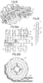
- Said immobilizing member shown in the figures 20 to 20F, is composed of a dihedral body (30) (parallelepiped) fitted with an embedding member or half-plug (31) perpendicular and axial to one of their sides and composed of a barrel or neck (32) and a spherical head (33), while by a base of the body (30) in adjoining position to the member (31) it is provided with a prismatic appendage (34) in circular wedge with key mode.
- the asset is produced by embedding the head (33) between two recesses opposite (213) under the same conditions as the case shown Figures 14B and 14Ba; while the key (34) is housed in one of the dovetail notches (15) housing (11) of the connector (1) according to the watch in particular figure 20F by making the office of stop against the edge inside (17) of the tooth (16) opposite this notch (15) in said housing (11).
- the system also incorporates a hub cover part, can be connected in the receiver housing (24) rods (2) which behave like an axis or which make the office of an axis for a rolling member, a body of rotation etc.
- Said hub cover is a part (40) defined by a discoid cover (41) or an associated head with a plug fork (42) consisting of two pins flat (43-44) separated by a space (45) and laterally on the outside, each provided with a circular recess (46-47) and a free end ending in a song beveled (47-48).
- the head (41), on the outside, is provided with cross ribs (49)
- the part (40) is mounted by means of a fork (42) in the housing (24) of the rods (2) so that its lenticular indentations (46-47) fit into the breasts (26) of said receiving housing (24).
- the head (41) is the office of middle cover and stopper for mounting in said rod (2) of one of the above elements.
- the system provides a set of rims with its wheels which, as a special feature, first presents the connecting members of the invention and below to compose complements various dynamics, such as a chain-caterpillar.
- the rims shown in Figures 22-22A and 24-24A in two different dimensions indicated by (50) and (51) are grooved rims (52) (53), respectively, provided mounting means (54) (55) which are an element annular connector with the same characteristics as the housing (11) of the connector (1).
- Said rims (50-51) are intended respectively for the tires (60-61) of Figures 23-23A and 25-25A.
- a third rim (56), Figures 26-26A, also grooved (57) and with a housing (58) equal to that of the and intended for a tire with a narrow profile (62) figure 27, can be used in duplicate, Figure 28 to 28B, for a large tire (63) development, for an all-terrain or amphibious vehicle.
- This auxiliary member (70), Figure 29, is a rod cylindrical (71) based on the principle of plugs (1) which is provided with one or more annular bosses (72) which have a hemispherical profile likely to be embedded fitted in the two opposite breasts (26) rod (2) according to the invention.
- the rod (71) is finished at both ends by respective spherical heads (73) (74) which are homologous to the heads (100) of the files (12) and which are inserted into specially incisions formed in the surface design of tires.
- a tire (64) specially provided with a tread pattern (65), at the two margins of the incisions (66) of hemispherical transverse profile for the heads (73) or (74) of the rod (70) which, depending on the malleable coefficient of the material used in the manufacturing the tire (64), allows them to be embedded with some pressure.
- organs transmission such as gears of diameters different (75) (76)) ( Figures 31-31A) with a toothed profile semicircular teeth (77) and breasts (78) with the equivalent circular development which corresponds to size of spherical heads (100) of plugs (12) or heads spherical (73-74) rods (71) to engage in these for the purposes provided for in the invention and for these effects the gears (75) (76) are provided with connector means (79) identical to the means (10) of the connector (1).
- organs transmission such as gears of diameters different (75) (76)) ( Figures 31-31A) with a toothed profile semicircular teeth (77) and breasts (78) with the equivalent circular development which corresponds to size of spherical heads (100) of plugs (12) or heads spherical (73-74) rods (71) to engage in these for the purposes provided for in the invention and for these effects the gears (75) (76) are provided with connector means (79) identical to the
- FIGS. 32 to 32D are used to construct damping members of vehicles, machines, tools etc, which with the system proposed by the invention, can to be built
- the opposite element or accommodable end presents preferably, lateral anchoring means to avoid its incidental eviction, such as corner tabs (83) located on both sides of the pins (84) produced by a blind groove (85) cut on the inner end. In yielding this branch both during assembly and disassembly of said male member (81) in the female member (82).
- the female member (82) is a tubular member which the free end has identical connector means (86) to those of the means (10) of the connector (1) for accomplishing identical functions as this one and, along the barrel, it has opposite grooves (87-88) ( Figures 32C) which have an approximate length to two thirds of the barrel. AT through these grooves (87-88), when the female member (1) is housed, the tabs ending their race against end edges (89) opposite the connector (86) slide.
- the shock absorber is completed by incorporating a spring "R" between the connector head (86) and the pin reception (81A) of the female (82) and male (81) members and which, depending on the calculated tension, will hold in position said male (81) and female (82) members.
- system according to the invention incorporates closing gussets to cover the triangular spaces defined by the structure, according to all the solutions resulting from the combination determined by the proposed formula of adding to catheters of the complementary triangle the hypotenuse of the main triangle, as shown in Figures 5-6, which serve example in these illustrations.
- gussets are straight trinagular pieces (90) with sides internally beveled (91-91a-91b) and flattened peaks and arched (92-92a-92b) composed by two risers in projection on the base of the gusset (90).
- the fixing member (93) is associated with a hole (96) located in relation to the vertex (92a) formed by catheters (91-91b).
- Said fixing member (93) is consisting of two symmetrical projections (94-94a) in manhole, in profile in half barrel, with interior bosses (95-95a) which are the limbs to be recessed against the head (100) of the plug (12) of the connector (1) according to the figures 33D, 33E and 33F.
- the gussets (90) are adjusted in the hollow triangular defined by their connectors (1) and rods (2) corresponding so that when the injection member (93) snaps onto the head (100) of the plug (12) respective, the bevelled songs of the catheters (91-91a-91b) mate against respective beveled edges (216) wings (21-21A) of the rod (2) and the arched tops (92-92A-92B) against the respective edges of the drums (10) connectors (1).
- the versatility of the system proposed by the invention allows develop a structure to internally mount a frame, frame, hoop, etc., using a piece of regular cross at 90 ° (130), composed of drum (131) a connector (1) from which radial arms are projected (132-133-134-135), (in the clockwise direction watch) composed of receiving ends (24) of the rods (2), being able to each of them to receive cards respective (12) with their respective connectors (1).
Landscapes
- Toys (AREA)
Applications Claiming Priority (2)
| Application Number | Priority Date | Filing Date | Title |
|---|---|---|---|
| ES9601984 | 1996-09-19 | ||
| ES9601984A ES2123429B1 (es) | 1996-09-19 | 1996-09-19 | "sistema de construccion de juguetes" |
Publications (2)
| Publication Number | Publication Date |
|---|---|
| EP0830883A2 true EP0830883A2 (de) | 1998-03-25 |
| EP0830883A3 EP0830883A3 (de) | 1998-10-28 |
Family
ID=8296084
Family Applications (1)
| Application Number | Title | Priority Date | Filing Date |
|---|---|---|---|
| EP97500155A Withdrawn EP0830883A3 (de) | 1996-09-19 | 1997-09-05 | Spielzeugbausystem |
Country Status (3)
| Country | Link |
|---|---|
| EP (1) | EP0830883A3 (de) |
| JP (1) | JPH10127953A (de) |
| ES (1) | ES2123429B1 (de) |
Cited By (4)
| Publication number | Priority date | Publication date | Assignee | Title |
|---|---|---|---|---|
| EP0993851A3 (de) * | 1998-10-14 | 2003-01-15 | Lego A/S | Stossdämpfer für einen Spielzeugbausatz |
| US8157470B2 (en) * | 2005-09-22 | 2012-04-17 | Widee B.V. | Coupling between two objects, object intended therefor, and mocular building system |
| CN111350937A (zh) * | 2018-12-21 | 2020-06-30 | 上海交通大学 | 气动可调三角形平面多孔结构 |
| EP3677324A1 (de) * | 2019-01-04 | 2020-07-08 | Olivier Laurent Robache | Verbindungselement für baukasten, entsprechender stecker und baukasten |
Families Citing this family (10)
| Publication number | Priority date | Publication date | Assignee | Title |
|---|---|---|---|---|
| ES2176051B1 (es) * | 1999-06-18 | 2004-03-01 | Interlander Patermann S L | Construccion modular de juguete. |
| ES2185440B1 (es) * | 1999-12-14 | 2004-07-01 | Interlander Patermann, S.L. | Construccion de juguete en miniatura. |
| US6948998B2 (en) * | 2003-02-07 | 2005-09-27 | Jim Bagley | Interconnectable model construction elements |
| PL2629868T3 (pl) * | 2010-10-22 | 2015-01-30 | Lego As | Zestaw do budowy zabawki |
| KR200475730Y1 (ko) * | 2014-08-01 | 2014-12-30 | 허예령 | 조립식 입체 모형 구조물 |
| WO2017039410A1 (ko) * | 2015-09-04 | 2017-03-09 | 주식회사 짐월드 | 바퀴모형 조립형 연결부재 |
| KR101773024B1 (ko) * | 2015-11-19 | 2017-08-30 | 주식회사 아이스페이스 | 컨넥터 및 그를 포함하는 조립 완구 세트 |
| KR101873275B1 (ko) * | 2016-11-03 | 2018-07-02 | 주식회사 아이스페이스 | 로드 및 커넥터를 이용한 조립 완구 세트 |
| TR202018012A2 (tr) * | 2020-11-11 | 2020-11-23 | Turgut Hologlu | Eği̇ti̇m materyali̇ ve zeka oyunu |
| DE102022100400A1 (de) * | 2022-01-10 | 2023-07-13 | Doubleeagle Industry (China) Limited | Klemmbaustein |
Citations (3)
| Publication number | Priority date | Publication date | Assignee | Title |
|---|---|---|---|---|
| US5061219A (en) | 1990-12-11 | 1991-10-29 | Magic Mold Corporation | Construction toy |
| US5137486A (en) | 1990-12-11 | 1992-08-11 | Connector Set Toy Company | Multi-planar connector element for construction toy |
| US5350331A (en) | 1990-12-11 | 1994-09-27 | Connector Set Limited Partnership | Construction toy system |
Family Cites Families (5)
| Publication number | Priority date | Publication date | Assignee | Title |
|---|---|---|---|---|
| ES284150Y (es) * | 1985-01-25 | 1988-03-01 | Salcedo Sancho Julia | Nuevo juego espacial |
| US4758196A (en) * | 1987-03-27 | 1988-07-19 | Wang Tsung Hsien | Block unit for making three-dimensional blocks composed of geometric points, lines and planes |
| NO179545C (no) * | 1990-12-11 | 1996-10-30 | Connector Set Lp | Konstruksjonsleketöysystem |
| DE29506527U1 (de) * | 1995-04-15 | 1995-06-22 | Göpfert, Joachim, 99094 Erfurt | Baukastensystem |
| US5542871A (en) * | 1995-06-10 | 1996-08-06 | Matrix Toys, Ltd. | Rod for construction system |
-
1996
- 1996-09-19 ES ES9601984A patent/ES2123429B1/es not_active Expired - Lifetime
-
1997
- 1997-09-05 EP EP97500155A patent/EP0830883A3/de not_active Withdrawn
- 1997-09-18 JP JP27218597A patent/JPH10127953A/ja active Pending
Patent Citations (3)
| Publication number | Priority date | Publication date | Assignee | Title |
|---|---|---|---|---|
| US5061219A (en) | 1990-12-11 | 1991-10-29 | Magic Mold Corporation | Construction toy |
| US5137486A (en) | 1990-12-11 | 1992-08-11 | Connector Set Toy Company | Multi-planar connector element for construction toy |
| US5350331A (en) | 1990-12-11 | 1994-09-27 | Connector Set Limited Partnership | Construction toy system |
Cited By (5)
| Publication number | Priority date | Publication date | Assignee | Title |
|---|---|---|---|---|
| EP0993851A3 (de) * | 1998-10-14 | 2003-01-15 | Lego A/S | Stossdämpfer für einen Spielzeugbausatz |
| US8157470B2 (en) * | 2005-09-22 | 2012-04-17 | Widee B.V. | Coupling between two objects, object intended therefor, and mocular building system |
| CN111350937A (zh) * | 2018-12-21 | 2020-06-30 | 上海交通大学 | 气动可调三角形平面多孔结构 |
| EP3677324A1 (de) * | 2019-01-04 | 2020-07-08 | Olivier Laurent Robache | Verbindungselement für baukasten, entsprechender stecker und baukasten |
| FR3091488A1 (fr) * | 2019-01-04 | 2020-07-10 | Robache Olivier Laurent | Elément de liaison pour jeu de construction, embout associé et jeu de construction |
Also Published As
| Publication number | Publication date |
|---|---|
| EP0830883A3 (de) | 1998-10-28 |
| ES2123429B1 (es) | 1999-08-16 |
| JPH10127953A (ja) | 1998-05-19 |
| ES2123429A1 (es) | 1999-01-01 |
Similar Documents
| Publication | Publication Date | Title |
|---|---|---|
| EP0830883A2 (de) | Spielzeugbausystem | |
| BE1022467B1 (fr) | Labyrinthe cylindrique | |
| FR2549384A1 (fr) | Jouet modulaire | |
| BE1001456A3 (fr) | Jouet en forme d'arche de noe. | |
| CA2333425A1 (fr) | Jeu de strategie | |
| EP0807844A1 (de) | Abnehmbares Federscharnier für Brille | |
| FR2884153A1 (fr) | Raccord articule pour jouet de construction a pieces multiples | |
| EP0584025B1 (de) | Spielfigur für Fussballspiel und ihre Befestigung auf einer Stützstange | |
| FR2907558A1 (fr) | Elements de charniere elastique a grande amplitude pour monture de lunettes | |
| FR3067780A1 (fr) | Mecanisme de vis a rouleaux | |
| FR2866933A1 (fr) | Procede d'accouplement magnetique et dispositifs le mettant en oeuvre | |
| FR2618862A1 (fr) | Dispositif d'assemblage de tubes ou analogues comportant un logement en creux de forme cylindrique ou analogue | |
| FR2529819A1 (fr) | Procede de fabrication de structures composites en bois, et moyens pour sa mise en oeuvre | |
| FR2497463A1 (de) | ||
| EP0110800B1 (de) | Bauelementsatz | |
| FR2876169A1 (fr) | Element de cage de roulement | |
| FR2545565A1 (fr) | Chaine articulee support des conduits d'alimentation pour machine en mouvement | |
| FR2878759A1 (fr) | Ensemble d'elements pour un jeu de construction modulaire | |
| FR2587053A1 (fr) | Elements de construction, notamment pour la fabrication de cloisons et d'encadrements | |
| FR2683584A1 (fr) | Profile pour la realisation de volets-rideaux coulissants. | |
| FR2465913A1 (fr) | Noeud d'assemblage comportant des moyens de fixation pour le raccordement de pieces en forme de barre | |
| WO1986002415A1 (fr) | Objet tel que meuble comprenant des parties planes rigides assemblees angulairement et maintenues par des cles amovibles | |
| FR2915762A1 (fr) | Ouvrage formant barriere a montage longitudinal et procede de fabrication d'un tel ouvrage. | |
| FR2973346A1 (fr) | Structure pliable/deployable a deploiement spontane et verrouillage spontane a l'etat deploye | |
| FR2724573A1 (fr) | Puzzle jouet spherique |
Legal Events
| Date | Code | Title | Description |
|---|---|---|---|
| PUAI | Public reference made under article 153(3) epc to a published international application that has entered the european phase |
Free format text: ORIGINAL CODE: 0009012 |
|
| AK | Designated contracting states |
Kind code of ref document: A2 Designated state(s): AT BE CH DE DK ES FR GB GR IE IT LI LU MC NL PT SE |
|
| 17P | Request for examination filed |
Effective date: 19980303 |
|
| PUAL | Search report despatched |
Free format text: ORIGINAL CODE: 0009013 |
|
| AK | Designated contracting states |
Kind code of ref document: A3 Designated state(s): AT BE CH DE DK ES FR GB GR IE IT LI LU MC NL PT SE |
|
| RAP1 | Party data changed (applicant data changed or rights of an application transferred) |
Owner name: INTERLEGO A.G. Owner name: LEGO A/S |
|
| RIN1 | Information on inventor provided before grant (corrected) |
Inventor name: JOSA PATERMANN, FRANCISCO |
|
| AKX | Designation fees paid |
Free format text: AT BE CH DE DK ES FR GB GR IE IT LI LU MC NL PT SE |
|
| STAA | Information on the status of an ep patent application or granted ep patent |
Free format text: STATUS: THE APPLICATION HAS BEEN WITHDRAWN |
|
| 18W | Application withdrawn |
Withdrawal date: 20000413 |
|
| REG | Reference to a national code |
Ref country code: HK Ref legal event code: WD Ref document number: 1009410 Country of ref document: HK |