EP0830883A2 - Toy construction system - Google Patents
Toy construction system Download PDFInfo
- Publication number
- EP0830883A2 EP0830883A2 EP97500155A EP97500155A EP0830883A2 EP 0830883 A2 EP0830883 A2 EP 0830883A2 EP 97500155 A EP97500155 A EP 97500155A EP 97500155 A EP97500155 A EP 97500155A EP 0830883 A2 EP0830883 A2 EP 0830883A2
- Authority
- EP
- European Patent Office
- Prior art keywords
- construction system
- toy construction
- connector
- female
- elements
- Prior art date
- Legal status (The legal status is an assumption and is not a legal conclusion. Google has not performed a legal analysis and makes no representation as to the accuracy of the status listed.)
- Withdrawn
Links
Images


Classifications
-
- A—HUMAN NECESSITIES
- A63—SPORTS; GAMES; AMUSEMENTS
- A63H—TOYS, e.g. TOPS, DOLLS, HOOPS OR BUILDING BLOCKS
- A63H33/00—Other toys
- A63H33/04—Building blocks, strips, or similar building parts
- A63H33/10—Building blocks, strips, or similar building parts to be assembled by means of additional non-adhesive elements
- A63H33/101—Building blocks, strips, or similar building parts to be assembled by means of additional non-adhesive elements with clip or snap mechanism
Definitions
- the invention relates to a system for building toys and in particular, a new way of building and assembly of toys integrated by a plurality of elements, made of molded plastics with a certain rigidity and a ductile margin which allows effortlessly and with absolute simplicity, the assembly or the union between said elements.
- Connectors and structural elements which are developed based on proportional measures which starting from a basic portion and developed according to a known formula, are complemented to associate with each other by forming structures composed of a module triangular with right angles including the hypotenuse constitutes the catheter of the adjoining complementary triangle successive, gradually increasing the area of this, up to the maximum measurement allowed by the element longest structural member in the system.
- Proportional structural development proposed construction based on a principle mathematical or a known mathematical formula; elementary in educational references and substantially in the state of the art; for this guy of toy constructions, in the case of the invention, is advantageously integrated by structural elements straight and curvilinear structural elements multiples in a range of measures according to the formula aforementioned which, associated with a set of members specially developed by the invention, make it possible to form various coplanar or multiplanar compositions with multiple spatial projections.
- This capacity of the elements which mainly integrate the subject of the invention is also applicable for development and construction of a basic structure static like: a factory, a quay, a carousel ..., or dynamic like: vehicles, machinery, vessels, etc., or of a mixed nature such as: drawbridges, cranes, excavator, etc., allowing the construction of other complementary training basic structures, also static, dynamic or mixed, with multiple and diverse functions which equipped with self-propelled and controlled components or run from a remote control station, can perform their function within the structure of very basis of the construction or outside of it.
- a system where the radial nip elements are female terminals radially attached to an element annular equicentric between which are formed intermediate sections with trapezoid section and structural elements or pins or male members which fit into said pinching elements for compose a union where the male member can rotate freely in such tightening.
- the pinch shape between the female element and the male must be carried out laterally since the elements provided between each other prevent that the male element can be mounted or dismounted coaxially.
- the male structural element has its ends arranged to fit in and slip into the elements of pinch and its body, in wing section "X", to enter coaxially in the housing of the connector member, fit inside and be able to turn inside of it.
- Pinch elements can also adjust against the wing profile "X" of the male elements of the structure.
- the ability to develop the type of aforementioned structures is the special condition of connector elements and structural elements, according to the invention. It has means of coupling or not only admit rotation between them of these elements but also the articulation sort of patella, being able to vary the spatial projection of pieces at least at an angle of 115 ° which is the clearance between the male member of the connector element and the female member of the structural element which, essentially, are provided with a special definition of its coupling parts.
- said members, the male connector element and the female structural element bring associated means for mounting limbs in plane projections different and the second, moreover, means for receive other similar or complementary elements in transverse projections with applications different.
- the invention advantageously comprises an element annular connector with one or more members radial, substantially cylindrical, which have a spherical protuberance are terminated by a point extreme, which is a tangential prismatic boss and parallel to the symmetrical horizontal axis of said sphere and whose boss is finished by a blunt song so that the friction of this boss against the dividing wall of the housing for the female structural element, either not a flat friction and to allow that as well the free rotation movement as the articulated movement usual between connector and structural elements, find no friction resistance.
- the structural elements or rods are elements composed of two parts symmetrical, parallel and essentially separate planes by successive walls or partitions transverse to equidistance which form receptive housing intermediates and others, one at each end, open with coaxial access, as well as laterally, on both sides.
- the receptacles for extremes, open are designed for and have the capacity to receive the elements cylindrical connectors, being able to be mounted as well in a coaxial position relative to the linear access of the housing of said structural element, on one side or the other of the lateral openings of said housing, while the intermediate receiving housings are fitted out mainly to receive members transversely connectors, in particular the protuberance spherical, with a certain interlocking margin, and having the possibility to turn freely.
- intermediate dwellings are also fitted out with means which while being part of the wall of division with extreme receiver housing, allow or admit anchoring of another female structural member in reverse position (90 °), so that they adjust relatively by their respective longitudinal edges and in snapping, also relatively, against the parties specific to the dividing wall.
- the connector element is composed a drum or annular core which is hollowed out internally in a circular concentric housing, fitted in its outline with special cuts or tangential dovetail blasting, equidistant and at 90 °. This results alternately and also to equidistance the production of protrusions or bosses of same profile.
- These sections are connected vertically, by the two sides, up to half the height of the recess. Delays on one side and the other do not coincide not. They are alternative and their depth ends at the half of the recess.
- the housings of the connector element have, at least, a double mission. Admitting the assembly of the elements female structural perpendicularly, so that ability to slide axially and to rotate relatively inside the accommodation.
- the elements structural or rods have a geometric configuration very particular to be able to slide axially or be able to turn relatively and also to facilitate its introduction into the connector housing.
- connection pins radial may consist of connector elements multiples perpendicular to each other or interplanar in having up to 14 multiradial connection pins, in counting in this way on an orthogonal arrangement of eight pins in vertical projection and eight pins in horizontal projection.
- connector members can be complementary complementary bodies. By being composed of one, two or three connecting radial members, they have as long as a nucleus a circular fragment equivalent to an arc 120 ° annular drum, provided opposite to a means "U" anchor whose branches penetrate the housing of an annular connector, anchoring against internal edges of the bosses or tangential teeth of the walls of such accommodation.
- Said "U” anchoring members of the organ additional connector described have inside means which while being slightly elastic the pins of the "U” anchor, may staple against the edges of the wings of the structural elements, being able to have one or several connecting members on a structural element of the system.
- This version is used, both in the elements rectilinear structural, that curvilinear of the system, being given that the means of maintaining each other elements, have the same measures and the same characteristics.
- the system also incorporates stop members which snap into the intermediate housings of female structural elements which have a double mission depending on whether they are fixed in a position or in a other.
- it serves as a limiter to ensure the position, for example: of a connector element avoiding an axial displacement but without avoiding its movement of rotation and another to immobilize, for example, said connector element in both directions of such movements.
- the system also incorporates a member that snaps in the extreme housings of structural elements, in constituting an external stop for a member of this type, which serves as an axle for a wheel and which incorporates a rim with the housing of a connector element.
- a rim that has the grooved logic profile to receive a tire with various diameters, depending on that of the rim.
- a game of pair of rims serves as a drum to mount a wide tire, typical of all-terrain vehicles, planes, public works vehicles, amphibians, etc.
- the system incorporates tires molded in plastic or synthetic material, for example neoprene or the design of the cover, forms a lateral toothed profile, whose incisions are rooms for rooms composed with the profile of the male members of the connector, for example they are 180 ° rods without housing connector.
- These rods are arranged in said incisions and joining them circularly, each pair of rods, alternatively, with structural elements females, form a caterpillar chain by transforming a wheel set in one continuous track.
- a rim of the type indicated previously, according to the system, has an external toothing as as a gear, with a wavy toothed profile where the notches or incisions are housings for the male member of connector elements, for example: for a transmission.
- the system includes a suspension element consisting of telescopically assembled parts, with internal anchoring means to avoid eviction and a elastic member (a spring) threaded externally between these.
- Each telescopic member presents, at the end external respectively, an annular connector member and the extreme part of anchoring of a structural element female.
- Said suspension member is associated with elements of the system and can be used as a means shock absorber in vehicles, articulated devices, etc.
- the system ultimately incorporates a mixed member of spider for the interior mounting of four elements connectors, for example depending on a chassis or cross member composed of a connector member annular from which four structural elements are projected radially and equidistant, plus particular, four extreme means of assembling structural elements, which allow assembly in rotation and articulated male means of organs connectors.
- This allows, for example, the formation of rotating carousels; column frames, towers, etc.
- the system also incorporates a closure piece.
- a triangular piece to cover the hollow formed by the structural arrangement, depending on the system, of a set of connector elements and their structural elements correspondents.
- the system presented here has a versatility important to the construction of toys based on frames static or dynamic or a combination of the two, being able, essentially, to determine it by the condition differential assembly means, organs main connectors and structural elements - straight, curvilinear, build structures in different spatial projections not only coplanar, but also biplanar and multiplanar which can reach plan developments with a maximum inclination of 115 ° in relation to one of the surfaces mounted, according to the known triangular association formula described.
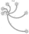
- the elements of curvilinear structures develop arched frames; arched structures or surfaces with a profile winding such as a railway, an air carrier; a winding profile carousel, etc.
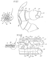
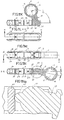
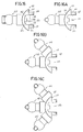
- Figure 1 is a perspective view and detail partial augmented by the connector, according to one version chosen: from eight members or pivots.
- Figure 2 is a perspective view and detail partial increased by the structural element.
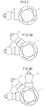
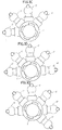
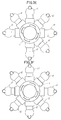
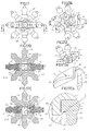
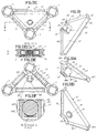
- Figures 3 to 3k correlatively are examples various of the connector member of FIG. 1 with a number different from 45 °, 90 °, 120 ° and 180 ° radial pivots.
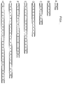
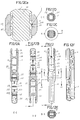
- Figure 4 is a table showing the dimensions different (length) A to H of structural elements (rods) straight.
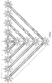
- Figure 5 is a table showing an embodiment structural possible, starting from an "A" dimension between the axes of the pivots, spaced by a structural element (A-H) of Figure 4.
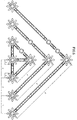
- Figure 6 is a representation equal to the previous one of a structural relation starting from a dimension "B" between the axes of two pivots spaced by one or several structural elements (A-H) in Figure 4.
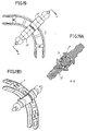
- Figure 7 is a table showing the dimensions different (arcs) (a-f) of the structural elements curvilinear (rods).
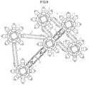
- Figure 8 is a representation of an example of free structural realization with the different members curvilinear in figure (7).
- Figures 9 and 10 are examples of modes of different structuring, according to a regular coaxial assembly or articulated connecting members and elements Figures 1 and 2, according to the invention.
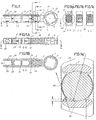
- Figure 11 is a plan view of the association coaxial of a connector member and a structural element.
- Figures 11a, 11b and 11c are sections transverse by lines A-A, C-C and E-E respectively of fig. 11.
- Figure 11A is a sectioned view longitudinally by line B-B in Figure 11.
- Figure 11B is a sectional view through line D-D of Figure 11A.
- Figure 11a is the enlarged detail of the figure 11a.
- Figure 11C is a survey view at 90 ° relative to the representation of figure 11, in an example of rotation.
- Figures 11Ca, 11Cd and 11Cc are sections transverse by lines D-D, A-A and E-E respectively of Figure 11C.
- Figure 11D is a sectioned view longitudinally by line B-B in Figure 11C.
- Figure 11E is a sectional view through line C-C of Figure 11D.
- Figure 11F is a 90 ° plan view of the figure 11C.
- Figure 11Ca ' is an enlarged detail of the figure 11Ca.
- Figure 11G is a top view of members of the Figure 11 in an example of articulation.
- Figure 11H is a 90 ° plan view of the figure 11G.
- Figure 11I is a sectional view through line A-A in Figure 11H.
- Figure 11J is a perspective plan view of the figure 11G.
- Figure 11K is a sectional view through line A-A of Figure 11L of the members of Figure 11 in a example of rotation.
- Figure 11L is a 90 ° plan view of the figure 11K.
- Figure 11M is a view equal to Figure 11L in extended position.
- Figure 11N is a sectional view through line A-A of Figure 11M.
- Figure 11Na is the enlarged detail of the figure 11N.
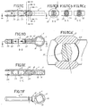
- Figure 12 is a top view of the threading or linking structural elements (rods).
- Figure 12A is a sectional view through line E-E of Figure 12B.
- Figure 12B is a sectional view through line D-D in Figure 12.
- Figure 12C is a cross sectional view by line A-A in figure 12.
- Figure 12Ca is a sectional view reproduced in large detail of Figure 12C.
- Figure 12D is a cross-sectional view by line C-C in figure 12.
- Figure 12E is a cross-sectional view by line B-B in Figure 12.
- Figure 12F is a related perspective view with figure 12.
- Figure 13 is a perspective view of the assembly a structural rod in the housing connector element receiver.
- Figure 13A is a front elevation view of the representation of figure 13.
- Figure 13B is a sectional view through line A-A of Figure 13A.
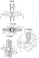
- Figure 14 is a side elevational view of the assembly of a radial member of a connector element in a housing -not external- of a structural rod.
- Figure 14A is a 90 ° front elevation view of the figure 14.
- Figure 14B is a sectional view through line A-A in Figure 14.
- Figure 14C is a perspective view of the representation of FIGS. 14A and 14B.
- Figure 14Ba is an enlarged view of the detail of figure 14B.
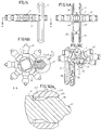
- Figure 15 is a plan view of an example of the alternative and / or staggered assembly of various elements connectors in a set (pair) of elements (rods) structural.
- Figure 15A is a sectional view through line A-A- in Figure 15.
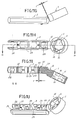
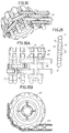
- Figure 16 is a side elevational view of a member additional connector (auxiliary), with only one radial connector member (pivot).
- Figure 16A is a 90 ° elevation view of Figure 16.
- Figure 16B is a view equal to 16A of an element connector of the radial connector members (pivots).
- Figure 16C is a view equal to 16B of an element connector of three members radial connectors (pivots).
- Figure 17 is a front elevation view of the assembly perpendicular and symmetrically of two members of the Figure 16C, in a multiple connector element radial connector elements (pivots).
- Figure 17A is a perspective view of the figure 17.
- Figure 17B is a sectional view through line C-C in Figure 17.
- Figure 17C is a sectional view through line C-C in Figure 17.
- Figure 17D is a perspective view of the figure 16C.
- Figure 17Ca is an enlarged view of the detail of figure 17C.
- Figure 17Da is an enlarged view of the detail of Figure 17D.
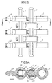
- Figure 18 is a raised view of the mounting of a straight structural rod with two elements complementary (auxiliary) connectors of the type of Figure 16 and following.
- Figure 18A is a sectional view through line A-A in Figure 18.
- Figure 18B is a perspective view of the figure 18.
- Figure 18Aa is an enlarged view of the detail of Figure 18A.
- Figure 19 is a plan view of the mounting of a curvilinear structural element (rod) with two elements complementary (auxiliary) connectors of the type of Figure 16 and following.
- Figure 19A is a sectional view through line A-A in Figure 19.
- Figure 19B is a perspective view of the figure 19.
- Figure 20 is a perspective view, in representing in perspective-lifted the stop element
- FIG. 20A is a perspective view, in representing in perspective-plan the stop element.
- FIG. 20B is a perspective view of said element of a stop engaged in a structural rod limiting a connector element threaded into said element (rod) structural.
- Figure 20C is a sectional view through line D-D of Figure 20D.
- Figure 20D is a top view of Figure 20B.
- Figure 20E is a sectional view through line A-A of Figure 20D.
- Figure 20F is a sectional view through line C-C of Figure 20E.
- Figure 21 is a perspective view shown in lifted from a limiting hub cover.
- FIG. 21A is a view similar to the previous one, shown in plan.
- FIG. 21B is a view in proyection of the mounting of the hub covers of FIGS. 21 and 21A mounted in the member extremity receiver of a structural rod.
- Figure 21C is a top view of Figure 21B partially sectioned by line A-A in Figure 21D.
- Figure 21 D is a plan view of Figure 21C.
- Figure 21E is a sectional view through line B-B in Figure 21C.
- Figure 21F is a sectional view through line C-C of Figure 21D.
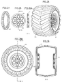
- Figure 22 is a top view of a rim element for a rolling member.
- Figure 22a is a 90 ° plan view of the figure 22.
- Figure 23 is a top view of a limb (pneumatic) bearing for the rim of figure 22.
- Figure 23A is a 90 ° plan view of the figure 23.
- Figure 24 is a top view of a rim element for a lower diameter bearing member.
- Figure 24A is a 90 ° plan view of the figure 24.
- Figure 25 is a top view of a limb (pneumatic) bearing for the rim of figure 24.
- Figure 25A is a 90 ° plan view of the figure 25.
- Figure 26 is a top view of a rim element for a tire with a small cross-section.
- Figure 26A is a sectional view through line A-A in Figure 26.
- Figure 27 is a perspective view of an element tire for the rim in Figures 26-26A.
- Figure 28 is a large pneumatic element section consisting of a set (pair) of rims in Figures 26-26A.
- Figure 28A is a top view of Figure 28.
- Figure 28B is a sectional view through line A-A of Figure 28A.
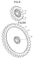
- Figure 29 is a raised view of a member for the mounting tracks in tires.
- Figure 30 is a perspective view of a tire mounted with the member of figure 29 in a example of chain-caterpillar.
- Figure 30A is a plan view with respect to the figure 30.
- Figure 30B is a survey view at 90 ° relative to Figure 30A.
- Figure 31 is a perspective view of an organ small diameter gear.
- Figure 31A is a similar view to the front of a large gear member.
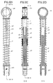
- Figure 32 is a perspective view of the male member a suspension element (shock absorber).
- Figure 32A is a perspective view of the limb female of a suspension element (shock absorber).
- FIG. 32B is a view in elevation of a member of suspension mounted according to the members of Figures 32 and 32A.
- Figure 32C is a sectional view through line B-B of Figure 32B.
- Figure 32D is a sectional view through line A-A of Figure 32C.
- Figure 33 is a perspective view from below of a triangular piece for closure.
- FIG. 33A is a view similar to the previous one in a shortened position.
- FIG. 33B is a view similar to the previous ones by up.
- Figure 33C is a plan view of the workpiece closure of FIGS. 33 to 33B on the structure.
- Figure 33D is a sectional view through line A-A in Figure 33C.
- Figure 33E is a plan view less than 180 ° from Figure 33C.
- Figure 33F is an enlarged view of the detail of figure 33D.
- Figure 34 is a plan view of an example of combined closure in various dimensions.
- Figure 34A is a sectional view through line A-A in Figure 34.
- Figure 35 is a plan view of a member connector in mixed spider in an example of connection.
- Figure 35A is a perspective view of the figure anterior.
- Figure 1 shows the element, named below “connector”, generally by (1) and in Figure 2 the structural element, hereinafter called “rod” indicated from generally by (2).
- the connector (1) is a basically circular piece or annular drum (10) with a concentric housing and openwork (through) (11), which has means in the outline embedding or threading, swaging or bayonet (15), (16), distributed in two bands (13) (14), symmetrical, one on each side, alternating alternately the ratio of the female (15) -male (16) jointing elements and male (16) - female (15).
- This provision determines the fact of being able to climb on both sides of a drum (10) an element of the structure which has means or which is provided with means for threading in such bouvillage members (15) (16) so that through the female organs (15) and moving them a quarter of a turn, they hang against the inner edge (17) of the male organs.
- Said jointing members (15) (16) are notches (15) and teeth (16) with a preferred shape in dovetail.
- the male connector members (12) are projected radially from the outer contour of the drum annular (10), hereinafter called “plugs", male (12) at number of up to eight 45 ° cards, bringing to the invention of connectors of one, two, three, four, five, six, seven and eight cards (12), according to Figures 3 to 3F; two 90 °, 135 ° and 180 ° plugs, according to the figures 3G to 3I; and three and four 90 ° plugs in Figures 3J and 3K.
- the radial plugs (12) are pivots substantially cylindrical. They are made up of base (18) and barrel (19) which are cylindrical sectors of different sections.
- the head (100) is a body spherical and the crest (101) is a prismatic boss cotangiel at the free pole of the sphere and finished in a way rounded and bevelled edges (103).
- the head (100) is the ball joint member which is embedded in the rod receiving receptacles (2), in snapping into these with the ability to turn and articulate bilaterally to an angle whose limitation determines the dividing wall (22) which is the bottom of said receiver, while the crest (101) is the office of abutment against said dividing partition (22) in allowing the movements of the head (100) to be not in difficulty because of friction, by collaborating the blunt tip (102) and bevels (103).
- the rods (2) are female elements of the structure according to the invention, consisting of parts of beam-shaped ashamedy made up of two parts of equal and parallel "wings" (21-21A) fixed transversely by dividing partitions (22) of the same height as said wings, and others (23) interspersed between these which have a lower height and which are centered between the marginal edges of the wings (21-21A).
- the rods (2) have receptacles (24) for their ends, open in the shape of a "U” and others intermediate receiving housings (25) open from both sides of the rod.
- the lateral edges (27) of the breasts (26) are weakly labeled to facilitate entry lateral of the heads (100) of the plugs (12) and also for cross the positions of said sheet (12) when the barrel (19) coincides with the margins (27) in their phases of articulation.
- the invention allows the option inserting or inserting the plugs (12) laterally in receivers (24), this operation can also advantageously be carried out coaxially to the organ receiver (20) and therefore to the extreme receiver housing (24), presenting the end edges of the wings (21) (21A), inside, bevelled (28) to facilitate this housing, the extreme sectors (200-201) yielding to the pressure of the heads (100) by the effect of the character or elastic condition of plastics, for example: Density PVC etc., used for the manufacture of these rooms.
- the dividing partition (22) regularly spaced, according to the length of the rod (2) in accordance with dimensions shown in Figure 4, using the formula known according to the development of the hypotenuse of a triangle rectangle as a catheter of the complementary triangle progressive, is made by the side facing the wall to, without additional elements or means, allow assembly to unidirectionally connect and successively two or more members of the same family, that is to say, two or more rods (2), according to the examples shown in Figures 12 to 12F.
- the dividing partitions (22) are internally provided with a figure composed by large vertical cylindrical ribs (202-203), tangent and partially soaked in the walls (204-205) resulting in their respective ends a small interior steps (206-207).
- cylindrical ribs (202-203) in particular top and bottom, centrally, is an extension (208) of curvilinear profile and with an equivalent height to that of the echelon (206-207), ending at the same height than the marginal edges of the wings (21-21A).
- Said marginal edges have a beveled labiate (209-210), entering, to facilitate the coupling of said edges in unidirectional installation of rods (2-2A) according to FIGS. 12 to 12F represent and more particularly, the section of Figure 12D which shows the overlap of bevelled edges (209-210) of said rods (2-2A).
- Said covering allows the breasts (26) of receiving housings (24) engage against extensions (208) whose curvilinear profile mates perfectly against the spherical bottom of the breasts (26), where the elastic coefficient of the material also cooperates plastic used in manufacturing and tolerance slightly less than that of the height (d) between the walls (200-201) of the receiver (24), by exerting a some pressure when fitting rods (2-2A) to cross the interlocking extensions (208), including the curvilinear profile, favors the displacement of the rods (2-2A) when these are introduced, vice versa, one inside the other.
- the projection of the arch of the breasts (26) also favors the exit of the rods (2-2A) during their disassembly.
- the interleaved partition walls (23) have a height less than that of the walls (204-205) in a equal portion from above and below (211-212) (figures 11A-11D-11J-11K-11L-11M-11N) to cross space necessary for the walls (200-201) in the assembly of rods (2-2A) shown in Figures 12 to 12F.
- the spaces between the dividing walls (22) and the intermediaries (23) are the accommodation intermediate receivers (25).
- These accommodations in walls (204 and 205) which delimit the space, are provided anchoring means for the plugs (12) for connecting the connectors (1).
- These means are partial dips, vertical and medium height (213), cut in half equal parts by a wall fragment (214) oriented towards both sides of said walls (204-205).
- the system also provides for the mounting of the rods (2) by means of the connector (1) through the annular housing (11) of the drum (10).
- This assembly is carried out by introducing the rod (2) in the logmeent (11) along it, adjusting its outer contour against the dovetail teeth (16), reason, the external longitudinal edges (216) wings (21-21A), are bevelled in planes tilted outwards to be partially placed in the curvilinear wall of said teeth (16) according to the figure 13B, facilitating the possibility of rotation and sliding in the rod (2) in the receiver housing (11), while the ends (217) of said wings (21-21A) are bevelled to facilitate the insertion of the rod (2) in such a receiving housing (1).
- FIGS. 14 to 14C and the Figures 13 to 13B allow a composition to be produced combined with alternative assemblies, for example series interleaved parallel connectors (1) and two rods common parallels (2), as shown in Figures 15-15A drawings.
- the invention in addition to the set of straight rods 2A at 2 hours in FIG. 4, advantageously provides a set of curvilinear rods 2a to 2f of Figure 7, where the dimensions of the strings of their respective arcs coincide exactly with that of their straight analogs, in can compose similar triangular sectors of so that their receiving ends coincide with the connection plugs (12) of the connectors (1) which are located at the distances required by the rods (2F) (2a-2f) corresponding, according to a schematic representation and in radial projections from a connector node common (1).
- the invention also advantageously allows the realization of structures that meet the basic pattern of the triangular development of Figures 5 and 6, make up multiple geometric figures following the condition of rotation and articulated mounting between rods (2) and connectors (1), described previously, and represented in FIGS. 11 to 11Na.
- the invention also advantageously presents a member partial connector (110) ( Figures 16 to 16C) and Figures 17 at 17Da which has the dual ability to slip on with the connectors (1) or with the rods (2).
- the partial connector (110) consists of a circular sector (111) of the annular cube (110) of the connector (1) which has an arc capable of projecting radially one, two or three cards (112) equal to connector plugs (12) (1), ( Figures 1 and 3a 3K).
- Opposite said sheets (112) project parallel arched plugs (114-115) outside and straight inside (113) to fit into the rods (2) and an external dimension between (114 and 115), to fit into the housing (11) of the connector (1).
- the pins (114-115) at the end lower free are provided with a boss exterior (116-117) with degressive extension towards its ends which, by inserting said pins (114-115) in the circular housing (11) of the connector (1) in passing said pins (114-115) between two diametrically opposite notches (15) and by turning a quarter turn the part (110), the bosses (116-117) will snap against the internal edge (17) of the two teeth (16) which divide the inside diameter half by half of the housing (11) and half to half, the height thereof, by alternating the arrangement of these.
- Said pins (114-115) also have internally mid-height of the ribs (118-119) parallel to the ends free from the pins (114-115) and aligned with them, in the bottom of the recess (113) have vertices bevelled (121-122) and, between them, a central projection (120) which constitutes the limit of the accommodation (113).
- Said configuration makes it possible to mount the pieces of connection (110) in the straight rods (2) or curvilinear ( Figures 18 to 18B and 19 to 19B), being able to locate, two aligned pieces (100) in a wing (21) and (21A) respectively, as shown in said figures.
- the housing (113) is mounted on the wings (21-21A) indiscriminately. They can be mounted perpendicular to the wings (21-21A) or by guiding it along these, introducing them through one end of the rod (2) so that the ribs (118-119) thread against the inner edges of the wings (21-21A), the boss (120) of the bottom of the housing (113) making the abutment office.
- the blunt profile of the ribs (118-119) makes mounting and dismounting possible against the wings (21-21A), which is facilitated by the elastic coefficient of the plastic used in the manufacture of said parts. This provision allows that the part (110) can move between two recesses intermediate (25) by crossing the partition (23) where its lower height does not prevent the passage of the ribs (118-119) of the recess (113).
- the system incorporates an immobilizer of the mounting of the rod (2) and connector (1) when it is mounted in the housing (11) thereof.
- Said immobilizing member shown in the figures 20 to 20F, is composed of a dihedral body (30) (parallelepiped) fitted with an embedding member or half-plug (31) perpendicular and axial to one of their sides and composed of a barrel or neck (32) and a spherical head (33), while by a base of the body (30) in adjoining position to the member (31) it is provided with a prismatic appendage (34) in circular wedge with key mode.
- the asset is produced by embedding the head (33) between two recesses opposite (213) under the same conditions as the case shown Figures 14B and 14Ba; while the key (34) is housed in one of the dovetail notches (15) housing (11) of the connector (1) according to the watch in particular figure 20F by making the office of stop against the edge inside (17) of the tooth (16) opposite this notch (15) in said housing (11).
- the system also incorporates a hub cover part, can be connected in the receiver housing (24) rods (2) which behave like an axis or which make the office of an axis for a rolling member, a body of rotation etc.
- Said hub cover is a part (40) defined by a discoid cover (41) or an associated head with a plug fork (42) consisting of two pins flat (43-44) separated by a space (45) and laterally on the outside, each provided with a circular recess (46-47) and a free end ending in a song beveled (47-48).
- the head (41), on the outside, is provided with cross ribs (49)
- the part (40) is mounted by means of a fork (42) in the housing (24) of the rods (2) so that its lenticular indentations (46-47) fit into the breasts (26) of said receiving housing (24).
- the head (41) is the office of middle cover and stopper for mounting in said rod (2) of one of the above elements.
- the system provides a set of rims with its wheels which, as a special feature, first presents the connecting members of the invention and below to compose complements various dynamics, such as a chain-caterpillar.
- the rims shown in Figures 22-22A and 24-24A in two different dimensions indicated by (50) and (51) are grooved rims (52) (53), respectively, provided mounting means (54) (55) which are an element annular connector with the same characteristics as the housing (11) of the connector (1).
- Said rims (50-51) are intended respectively for the tires (60-61) of Figures 23-23A and 25-25A.
- a third rim (56), Figures 26-26A, also grooved (57) and with a housing (58) equal to that of the and intended for a tire with a narrow profile (62) figure 27, can be used in duplicate, Figure 28 to 28B, for a large tire (63) development, for an all-terrain or amphibious vehicle.
- This auxiliary member (70), Figure 29, is a rod cylindrical (71) based on the principle of plugs (1) which is provided with one or more annular bosses (72) which have a hemispherical profile likely to be embedded fitted in the two opposite breasts (26) rod (2) according to the invention.
- the rod (71) is finished at both ends by respective spherical heads (73) (74) which are homologous to the heads (100) of the files (12) and which are inserted into specially incisions formed in the surface design of tires.
- a tire (64) specially provided with a tread pattern (65), at the two margins of the incisions (66) of hemispherical transverse profile for the heads (73) or (74) of the rod (70) which, depending on the malleable coefficient of the material used in the manufacturing the tire (64), allows them to be embedded with some pressure.
- organs transmission such as gears of diameters different (75) (76)) ( Figures 31-31A) with a toothed profile semicircular teeth (77) and breasts (78) with the equivalent circular development which corresponds to size of spherical heads (100) of plugs (12) or heads spherical (73-74) rods (71) to engage in these for the purposes provided for in the invention and for these effects the gears (75) (76) are provided with connector means (79) identical to the means (10) of the connector (1).
- organs transmission such as gears of diameters different (75) (76)) ( Figures 31-31A) with a toothed profile semicircular teeth (77) and breasts (78) with the equivalent circular development which corresponds to size of spherical heads (100) of plugs (12) or heads spherical (73-74) rods (71) to engage in these for the purposes provided for in the invention and for these effects the gears (75) (76) are provided with connector means (79) identical to the
- FIGS. 32 to 32D are used to construct damping members of vehicles, machines, tools etc, which with the system proposed by the invention, can to be built
- the opposite element or accommodable end presents preferably, lateral anchoring means to avoid its incidental eviction, such as corner tabs (83) located on both sides of the pins (84) produced by a blind groove (85) cut on the inner end. In yielding this branch both during assembly and disassembly of said male member (81) in the female member (82).
- the female member (82) is a tubular member which the free end has identical connector means (86) to those of the means (10) of the connector (1) for accomplishing identical functions as this one and, along the barrel, it has opposite grooves (87-88) ( Figures 32C) which have an approximate length to two thirds of the barrel. AT through these grooves (87-88), when the female member (1) is housed, the tabs ending their race against end edges (89) opposite the connector (86) slide.
- the shock absorber is completed by incorporating a spring "R" between the connector head (86) and the pin reception (81A) of the female (82) and male (81) members and which, depending on the calculated tension, will hold in position said male (81) and female (82) members.
- system according to the invention incorporates closing gussets to cover the triangular spaces defined by the structure, according to all the solutions resulting from the combination determined by the proposed formula of adding to catheters of the complementary triangle the hypotenuse of the main triangle, as shown in Figures 5-6, which serve example in these illustrations.
- gussets are straight trinagular pieces (90) with sides internally beveled (91-91a-91b) and flattened peaks and arched (92-92a-92b) composed by two risers in projection on the base of the gusset (90).
- the fixing member (93) is associated with a hole (96) located in relation to the vertex (92a) formed by catheters (91-91b).
- Said fixing member (93) is consisting of two symmetrical projections (94-94a) in manhole, in profile in half barrel, with interior bosses (95-95a) which are the limbs to be recessed against the head (100) of the plug (12) of the connector (1) according to the figures 33D, 33E and 33F.
- the gussets (90) are adjusted in the hollow triangular defined by their connectors (1) and rods (2) corresponding so that when the injection member (93) snaps onto the head (100) of the plug (12) respective, the bevelled songs of the catheters (91-91a-91b) mate against respective beveled edges (216) wings (21-21A) of the rod (2) and the arched tops (92-92A-92B) against the respective edges of the drums (10) connectors (1).
- the versatility of the system proposed by the invention allows develop a structure to internally mount a frame, frame, hoop, etc., using a piece of regular cross at 90 ° (130), composed of drum (131) a connector (1) from which radial arms are projected (132-133-134-135), (in the clockwise direction watch) composed of receiving ends (24) of the rods (2), being able to each of them to receive cards respective (12) with their respective connectors (1).
Abstract
Description
L'invention concerne un système de construction de jouets et notamment, une nouvelle façon de construction et de montage de jouets intégrés par un pluralité d'éléments, fabriqués en matières plastiques moulées avec une certaine rigidité et une marge ductile qui permet, sans effort et avec une simplicité absolue, le montage ou l'union entre lesdits éléments.The invention relates to a system for building toys and in particular, a new way of building and assembly of toys integrated by a plurality of elements, made of molded plastics with a certain rigidity and a ductile margin which allows effortlessly and with absolute simplicity, the assembly or the union between said elements.
Des éléments connecteurs et des éléments structuraux qui sont développés à base de mesures proportionnelles qui en partant d'une portion de base et développée selon une formule connue, sont complémentés pour s'associer entre eux en formant des structures composées d'un module triangulaire avec des angles droits dont l'hypoténuse constitue le cathète du triangle complémentaire attenant successif, en augmentant progressivement la surface de celui-ci, jusqu'à la mesure maximale permise par l'élément structural le plus long prévu dans le système.Connectors and structural elements which are developed based on proportional measures which starting from a basic portion and developed according to a known formula, are complemented to associate with each other by forming structures composed of a module triangular with right angles including the hypotenuse constitutes the catheter of the adjoining complementary triangle successive, gradually increasing the area of this, up to the maximum measurement allowed by the element longest structural member in the system.
Le développement structural proportionnellement proposé de la construction, basée sur un principe mathématique ou une formule mathématique connue; élémentairement dans des références pédagogiques et substantiellement dans l'Etat de la Technique; pour ce type de constructions de jouets, dans le cas de l'invention, est avantageusement intégrée par des éléments structuraux rectilignes et des éléments structuraux curvilignes multiples dans une gamme de mesures selon la formule précitée qui, associée à un jeu de membres spécialement développés par l'invention, permettent de former diverses compositions coplanaires ou multiplanaires avec de multiples projections spatiales.Proportional structural development proposed construction, based on a principle mathematical or a known mathematical formula; elementary in educational references and substantially in the state of the art; for this guy of toy constructions, in the case of the invention, is advantageously integrated by structural elements straight and curvilinear structural elements multiples in a range of measures according to the formula aforementioned which, associated with a set of members specially developed by the invention, make it possible to form various coplanar or multiplanar compositions with multiple spatial projections.
Cette capacité des éléments qui principalement intègrent l'objet de l'invention, est aussi applicable pour le développement et la construction d'une structure de base à caractère statique comme: une factorie, un quai, un carrousel..., ou dynamique comme: des véhicules, des machines, des navires, etc, ou à caractère mixte comme: des ponts levis, des grues, des excavateur, etc., en permettant la construction d'autres formations complémentaires de structures de base, également statiques, dynamiques ou mixtes, avec de multiples et diverses fonctions qui équipées avec des organes autopropulsés et commandés ou dirigés à partir d'un poste de contrôle à distance, peuvent accomplir leur fonction à l'intérieur de la structure de base même de la construction ou à l'extérieur de celle-ci.This capacity of the elements which mainly integrate the subject of the invention, is also applicable for development and construction of a basic structure static like: a factory, a quay, a carousel ..., or dynamic like: vehicles, machinery, vessels, etc., or of a mixed nature such as: drawbridges, cranes, excavator, etc., allowing the construction of other complementary training basic structures, also static, dynamic or mixed, with multiple and diverse functions which equipped with self-propelled and controlled components or run from a remote control station, can perform their function within the structure of very basis of the construction or outside of it.
Le système de l'invention est basé sur le
développement de la construction de jouets breveté aux USA
par GLIKMAN et qui a sa plus grande expression dans le
brevet US P 5.350.331 qui est le point culminant d'autres
brevets USA précédents, les numéros P 5061219 et 5137486,
qui comprennent, principalement, un élément connecteur
pourvu d'une ou plusieurs broches radiales de pincement et
un jeu d'éléments structuraux entre eux pour éxécuter un
système de structures qui s'identifie au principe
géométrique des triangles complémentaires, en composant une
jalousie où l'hypoténuse du triangle de base est le cathète
du triangle attenant complémentaire, et ainsi de suite, où
de tels éléments structuraux ou broches où sont déterminées
"n" différentes broches, chacune selon la formule:
Un système où les éléments de pincement radiaux sont des bornes femelles rattachées radialement à un élément équicentrique annulaire entre lesquels sont formées des sections intermédiaires à section de trapèze et des éléments structuraux ou des broches ou des membres mâles qui s'encastrent dans lesdits élements de pincements pour composer une union où le membre mâle peut tourner librement dans un tel serrage.A system where the radial nip elements are female terminals radially attached to an element annular equicentric between which are formed intermediate sections with trapezoid section and structural elements or pins or male members which fit into said pinching elements for compose a union where the male member can rotate freely in such tightening.
La forme de pincement entre l'élément femelle et le mâle doit se réaliser latéralement puisque les éléments d'enclenchement prévus entre les uns les autres évitent que l'élément mâle puisse être monté ou démonté coaxialement.The pinch shape between the female element and the male must be carried out laterally since the elements provided between each other prevent that the male element can be mounted or dismounted coaxially.
L'élément mâle de structure a ses extrémités aménagées pour s'encastrer et s'enfiler dans les éléments de pincement et son corps, en section d'aile "X", pour entrer coaxialement dans le logement de l'organe connecteur, s'ajuster à l'intérieur et pouvoir tourner à l'intérieur de celui-ci.The male structural element has its ends arranged to fit in and slip into the elements of pinch and its body, in wing section "X", to enter coaxially in the housing of the connector member, fit inside and be able to turn inside of it.
Les membres mâles de structures maintiennent une position de montage unidimensionnelle avec les éléments de pincement et alors, avec l'élément connecteur qui a ledit élément de pincement.Male members of structures maintain a one-dimensional mounting position with the elements of pinching and then, with the connector element which has said pinch element.
Les éléments de pincement peuvent également s'ajuster contre le profil en aile "X" des éléments mâles de la structure.Pinch elements can also adjust against the wing profile "X" of the male elements of the structure.
La faculté pour pouvoir développer le type de structures précitées, est la condition spéciale des éléments connecteurs et des éléments structuraux, selon l'invention. Elle a des moyens d'accouplement ou d'assemblage qui non seulement admettent la rotation entre eux de ces éléments, mais aussi l'articulation en sorte de rotule, en pouvant faire varier la projection spatiale des pièces au moins en un angle de 115° qui est le jeu entre le membre mâle de l'élément connecteur et le membre femelle de l'élément structural qui, essentiellement, sont munis d'une définition spéciale de ses parties d'accouplement.The ability to develop the type of aforementioned structures, is the special condition of connector elements and structural elements, according to the invention. It has means of coupling or not only admit rotation between them of these elements but also the articulation sort of patella, being able to vary the spatial projection of pieces at least at an angle of 115 ° which is the clearance between the male member of the connector element and the female member of the structural element which, essentially, are provided with a special definition of its coupling parts.
Et pour favoriser la solution interspatiale des structures, lesdits membres, l'élément connecteur mâle et l'élément structural femelle, apportent des moyens associés pour le montage de membres dans des projections planes différentes et la deuxième, de plus, des moyens pour recevoir d'autres éléments analogues ou complémentaires dans des projections transversales avec des applications différentes.And to favor the interspace solution of structures, said members, the male connector element and the female structural element, bring associated means for mounting limbs in plane projections different and the second, moreover, means for receive other similar or complementary elements in transverse projections with applications different.
L'invention comprend avantageusement un élément connecteur annulaire muni d'un ou plusieurs membres radiaux, substantiellement cylindriques, qui pourvus d'une protubérence sphérique sont terminés par une pointe d'extrême, qui est un bossage prismatique tangentiel et parallèle à l'axe horizontal symétrique de ladite sphère et dont le bossage est terminé par un chant émoussé pour que le frottement de ce bossage contre la paroi de division du logement récepteur de l'élément structural femelle, ne soit pas un frottement plat et pour permettre qu'aussi bien le mouvement de rotation libre que le mouvement articulé habituel entre les éléments connecteurs et structuraux, ne trouvent aucune résistance par friction.The invention advantageously comprises an element annular connector with one or more members radial, substantially cylindrical, which have a spherical protuberance are terminated by a point extreme, which is a tangential prismatic boss and parallel to the symmetrical horizontal axis of said sphere and whose boss is finished by a blunt song so that the friction of this boss against the dividing wall of the housing for the female structural element, either not a flat friction and to allow that as well the free rotation movement as the articulated movement usual between connector and structural elements, find no friction resistance.
De cette façon les éléments structuraux ou tringles (de diverses mesures proportionnelles selon la formule connue), sont des éléments composés de deux parties symétriques, parallèle et essentiellement planes séparées par des parois ou cloisons successives transversales à équidistance qui forment des logements récepteurs intermédiaires et des autres, un à chaque extrémité, ouverts avec un accès en sens coaxial, ainsi que latéralement, des deux côtés.In this way the structural elements or rods (various proportional measures according to the formula known), are elements composed of two parts symmetrical, parallel and essentially separate planes by successive walls or partitions transverse to equidistance which form receptive housing intermediates and others, one at each end, open with coaxial access, as well as laterally, on both sides.
Ainsi les logements récepteurs d'extrêmes, ouverts, sont conçus pour et ont la faculté de recevoir les éléments connecteurs cylindriques, en pouvant être montés aussi bien dans une position coaxiale par rapport à l'accès linéaire du logement dudit élément structural, d'un côté ou de l'autre des ouvertures latérales dudit logement, tandis que les logements récepteurs intermédiaires, sont aménagés principalement pour recevoir transversalement les membres mâles des éléments connecteurs, notamment la protubérance sphérique, avec une certaine marge d'enclenchement, et ayant la possibilité de tourner librement.Thus the receptacles for extremes, open, are designed for and have the capacity to receive the elements cylindrical connectors, being able to be mounted as well in a coaxial position relative to the linear access of the housing of said structural element, on one side or the other of the lateral openings of said housing, while the intermediate receiving housings are fitted out mainly to receive members transversely connectors, in particular the protuberance spherical, with a certain interlocking margin, and having the possibility to turn freely.
Ces logments intermédiaires sont aussi aménagés avec des moyens qui tout en faisant partie de la paroi de division avec le logement récepteur d'extrême, permettent ou admettent l'ancrage d'un autre membre structural femelle en posición renversée (à 90°), de façon qu'ils s'ajustent relativement par leurs bords longitudinaux respectifs et en s'enclenchant, aussi relativement, contre les parties spécifiques de la paroi de division.These intermediate dwellings are also fitted out with means which while being part of the wall of division with extreme receiver housing, allow or admit anchoring of another female structural member in reverse position (90 °), so that they adjust relatively by their respective longitudinal edges and in snapping, also relatively, against the parties specific to the dividing wall.
L'élément connecteur, selon il a été dit, est composé d'un tambour ou noyau annulaire qui est évidé intérieurement dans un logement concentrique circulaire, muni dans son contour de coupes spéciales ou de délardements tangentiels en queue d'aronde, à équidistance et à 90°. Il en résulte alternativement et également à équidistance la production de saillies ou de bossages de même profil. Ces coupes sont reliées verticalement, par les deux faces, jusqu'à la moitié de la hauteur de l'évidage. Les délardements d'une face et de l'autre ne coïncident pas. Ils sont alternatifs et leur profondeur termine à la moitié de l'évidage.The connector element, as it has been said, is composed a drum or annular core which is hollowed out internally in a circular concentric housing, fitted in its outline with special cuts or tangential dovetail blasting, equidistant and at 90 °. This results alternately and also to equidistance the production of protrusions or bosses of same profile. These sections are connected vertically, by the two sides, up to half the height of the recess. Delays on one side and the other do not coincide not. They are alternative and their depth ends at the half of the recess.
Les logements de l'élément connnecteur ont, au moins, une double mission. Admettre le montage des éléments structuraux femelles perpendiculairement, de façon à pouvoir glisser axialment et pouvoir tourner relativement à l'intérieur du logement. Pour cela les éléments structuraux ou tringles ont une configuration géométrique très particulière pour pouvoir glisser axialement ou pouvoir tourner relativement et aussi pour faciliter son introduction dans le logement du connecteur.The housings of the connector element have, at least, a double mission. Admitting the assembly of the elements female structural perpendicularly, so that ability to slide axially and to rotate relatively inside the accommodation. For this the elements structural or rods have a geometric configuration very particular to be able to slide axially or be able to turn relatively and also to facilitate its introduction into the connector housing.
Ce logement est conçu pour recevoir ou loger d'autres membres, qui tout en faisant partie d'un élément connecteur, par exemple desdites broches de connexion radiales, peut être constitué par des éléments connecteurs multiples perpendiculaires entre eux ou interplanaires en ayant jusqu'à 14 broches de connexion multiradiales, en comptant de cette façon sur un aménagement orthogonal de huit broches en projection verticale et de huit broches en projection horizontale.This accommodation is designed to receive or accommodate other members, which while being part of an element connector, for example of said connection pins radial, may consist of connector elements multiples perpendicular to each other or interplanar in having up to 14 multiradial connection pins, in counting in this way on an orthogonal arrangement of eight pins in vertical projection and eight pins in horizontal projection.
Ces organes connecteurs, selon l'invention, peuvent
être des organes complémentaires mixtes. En étant composés
d'un, deux ou trois membres radiaux connecteurs, ils ont en
tant que noyau un fragment circulaire équivalent à un arc
du tambour annulaire de 120°, pourvu à l'opposé d'un moyen
d'ancrage en "U" dont les branches pénètrent dans le
logement d'un connecteur annulaire, en s'ancrant contre les
bords internes des bossages ou dents tangentiels des parois
de tel logement.These connector members, according to the invention, can
be complementary complementary bodies. By being composed
of one, two or three connecting radial members, they have
as long as a nucleus a circular fragment equivalent to an
Lesdits membres d'ancrage en "U" de l'organe connecteur complémentaire décrit, ont à l'intérieur des moyens qui tout en étant légèrement élastiques les broches de l'ancrage en "U", peuvent s'agrafer contre les bords des ailes des éléments structuraux, en pouvant disposer d'un ou plusieurs membres connecteurs sur un élément structural du système.Said "U" anchoring members of the organ additional connector described, have inside means which while being slightly elastic the pins of the "U" anchor, may staple against the edges of the wings of the structural elements, being able to have one or several connecting members on a structural element of the system.
Cette version sert, aussi bien dans les éléments structuraux rectilignes, que curvilignes du système, étant donné que les moyens de maintien des uns et des autres éléments, ont les mêmes mesures et les mêmes caractéristiques.This version is used, both in the elements rectilinear structural, that curvilinear of the system, being given that the means of maintaining each other elements, have the same measures and the same characteristics.
Le système incorpore aussi des membres de buté qui s'enclenchent dans les logements intermédiaires des éléments structuraux femelles qui ont une double mission selon qu'ils soient fixés dans une position ou dans une autre. Dans un cas il sert de limitateur pour assurer la position, par exemple: d'un élément connecteur en évitant un déplacement axial mais sans éviter son mouvement de rotation et une autre pour immobiliser, par exemple, ledit élément connecteur dans les deux sens de tels mouvements.The system also incorporates stop members which snap into the intermediate housings of female structural elements which have a double mission depending on whether they are fixed in a position or in a other. In one case it serves as a limiter to ensure the position, for example: of a connector element avoiding an axial displacement but without avoiding its movement of rotation and another to immobilize, for example, said connector element in both directions of such movements.
Le système incorpore aussi un membre qui s'enclenche dans les logements d'extrême des éléments de structure, en se constituant en buté extérieure pour un membre de ce type, qui sert d'axe à une roue et qui incorpore un jante avec le logement d'un élément connecteur. Une jante qui a le profil logique cannelé pour recevoir un pneumatique avec divers diamètres, selon celui de la jante. Un jeu d'une paire de jantes sert en tant que tambour à monter un pneumatique de grande largeur, typique des véhicules tout-terrain, avions, véhicules de travaux publics, amphibies, etc.The system also incorporates a member that snaps in the extreme housings of structural elements, in constituting an external stop for a member of this type, which serves as an axle for a wheel and which incorporates a rim with the housing of a connector element. A rim that has the grooved logic profile to receive a tire with various diameters, depending on that of the rim. A game of pair of rims serves as a drum to mount a wide tire, typical of all-terrain vehicles, planes, public works vehicles, amphibians, etc.
Le système incorpore des pneumatiques moulés en matière plastique ou synthétiques, par exemple en neoprène ou le dessin de la housse, forme un profil denté latéral, dont les incisions sont des logements pour des pièces composées avec le profil des membres mâles du connecteur, par exemple ce sont des tiges à 180° sans logement connecteur. Ces tiges sont aménagées dans lesdites incisions et en les joignant circulairement, chaque paire de tiges, alternativement, avec des éléments structuraux femelles, forme une chaíne à chenille en transformant un jeu de roues en une chenille continue.The system incorporates tires molded in plastic or synthetic material, for example neoprene or the design of the cover, forms a lateral toothed profile, whose incisions are rooms for rooms composed with the profile of the male members of the connector, for example they are 180 ° rods without housing connector. These rods are arranged in said incisions and joining them circularly, each pair of rods, alternatively, with structural elements females, form a caterpillar chain by transforming a wheel set in one continuous track.
Une jante du type indiqué antérieurement, selon le système, présente un denture extérieure en tant qu'engrenage, avec un profil denté ondulé où les encoches ou incisions sont des logements pour le membre mâle des éléments connecteurs, par exemple: pour un système de transmission.A rim of the type indicated previously, according to the system, has an external toothing as as a gear, with a wavy toothed profile where the notches or incisions are housings for the male member of connector elements, for example: for a transmission.
En rapport avec lesdits organes de roulement et de transmission le système comprend un élément de suspension constitué de pièces téléscopiquement assemblées, avec des moyens d'ancrage intérieur pour éviter l'expulsion et d'un organe élastique (un ressort) enfilé extérieurement entre ceux-ci. Chaque membre téléscopique présente, à l'extrémité externe respectivement, un organe connecteur annulaire et la partie d'extrême d'ancraje d'un élément structural femelle. Ledit organe de suspension est associé aux éléments du système et peut être ustilisé come un moyen amortisseur dans des véhicules, dispositifs articulés, etc.In connection with said rolling and transmission the system includes a suspension element consisting of telescopically assembled parts, with internal anchoring means to avoid eviction and a elastic member (a spring) threaded externally between these. Each telescopic member presents, at the end external respectively, an annular connector member and the extreme part of anchoring of a structural element female. Said suspension member is associated with elements of the system and can be used as a means shock absorber in vehicles, articulated devices, etc.
Le système incorpore, finalement, un membre mixte de croisillon pour le montage intérieur de quatre éléments connecteurs, par exemple en fonction d'un châssis ou élément de croisillon composé d'un organe connecteur annulaire à partir duquel quatre élements structuraux sont projetés radialemente et à equidistance, plus particulièrente, quatres moyens d'extrême d'assemblage des éléments de structure, qui admettent l'assemblage en rotation et articulé des moyens mâles des organes connecteurs. Cela permet par exemple, la formation de carrousels rotatifs; d'armatures de colonnes, de tours, etc.The system ultimately incorporates a mixed member of spider for the interior mounting of four elements connectors, for example depending on a chassis or cross member composed of a connector member annular from which four structural elements are projected radially and equidistant, plus particular, four extreme means of assembling structural elements, which allow assembly in rotation and articulated male means of organs connectors. This allows, for example, the formation of rotating carousels; column frames, towers, etc.
Le système incorpore aussi une pièce de fermeture. Une pièce triangulaire pour couvrir le creux formé par la disposition structurale, selon le système, d'un jeu d'éléments connecteurs et leurs éléments structuraux correspondants. En comptant, au moins, sur un membre d'enclenchement qui est monté sur un des membres mâles ou pivots de l'élément connecteur, par exemple d'un système connecteur multiple d'au moins trois pivots, où les deux latéraux montent les cathètes du triangle et l'intermédiaire sert à l'enclenchement de la pièce de fermeture. Cela permet de former des structures de parois fermées en même temps qu'elles renforcent l'armature cellulaire de l'ensemble.The system also incorporates a closure piece. A triangular piece to cover the hollow formed by the structural arrangement, depending on the system, of a set of connector elements and their structural elements correspondents. By relying, at least, on a member which is mounted on one of the male members or pivots of the connector element, for example of a system multiple connector of at least three pivots, where both side up the triangle catheters and the intermediary is used to engage the closing. This allows to form wall structures closed at the same time as reinforcing the frame whole cell.
Le système ici exposé comporte une versatilité importante à la construction de jouets à base d'armatures statiques ou dynamiques ou de l'association des deux, en pouvant, essentiellement, le déterminer par la condition différentielle des moyens d'assemblage, d'organes connecteurs principaux et d'éléments structuraux - rectilignes, curvilignes-, construir des structures dans des projections spatiales différentes, non seulement coplanaires, mais aussi biplanaires et multiplanaires qui peuvent atteindre des développements de plans avec une inclinaison maximale de 115° par rapport à une des surfaces montées, selon la formule connue d'association triangulaire décrite. En pouvant, de plus, au moyen des éléments de strucutres curvilignes développer des armatures voûtées; des structures cambrées ou des surfaces avec un profil sinueux tel qu'une voie ferrée, un transporteur aérien; un carrousel à profil sinueux, etc.The system presented here has a versatility important to the construction of toys based on frames static or dynamic or a combination of the two, being able, essentially, to determine it by the condition differential assembly means, organs main connectors and structural elements - straight, curvilinear, build structures in different spatial projections not only coplanar, but also biplanar and multiplanar which can reach plan developments with a maximum inclination of 115 ° in relation to one of the surfaces mounted, according to the known triangular association formula described. By being able, moreover, by means of the elements of curvilinear structures develop arched frames; arched structures or surfaces with a profile winding such as a railway, an air carrier; a winding profile carousel, etc.
A la suite nous développerons une idée plus large des caractéristiques essentielles de l'invention lorsque nous ferons référence aux feuilles de dessin qui accompagnent cette mémoire, où d'une façon un peu schématique et seulement en tant qu'exemple, on représente les détails préférés de l'invention.Then we will develop a broader idea of essential features of the invention when we refer to the accompanying drawing sheets this memory, where in a somewhat schematic way and only as an example, we represent the details preferred of the invention.
Dans les dessins:In the drawings:
La figure 1, est une vue en perspective et détail partiel augmenté de l'organe connecteur, selon une version choisie: de huit membres ou pivots.Figure 1 is a perspective view and detail partial augmented by the connector, according to one version chosen: from eight members or pivots.
La figure 2, est une vue en perspective et détail partiel augmenté de l'élément structural.Figure 2 is a perspective view and detail partial increased by the structural element.
Les figures 3 à 3k corrélativement sont des exemples divers de l'organe connecteur de la Fig. 1 avec un nombre différent de pivots radiaux à 45°, à 90°, à 120° et à 180°.Figures 3 to 3k correlatively are examples various of the connector member of FIG. 1 with a number different from 45 °, 90 °, 120 ° and 180 ° radial pivots.
La figure 4, est une table représentant les dimensions différentes (longueur) A à H des éléments structuraux (tringles) rectilignes.Figure 4 is a table showing the dimensions different (length) A to H of structural elements (rods) straight.
La figure 5 est une table représentant une réalisation structurale possible, en partant d'une cote "A" entre les axes des pivots, espacés par un élément structural (A-H) de la figure 4.Figure 5 is a table showing an embodiment structural possible, starting from an "A" dimension between the axes of the pivots, spaced by a structural element (A-H) of Figure 4.
La figure 6, est une représentation égale à l'antérieure d'une relation structurale en partant d'une cote "B" entre les axes de deux pivots espacés par un ou plusieurs éléments structuraux (A-H) de la figure 4.Figure 6, is a representation equal to the previous one of a structural relation starting from a dimension "B" between the axes of two pivots spaced by one or several structural elements (A-H) in Figure 4.
La figure 7, est une table représentant les dimensions différentes (arcs) (a-f) des éléments structuraux (tringles) curvilignes.Figure 7 is a table showing the dimensions different (arcs) (a-f) of the structural elements curvilinear (rods).
La figure 8, est une représentation d'un exemple de réalisation structurale libre avec les différents membres curvilignes de la figure (7).Figure 8 is a representation of an example of free structural realization with the different members curvilinear in figure (7).
Les figures 9 et 10, sont des exemples de modes de structuration différents, selon un montage régulier coaxial ou articulé des organes connecteurs et des éléments structuraux des figures 1 et 2, selon l'invention.Figures 9 and 10 are examples of modes of different structuring, according to a regular coaxial assembly or articulated connecting members and elements Figures 1 and 2, according to the invention.
La figure 11 est une vue en plan de l'association coaxiale d'un organe connecteur et d'un élément structural.Figure 11 is a plan view of the association coaxial of a connector member and a structural element.
Les figures 11a, 11b et 11c sont des sections transversales par les lignes A-A, C-C et E-E respectivement de la fig. 11.Figures 11a, 11b and 11c are sections transverse by lines A-A, C-C and E-E respectively of fig. 11.
La figure 11A est une vue sectionnée longitudinalement par la ligne B-B de la figure 11.Figure 11A is a sectioned view longitudinally by line B-B in Figure 11.
La figure 11B est une vue sectionnée par la ligne D-D de la figure 11A.Figure 11B is a sectional view through line D-D of Figure 11A.
La figure 11a' est le détail augmenté de la figure 11a.Figure 11a 'is the enlarged detail of the figure 11a.
La figure 11C est une vue en levé à 90° par rapport à la représentation de la figure 11, dans un exemple de rotation.Figure 11C is a survey view at 90 ° relative to the representation of figure 11, in an example of rotation.
Les figures 11Ca, 11Cd et 11Cc sont des sections transversales par les lignes D-D, A-A et E-E respectivement de la figure 11C.Figures 11Ca, 11Cd and 11Cc are sections transverse by lines D-D, A-A and E-E respectively of Figure 11C.
La figure 11D est une vue sectionnée longitudinalement par la ligne B-B de la figure 11C.Figure 11D is a sectioned view longitudinally by line B-B in Figure 11C.
La figure 11E est une vue sectionnée par la ligne C-C de la figure 11D.Figure 11E is a sectional view through line C-C of Figure 11D.
La figure 11F est une vue en plan à 90° de la figure 11C.Figure 11F is a 90 ° plan view of the figure 11C.
La figure 11Ca' est un détail augmenté de la figure 11Ca.Figure 11Ca 'is an enlarged detail of the figure 11Ca.
La figure 11G est une vue en levé des membres de la figure 11 dans un exemple d'articulation.Figure 11G is a top view of members of the Figure 11 in an example of articulation.
La figure 11H est une vue en plan à 90° de la figure 11G.Figure 11H is a 90 ° plan view of the figure 11G.
La figure 11I est une vue sectionnée par la ligne A-A de la figure 11H.Figure 11I is a sectional view through line A-A in Figure 11H.
La figure 11J est une vue en perspective en plan de la figure 11G.Figure 11J is a perspective plan view of the figure 11G.
La figure 11K est une vue sectionnée par la ligne A-A de la figure 11L des membres de la figure 11 dans un exemple de rotation.Figure 11K is a sectional view through line A-A of Figure 11L of the members of Figure 11 in a example of rotation.
La figure 11L est une vue en plan à 90° de la figure 11K.Figure 11L is a 90 ° plan view of the figure 11K.
La figure 11M est une vue égale à la figure 11L en position étendue.Figure 11M is a view equal to Figure 11L in extended position.
La figure 11N est une vue sectionnée par la ligne A-A de la figure 11M.Figure 11N is a sectional view through line A-A of Figure 11M.
La figure 11Na est le détail augmenté de la figure 11N.Figure 11Na is the enlarged detail of the figure 11N.
La figure 12, est une vue en levé de l'enfilage ou liaison des éléments (tringles) de structure.Figure 12 is a top view of the threading or linking structural elements (rods).
La figure 12A est une vue sectionnée par la ligne E-E de la figure 12B. Figure 12A is a sectional view through line E-E of Figure 12B.
La figure 12B est une vue sectionnée par la ligne D-D de la figure 12.Figure 12B is a sectional view through line D-D in Figure 12.
La figure 12C est une vue sectionnée transversalement par la ligne A-A de la figure 12.Figure 12C is a cross sectional view by line A-A in figure 12.
La figure 12Ca est une vue sectionnée reproduite en grand du détail de la figure 12C.Figure 12Ca is a sectional view reproduced in large detail of Figure 12C.
La figure 12D est une vue sectionnée transversalement par la ligne C-C de la figure 12.Figure 12D is a cross-sectional view by line C-C in figure 12.
La figure 12E est une vue sectionnée transversalement par la ligne B-B de la figure 12.Figure 12E is a cross-sectional view by line B-B in Figure 12.
La figure 12F est une vue en perspective en rapport ave la figure 12.Figure 12F is a related perspective view with figure 12.
La figure 13 est une vue en perspective du montage d'un élément (tringle) structural dans le logement récepteur d'un élément connecteur.Figure 13 is a perspective view of the assembly a structural rod in the housing connector element receiver.
La figure 13A est une vue en levé frontale de la représentation de la figure 13.Figure 13A is a front elevation view of the representation of figure 13.
La figure 13B est une vue en section par la ligne A-A de la figure 13A.Figure 13B is a sectional view through line A-A of Figure 13A.
La figure 14, est une vue en levé latérale du montage d'un membre radial d'un élément connecteur dans un logement -non externe- d'un élément (tringle) structural.Figure 14 is a side elevational view of the assembly of a radial member of a connector element in a housing -not external- of a structural rod.
La figure 14A est une vue en levé frontale à 90° de la figure 14.Figure 14A is a 90 ° front elevation view of the figure 14.
La figure 14B est une vue sectionnée par la ligne A-A de la figure 14.Figure 14B is a sectional view through line A-A in Figure 14.
La figure 14C est une vue en perspective de la représentation des figures 14A et 14B.Figure 14C is a perspective view of the representation of FIGS. 14A and 14B.
La figure 14Ba est une vue reproduite en grand du détail de la figure 14B.Figure 14Ba is an enlarged view of the detail of figure 14B.
La figure 15, est une vue en plan d'un exemple du montage alternatif et/ou échelonné de divers éléments connecteurs dans un jeu (paire) d'éléments (tringles) structuraux.Figure 15 is a plan view of an example of the alternative and / or staggered assembly of various elements connectors in a set (pair) of elements (rods) structural.
La figure 15A est une vue sectionnée par la ligne A-A- de la figure 15.Figure 15A is a sectional view through line A-A- in Figure 15.
La figure 16 est une vue en levé latérale d'un organe connecteur complémentaire (auxiliaire), muni d'un seul membre connecteur (pivot) radial.Figure 16 is a side elevational view of a member additional connector (auxiliary), with only one radial connector member (pivot).
La figure 16A est une vue en levé à 90°, de la figure 16.Figure 16A is a 90 ° elevation view of Figure 16.
La figure 16B est une vue égale à la 16A d'un élément connecteur des membres connecteurs (pivots) radiaux.Figure 16B is a view equal to 16A of an element connector of the radial connector members (pivots).
La figure 16C est une vue égale à la 16B d'un élément connecteur de trois membres connecteurs (pivots) radiaux.Figure 16C is a view equal to 16B of an element connector of three members radial connectors (pivots).
La figure 17 est une vue en levé frontale du montage perpendiculaire et symétriquement de deux membres de la figure 16C, dans un élément connecteur de multiples éléments connecteurs (pivots) radiaux.Figure 17 is a front elevation view of the assembly perpendicular and symmetrically of two members of the Figure 16C, in a multiple connector element radial connector elements (pivots).
La figure 17A est une vue en perspective de la figure 17.Figure 17A is a perspective view of the figure 17.
La figure 17B est une vue sectionnée par la ligne C-C de la figure 17.Figure 17B is a sectional view through line C-C in Figure 17.
La figure 17C est une vue sectionnée par la ligne C-C de la figure 17.Figure 17C is a sectional view through line C-C in Figure 17.
La figure 17D est une vue en perspective de la figure 16C.Figure 17D is a perspective view of the figure 16C.
La figure 17Ca est une vue reproduite en grand du détail de la figure 17C.Figure 17Ca is an enlarged view of the detail of figure 17C.
La figure 17Da est une vue reproduite en grand du détail de la figure 17D.Figure 17Da is an enlarged view of the detail of Figure 17D.
La figure 18 est une vue en levé du montage d'un élément (tringle) structural rectiligne avec deux éléments connecteurs complémentaires (auxiliaires) du type de la Figure 16 et suivantes.Figure 18 is a raised view of the mounting of a straight structural rod with two elements complementary (auxiliary) connectors of the type of Figure 16 and following.
La figure 18A est une vue sectionnée par la ligne A-A de la figure 18.Figure 18A is a sectional view through line A-A in Figure 18.
La figure 18B est une vue en perspective de la figure 18.Figure 18B is a perspective view of the figure 18.
La figure 18Aa est une vue reproduite en grand du détail de la figure 18A.Figure 18Aa is an enlarged view of the detail of Figure 18A.
La figure 19 est une vue en plan du montage d'un élément (tringle) structural curviligne avec deux éléments connecteurs complémentaires (auxiliaires) du type de la figure 16 et suivantes.Figure 19 is a plan view of the mounting of a curvilinear structural element (rod) with two elements complementary (auxiliary) connectors of the type of Figure 16 and following.
La figure 19A est une vue sectionnée par la ligne A-A de la figure 19.Figure 19A is a sectional view through line A-A in Figure 19.
La figure 19B est une vue en perspective de la figure 19.Figure 19B is a perspective view of the figure 19.
La figure 20 est une vue en perspective, en représentant en perspective-levé l'élément de butéFigure 20 is a perspective view, in representing in perspective-lifted the stop element
La figure 20A est une vue en perspective, en représentant en perspective-plan l'élément de buté.FIG. 20A is a perspective view, in representing in perspective-plan the stop element.
La figure 20B est une vue en perspective dudit élément de buté enclenché dans un élément (tringle) structural en limitant un élement connecteur enfilé dans ledit élément (tringle) structural.FIG. 20B is a perspective view of said element of a stop engaged in a structural rod limiting a connector element threaded into said element (rod) structural.
La figure 20C est une vue sectionnée par la ligne D-D de la figure 20D.Figure 20C is a sectional view through line D-D of Figure 20D.
La figure 20D est une vue en levé de la figure 20B.Figure 20D is a top view of Figure 20B.
La figure 20E est une vue sectionnée par la ligne A-A de la figure 20D.Figure 20E is a sectional view through line A-A of Figure 20D.
La figure 20F est une vue sectionnée par la ligne C-C de la figure 20E.Figure 20F is a sectional view through line C-C of Figure 20E.
La figure 21 est une vue en perspective représentée en levé d'un couvre-moyeu limitateur.Figure 21 is a perspective view shown in lifted from a limiting hub cover.
La figure 21A est une vue analogue à l'antérieure, représentée en plan.FIG. 21A is a view similar to the previous one, shown in plan.
La figure 21B est une vue en proyection du montage du couvre-moyeu des figures 21 et 21A monté dans l'organe récepteur d'extrême d'un élément (tringle) structural.FIG. 21B is a view in proyection of the mounting of the hub covers of FIGS. 21 and 21A mounted in the member extremity receiver of a structural rod.
La figure 21C est une vue en levé de la figure 21B partiellement sectionnée par la ligne A-A de la figure 21D.Figure 21C is a top view of Figure 21B partially sectioned by line A-A in Figure 21D.
La figure 21 D est une vue en plan de la figure 21C.Figure 21 D is a plan view of Figure 21C.
La figure 21E est une vue sectionnée par la ligne B-B de la figure 21C.Figure 21E is a sectional view through line B-B in Figure 21C.
La figure 21F est une vue sectionnée par la ligne C-C de la figure 21D.Figure 21F is a sectional view through line C-C of Figure 21D.
La figure 22 est une vue en levé d'un élément de jante pour un membre de roulement.Figure 22 is a top view of a rim element for a rolling member.
La figure 22a est une vue en plan à 90° de la figure 22.Figure 22a is a 90 ° plan view of the figure 22.
La figure 23 est une vue en levé d'un membre (pneumatique) de roulement pour la jante de la figure 22.Figure 23 is a top view of a limb (pneumatic) bearing for the rim of figure 22.
La figure 23A est une vue en plan à 90° de la figure 23.Figure 23A is a 90 ° plan view of the figure 23.
La figure 24 est une vue en levé d'un élément de jante pour un membre de roulement de diamètre inférieur.Figure 24 is a top view of a rim element for a lower diameter bearing member.
La figure 24A est une vue en plan à 90°de la figure 24.Figure 24A is a 90 ° plan view of the figure 24.
La figure 25 est une vue en levé d'un membre (pneumatique) de roulement pour la jante de la figure 24.Figure 25 is a top view of a limb (pneumatic) bearing for the rim of figure 24.
La figure 25A est une vue en plan à 90° de la figure 25.Figure 25A is a 90 ° plan view of the figure 25.
La figure 26 est une vue en levé d'un élément de jante pour un pneumatique de faible section.Figure 26 is a top view of a rim element for a tire with a small cross-section.
La figure 26A est une vue sectionnée par la ligne A-A de la figure 26.Figure 26A is a sectional view through line A-A in Figure 26.
La figure 27 est une vue en perspective d'un élément pneumatique pour la jante des figures 26-26A.Figure 27 is a perspective view of an element tire for the rim in Figures 26-26A.
La figure 28 est un élément pneumatique de grande section composé d'un jeu (paire) de jantes des figures 26-26A.Figure 28 is a large pneumatic element section consisting of a set (pair) of rims in Figures 26-26A.
La figure 28A est une vue en levé de la figure 28.Figure 28A is a top view of Figure 28.
La figure 28B est une vue sectionnée par la ligne A-A de la figure 28A.Figure 28B is a sectional view through line A-A of Figure 28A.
La figure 29 est une vue en levé d'un membre pour le montage de chenilles dans des pneumatiques.Figure 29 is a raised view of a member for the mounting tracks in tires.
La figure 30 est une vue en perspective d'un pneumatique monté avec le membre de la figure 29 dans un exemple de chaíne-chenille.Figure 30 is a perspective view of a tire mounted with the member of figure 29 in a example of chain-caterpillar.
La figure 30A est une vue en plan par rapport à la figure 30.Figure 30A is a plan view with respect to the figure 30.
La figure 30B est une vue en levé à 90° par rapport à la figure 30A.Figure 30B is a survey view at 90 ° relative to Figure 30A.
La figure 31 est une vue en perspective d'un organe d'engrenage de faible diamètre.Figure 31 is a perspective view of an organ small diameter gear.
La figure 31A est une vue analogue à l'antérieure d'un organe d'engrenage de grande dimension.Figure 31A is a similar view to the front of a large gear member.
La figure 32 est une vue en perspective du membre mâle d'un élément de suspension (amortisseur).Figure 32 is a perspective view of the male member a suspension element (shock absorber).
La figure 32A est une vue en perspective du membre femelle d'un élément de suspension (amortisseur).Figure 32A is a perspective view of the limb female of a suspension element (shock absorber).
La figure 32B est une vue en levé d'un organe de suspension monté selon les membres des figures 32 et 32A.FIG. 32B is a view in elevation of a member of suspension mounted according to the members of Figures 32 and 32A.
La figure 32C est une vue sectionnée par la ligne B-B de la figure 32B.Figure 32C is a sectional view through line B-B of Figure 32B.
La figure 32D est une vue sectionné par la ligne A-A de la figure 32C.Figure 32D is a sectional view through line A-A of Figure 32C.
La figure 33 est une vue en perspective par en bas d'une pièce triangulaire pour fermeture.Figure 33 is a perspective view from below of a triangular piece for closure.
La figure 33A est une vue analogue à l'antérieure dans une position en raccourcie.FIG. 33A is a view similar to the previous one in a shortened position.
La figure 33B est une vue analogue aux antérieures par en haut.FIG. 33B is a view similar to the previous ones by up.
La figure 33C est une vue en plan de la pièce de fermeture des figure 33 a 33B sur la structure.Figure 33C is a plan view of the workpiece closure of FIGS. 33 to 33B on the structure.
La figure 33D est une vue sectionnée par la ligne A-A de la figure 33C.Figure 33D is a sectional view through line A-A in Figure 33C.
La figure 33E est une vue en plan inférieure à 180° de la figure 33C.Figure 33E is a plan view less than 180 ° from Figure 33C.
La figure 33F est une vue reproduite en grand du détail de la figure 33D.Figure 33F is an enlarged view of the detail of figure 33D.
La figure 34 est une vue en plan d'un exemple de fermeture combiné en diverses dimensions. Figure 34 is a plan view of an example of combined closure in various dimensions.
La figure 34A est une vue sectionnée par la ligne A-A de la figure 34.Figure 34A is a sectional view through line A-A in Figure 34.
La figure 35 est une vue en plan d'un organe connecteur en croisillon mixte dans un exemple de connexion.Figure 35 is a plan view of a member connector in mixed spider in an example of connection.
La figure 35A est une vue en perspective de la figure antérieure.Figure 35A is a perspective view of the figure anterior.
En rapport avec les illustrations et représentations exposées, la figure 1 montre l'élément, nommé ci-après "connecteur", de façon générale par (1) et à la figure 2 l'élément structural, nommé ci-après "tringle" indiqué de façon génerale par (2).Related to illustrations and representations exposed, Figure 1 shows the element, named below "connector", generally by (1) and in Figure 2 the structural element, hereinafter called "rod" indicated from generally by (2).
Le connecteur (1) est une pièce basiquement circulaire ou tambour annulaire (10) avec un logement concentrique et ajouré (traversant) (11), qui a dans le contour des moyens d'encastrement ou d'enfilage, de bouvetage ou baïonnette (15), (16), répartis dans deux bandes (13) (14), symétriques, une de chaque côté, en alternant à l'inverse le rapport des éléments de bouvetage femelle (15)-mâle (16) et mâle (16)-femelle (15).The connector (1) is a basically circular piece or annular drum (10) with a concentric housing and openwork (through) (11), which has means in the outline embedding or threading, swaging or bayonet (15), (16), distributed in two bands (13) (14), symmetrical, one on each side, alternating alternately the ratio of the female (15) -male (16) jointing elements and male (16) - female (15).
Cette disposition détermine le fait de pouvoir monter sur les deux faces d'un tambour (10) un élément de la structure qui ait des moyens ou qui soit muni de moyens pour s'enfiler dans de tels organes de bouvetage (15) (16) de façon qu'en passant par les organes femelles (15) et en les bougeant un quart de tour, ils s'accrochent contre le bord intérieur (17) des organes mâles.This provision determines the fact of being able to climb on both sides of a drum (10) an element of the structure which has means or which is provided with means for threading in such bouvillage members (15) (16) so that through the female organs (15) and moving them a quarter of a turn, they hang against the inner edge (17) of the male organs.
Lesdits organes de bouvetage (15) (16) sont des encoches (15) et des dents (16) avec une forme préférée en queue d'aronde.Said jointing members (15) (16) are notches (15) and teeth (16) with a preferred shape in dovetail.
Les membres connecteurs mâles (12) sont projetés radialement depuis le contour extérieur du tambour annulaire (10), nommés ci-après "fiches", mâles (12) au nombre de jusqu'à huit fiches à 45°, en apportant à l'invention des connecteurs d'une, deux, trois, quatre, cinq, six, sept et huit fiches (12), selon les figures 3 à 3F; de deux fiches à 90°, 135° et 180°, selon les figures 3G à 3I; et de trois et quatre fiches à 90° aux figures 3J et 3K.The male connector members (12) are projected radially from the outer contour of the drum annular (10), hereinafter called "plugs", male (12) at number of up to eight 45 ° cards, bringing to the invention of connectors of one, two, three, four, five, six, seven and eight cards (12), according to Figures 3 to 3F; two 90 °, 135 ° and 180 ° plugs, according to the figures 3G to 3I; and three and four 90 ° plugs in Figures 3J and 3K.
Les fiches radiales (12) sont des pivots substantiellement cylindriques. Elles sont composées de socle (18) et fût (19) qui sont des secteurs cylindriques de sections différentes. La tête (100) est un corps sphérique et la crête (101) est un bossage prismatique cotangiel au pôle libre de la sphère et terminé d'une façon arrondie et des arêtes biseautées (103).The radial plugs (12) are pivots substantially cylindrical. They are made up of base (18) and barrel (19) which are cylindrical sectors of different sections. The head (100) is a body spherical and the crest (101) is a prismatic boss cotangiel at the free pole of the sphere and finished in a way rounded and bevelled edges (103).
La tête (100) est l'organe de rotule qui s'encastre dans les logements récepteurs des tringles (2), en s'enclenchant dans ceux-ci avec la faculté de tourner et de s'articuler bilatéralement jusqu'à un angle dont la limitation détermine la cloison de division (22) qui est le fond dudit récepteur, tandis que la crête (101) fait l'office de buté contre ladite cloison de division (22) en permettant que les mouvements de la tête (100) ne soient pas en dificculté à cause de la friction, en collaborant la pointe émoussée (102) et les biseaux (103).The head (100) is the ball joint member which is embedded in the rod receiving receptacles (2), in snapping into these with the ability to turn and articulate bilaterally to an angle whose limitation determines the dividing wall (22) which is the bottom of said receiver, while the crest (101) is the office of abutment against said dividing partition (22) in allowing the movements of the head (100) to be not in difficulty because of friction, by collaborating the blunt tip (102) and bevels (103).
Les tringles (2) sont des éléments femelles de la structure, selon l'invention, constituées de pièces de jalousie en forme de poutrelle et composée de deux parties d"'ailes" égales et parallèles (21-21A) fixées transversalement par des cloisons de division (22) de la même hauteur que lesdites ailes, et des autres (23) intercalées entre ceux-ci qui ont une hauteur inférieure et qui sont centrées entre les bords marginaux des ailes (21-21A).The rods (2) are female elements of the structure according to the invention, consisting of parts of beam-shaped jealousy made up of two parts of equal and parallel "wings" (21-21A) fixed transversely by dividing partitions (22) of the same height as said wings, and others (23) interspersed between these which have a lower height and which are centered between the marginal edges of the wings (21-21A).
Les tringles (2) ont des logements récepteurs (24) à leurs extrémités, ouverts en forme de "U" et des autres logements récepteurs intermédiaires (25) ouverts des deux côtés de la tringle. The rods (2) have receptacles (24) for their ends, open in the shape of a "U" and others intermediate receiving housings (25) open from both sides of the rod.
Les récepteurs (24), à l'intérieur, dans les ailes (200-201), ont des seins (26) à silhouette sphérique, un profil et un diamètre ajusté à celui des têtes (100) des fiches (12) pour accepter leur logement en pincement avec une faible pression, dans cette zone des parois (200-201).Receivers (24), inside, in the wings (200-201), have breasts (26) with a spherical silhouette, a profile and a diameter adjusted to that of the heads (100) of plugs (12) to accept their pinch housing with low pressure, in this area of the walls (200-201).
Selon l'invention, les bords latéraux (27) des seins (26) sont faiblement labiés pour faciliter l'entrée latérale des têtes (100) des fiches (12) et aussi pour franchir les positions de ladite fiche (12) lorsque le fût (19) coïncide aveç les marges (27) dans leurs phases d'articulation. Bien que l'invention permette l'option d'enficher ou d'introduire latéralement les fiches (12) dans des récepteurs (24), cette opération peut aussi avantageusement être réalisée coaxialement à l'organe récepteur (20) et donc au logement récepteur d'extrême (24), en présentant les bords d'extrême des ailes (21) (21A), à l'intérieur, biseautés (28) pour faciliter ce logement, les secteurs d'extrême (200-201) cédant à la pression des têtes (100) par l'effet du caractère ou condition élastique des matières plastiques, par exemple: PVC de densité etc., employées pour la fabrication de ces pièces.According to the invention, the lateral edges (27) of the breasts (26) are weakly labeled to facilitate entry lateral of the heads (100) of the plugs (12) and also for cross the positions of said sheet (12) when the barrel (19) coincides with the margins (27) in their phases of articulation. Although the invention allows the option inserting or inserting the plugs (12) laterally in receivers (24), this operation can also advantageously be carried out coaxially to the organ receiver (20) and therefore to the extreme receiver housing (24), presenting the end edges of the wings (21) (21A), inside, bevelled (28) to facilitate this housing, the extreme sectors (200-201) yielding to the pressure of the heads (100) by the effect of the character or elastic condition of plastics, for example: Density PVC etc., used for the manufacture of these rooms.
Aux figures 11 à 11Na nous avons répété les exemples de la façon de se comporter de la prise entre les fiches (12) des connecteurs (1) et les logements récepteurs (24) des tringles (2); le fût entre les membres d'enfichage, la tête (100) de la fiche (12) et les seins (26) des logements récepteurs et notamment le glissement de la crête (101) au moyen de la pointe émoussée (102) contre la paroi terminale ou fond (29) de la cloison de division (22) dans leurs phases d'articulation bilatérale entre les ailes (21) (21A) aux figures 11G à 11N jusqu'à une inclinaison de +/- 115° selon le montre la figure 11k.In figures 11 to 11Na we repeated the examples how to behave between the plugs (12) connectors (1) and receiver housings (24) rods (2); the barrel between the insertion members, the head (100) of the plug (12) and the breasts (26) of the housings receptors and in particular the sliding of the crest (101) at the by means of the blunt tip (102) against the end wall or bottom (29) of the partition wall (22) in their bilateral articulation phases between the wings (21) (21A) in Figures 11G to 11N up to an inclination of +/- 115 ° as shown in Figure 11k.
La cloison de division (22) espacée régulièrement, selon la longueur de la tringle (2) en accord aux dimensions représentées à la figure 4, suivant la formule connue selon le développement de l'hypoténuse d'un triangle rectangle comme cathète du triangle complémentaire progressif, est réalisé par le côté en regard de la paroi pour, sans éléments ou moyens complémentaires, permettre l'assemblage pour raccorder unidirectionnellement et successivement deux ou plusieurs membres d'une même famille, c'est-à-dire, deux ou plusieurs tringles (2), selon les exemples représentés aux figures 12 à 12F.The dividing partition (22) regularly spaced, according to the length of the rod (2) in accordance with dimensions shown in Figure 4, using the formula known according to the development of the hypotenuse of a triangle rectangle as a catheter of the complementary triangle progressive, is made by the side facing the wall to, without additional elements or means, allow assembly to unidirectionally connect and successively two or more members of the same family, that is to say, two or more rods (2), according to the examples shown in Figures 12 to 12F.
Pour cela dans l'invention les cloisons de division (22) sont munies intérieurement d'une figure composée par de grosses nervures cylindriques (202-203) verticales, tangentes et partiellement imbibées dans les parois (204-205) en résultant par leurs extrémités respectives un petit échelons intérieur (206-207).For this in the invention the dividing partitions (22) are internally provided with a figure composed by large vertical cylindrical ribs (202-203), tangent and partially soaked in the walls (204-205) resulting in their respective ends a small interior steps (206-207).
Parmi lesdites nervures cylindriques (202-203), par en haut et par en bas, centralement, se trouve une réhausse (208) de profil curviligne et avec une hauteur équivalente à celle de l'échelon (206-207), en terminant à la même hauteur que les bords marginaux des ailes (21-21A). Lesdits bords marginaux présentent un labié biseauté (209-210), entrant, pour faciliter l'accouplement desdits bords dans l'encastrement unidirectionnel des tringles (2-2A) selon les figures 12 à 12F représentent et plus en particulier, la section de la figure 12D qui montre le recouvrement des chants biseautés (209-210) desdites tringles (2-2A).Among said cylindrical ribs (202-203), in particular top and bottom, centrally, is an extension (208) of curvilinear profile and with an equivalent height to that of the echelon (206-207), ending at the same height than the marginal edges of the wings (21-21A). Said marginal edges have a beveled labiate (209-210), entering, to facilitate the coupling of said edges in unidirectional installation of rods (2-2A) according to FIGS. 12 to 12F represent and more particularly, the section of Figure 12D which shows the overlap of bevelled edges (209-210) of said rods (2-2A).
Ledit recouvrement permet que les seins (26) des logements récepteurs (24) s'enclenchent contre les réhausses (208) dont le profil curviligne s'accouple parfaitement contre le fond sphérique des seins (26), où coopére aussi le coéfficient élastique de la matière plastique employée à la fabrication et la tolérence faiblement inférieure à celle de la hauteur (d) entre les parois (200-201) du récepteur (24), en exerçant une certaine pression lors de l'encastrement des tringles (2-2A) pour franchir les réhausses (208) d'enclenchement, dont le profil curviligne, favorise le déplacement des tringles (2-2A) lorsque celles-ci sont introduites, réciproquement, l'une dans l'autre. La projection de l'arc des seins (26) favorise aussi la sortie des tringles (2-2A) lors de leur démontage.Said covering allows the breasts (26) of receiving housings (24) engage against extensions (208) whose curvilinear profile mates perfectly against the spherical bottom of the breasts (26), where the elastic coefficient of the material also cooperates plastic used in manufacturing and tolerance slightly less than that of the height (d) between the walls (200-201) of the receiver (24), by exerting a some pressure when fitting rods (2-2A) to cross the interlocking extensions (208), including the curvilinear profile, favors the displacement of the rods (2-2A) when these are introduced, vice versa, one inside the other. The projection of the arch of the breasts (26) also favors the exit of the rods (2-2A) during their disassembly.
Les cloisons de séparation intercalées (23) ont une hauteur inférieure à celle des parois (204-205) dans une portion égale par en haut et par en bas (211-212) (figures 11A-11D-11J-11K-11L-11M-11N) pour franchir l'espace nécessaire pour les parois (200-201) dans l'assemblage des tringles (2-2A) montrées aux figures 12 à 12F.The interleaved partition walls (23) have a height less than that of the walls (204-205) in a equal portion from above and below (211-212) (figures 11A-11D-11J-11K-11L-11M-11N) to cross space necessary for the walls (200-201) in the assembly of rods (2-2A) shown in Figures 12 to 12F.
Les espaces compris entre les cloisons de division (22) et les intermédiaires (23) sont les logements récepteurs intermédiaires (25). Ces logements dans les parois (204 et 205) qui délimitent l'espace, sont pourvus de moyens d'ancrage pour les fiches (12) de connexion des connecteurs (1). Ces moyens sont des creux partiels, verticaux et à moyenne hauteur (213), coupés en deux parties égales par un fragments de paroi (214) orientées vers les deux côté desdites parois (204-205).The spaces between the dividing walls (22) and the intermediaries (23) are the accommodation intermediate receivers (25). These accommodations in walls (204 and 205) which delimit the space, are provided anchoring means for the plugs (12) for connecting the connectors (1). These means are partial dips, vertical and medium height (213), cut in half equal parts by a wall fragment (214) oriented towards both sides of said walls (204-205).
Ces évidages (213) sont accessibles par leurs extrémités en coïncidant avec les parties ouvertes de la poutrelle constituant la tringle (2). Les deux parties en regard des évidages (213) d'une paroi (204) et d'une autre (205), configurent un goulot pour l'encastrement de la tête (100) de la fiche de connexion (12), en demeurant enfichée dans les fragments (214) qui ont des chants facettés biseautés (215) (Figs 11D, 11I, 11K, 11N, 12A et 12B) pour faciliter aussi bien l'enclenchement que le déclencement des têtes (100), selon les figures 14 à 14C et très particulièremente la figure 14Bs le montre.These recesses (213) are accessible by their ends coinciding with the open parts of the beam constituting the rod (2). The two parties in look of the recesses (213) of one wall (204) and another (205), configure a neck for recessing the head (100) of the connection plug (12), while remaining inserted in the fragments (214) which have faceted songs bevelled (215) (Figs 11D, 11I, 11K, 11N, 12A and 12B) for facilitate both switching on and off heads (100), according to FIGS. 14 to 14C and very particularly Figure 14Bs shows.
Le système prévoit aussi le montage des tringles (2) au moyen du connecteur (1) à travers le logement annulaire (11) du tambour (10). The system also provides for the mounting of the rods (2) by means of the connector (1) through the annular housing (11) of the drum (10).
Ce montage est réalisé en introduisant la tringle (2) dans le logmeent (11) le long de celui-ci, en ajustant son contour extérieur contre les dents (16) en queue d'aronde, raison pour laquelle, les chants longitudinaux externes (216) des ailes (21-21A), sont biseautés dans des plans inclinés vers l'extérieur pour se placer partiellement dans la paroi curviligne desdites dents (16) selon la figure 13B, en facilitant la possibilité de rotation et glissement dans la tringle (2) dans le logement récepteur (11), tandis que les extrémités (217) desdites ailes (21-21A) sont biseautées pour faciliter l'introduction de la tringle (2) dans un tel logement récepteur (1).This assembly is carried out by introducing the rod (2) in the logmeent (11) along it, adjusting its outer contour against the dovetail teeth (16), reason, the external longitudinal edges (216) wings (21-21A), are bevelled in planes tilted outwards to be partially placed in the curvilinear wall of said teeth (16) according to the figure 13B, facilitating the possibility of rotation and sliding in the rod (2) in the receiver housing (11), while the ends (217) of said wings (21-21A) are bevelled to facilitate the insertion of the rod (2) in such a receiving housing (1).
Les solutions de montages des figures 14 à 14C et les figures 13 à 13B permettent de réaliser une composition combinée de montages alternatifs, par exemple des séries parallèles intercalées de connecteurs (1) et deux tringles parallèles communes (2), tel que le montre les figures 15-15A des dessins.The mounting solutions of FIGS. 14 to 14C and the Figures 13 to 13B allow a composition to be produced combined with alternative assemblies, for example series interleaved parallel connectors (1) and two rods common parallels (2), as shown in Figures 15-15A drawings.
L'invention, outre le jeu de tringles rectilignes 2A à 2H de la figure 4, apporte avantageusement un jeu de tringles curvilignes 2a à 2f de la figure 7, où les dimensions des cordes de leurs arcs respectifs coïncident exactement avec celui de leurs analogues rectilignes, en pouvant composer des secteurs triangulaires analogues de manière que leurs extrémités de reception coïncident avec les fiches de connexion (12) des connecteurs (1) qui sont situées aux distances requises par la tringles (2F) (2a-2f) correspondante, selon une représentation schématique et dans des projections radiales despuis un noeud connecteur commun (1).The invention, in addition to the set of straight rods 2A at 2 hours in FIG. 4, advantageously provides a set of curvilinear rods 2a to 2f of Figure 7, where the dimensions of the strings of their respective arcs coincide exactly with that of their straight analogs, in can compose similar triangular sectors of so that their receiving ends coincide with the connection plugs (12) of the connectors (1) which are located at the distances required by the rods (2F) (2a-2f) corresponding, according to a schematic representation and in radial projections from a connector node common (1).
L'invention permet aussi avantageusement la réalisation de structures qui répondant au patron de base du développement triangulaire des figures 5 et 6, composent de multiples figures géométriques à la suite de la condition de rotation et articulée du montage entre les tringles (2) et les connecteurs (1), décrits antérieurement, et représentés aux figure 11 à 11Na. La possibilité de réaliser de multiples montages structuraux tridimensionnels dû à ce double résultat de l'enfilage entre les tringles (2) et les connecteurs (1) et l'intervention de l'enfilage des tringles (2) (2A) au montage perpendiculaire entre les tringles (2) et les logements connecteurs (11) du connecteurs (1) des figures 13 à 13B, l'enclenchement entre les logements intermédiaires (25) des tringles (2) et les fiches (12) des connecteurs (1) et, évidemment, soit au moyen des tringles rectilignes (1A-1H) ou curviligne (1a-1f).The invention also advantageously allows the realization of structures that meet the basic pattern of the triangular development of Figures 5 and 6, make up multiple geometric figures following the condition of rotation and articulated mounting between rods (2) and connectors (1), described previously, and represented in FIGS. 11 to 11Na. The possibility of carrying out multiple structural assemblies three-dimensional due to this double result of threading between the rods (2) and the connectors (1) and the intervention of threading the rods (2) (2A) to perpendicular mounting between the rods (2) and the connector housings (11) of the connectors (1) of the figures 13 to 13B, the interlocking between the housings intermediate (25) rods (2) and plugs (12) of connectors (1) and, of course, either by means of the rods straight (1A-1H) or curvilinear (1a-1f).
L'invention, présente aussi avantageusement un membre connecteur partiel (110) (figures 16 à 16C) et figures 17 à 17Da qui a la double faculté de s'enfiler avec les connecteurs (1) ou avec les tringles (2).The invention also advantageously presents a member partial connector (110) (Figures 16 to 16C) and Figures 17 at 17Da which has the dual ability to slip on with the connectors (1) or with the rods (2).
Le connecteur partiel (110) est constitué par un secteur circulaire (111) du cube annulaire (110) du connecteur (1) qui a un arc capable de projeter radialmement une, deux ou trois fiches (112) égales aux fiches (12) du connecteur (1), (figures 1 et 3a 3K).The partial connector (110) consists of a circular sector (111) of the annular cube (110) of the connector (1) which has an arc capable of projecting radially one, two or three cards (112) equal to connector plugs (12) (1), (Figures 1 and 3a 3K).
A l'opposé desdites fiches (112) se projettent parallèlement des fiches cambrées (114-115) à l'extérieur et droites à l'intérieur (113) pour s'encastrer dans les tringles (2) et une cote extérieure entre (114 et 115), pour s'encastrer dans le logement (11) du connecteur (1).Opposite said sheets (112) project parallel arched plugs (114-115) outside and straight inside (113) to fit into the rods (2) and an external dimension between (114 and 115), to fit into the housing (11) of the connector (1).
A ces effets, les broches (114-115) à l'extrémité libre inférieure, avantageusement, sont munies d'un bossage extérieur (116-117) à réhausse dégressive vers ses extrémités qui, en introduisant lesdites broches (114-115) dans le logement circulaire (11) du connecteur (1) en faisant passer lesdites broches (114-115) entre deux encoches (15) diamétralement opposées et en tournant un quart de tour la pièce (110), les bossages (116-117) s'enclencheront contre le bord interne (17) des deux dents (16) qui subdivisent moitié à moitié, le diamètre intérieur du logement (11) et moitié à moitié, la hauteur de celui-ci, en alternant la disposition de ceux-ci.For these purposes, the pins (114-115) at the end lower free, advantageously, are provided with a boss exterior (116-117) with degressive extension towards its ends which, by inserting said pins (114-115) in the circular housing (11) of the connector (1) in passing said pins (114-115) between two diametrically opposite notches (15) and by turning a quarter turn the part (110), the bosses (116-117) will snap against the internal edge (17) of the two teeth (16) which divide the inside diameter half by half of the housing (11) and half to half, the height thereof, by alternating the arrangement of these.
Lesdites broches (114-115) ont aussi intérieurement à mi-hauteur des nervures (118-119) parallèles aux extrémités libres des broches (114-115) et alignées avec celles-ci, dans le fond de l'évidage (113) présentent des sommets biseautés (121-122) et, entre ceux-ci, une saillie centrale (120) qui constitue la limite du logement (113).Said pins (114-115) also have internally mid-height of the ribs (118-119) parallel to the ends free from the pins (114-115) and aligned with them, in the bottom of the recess (113) have vertices bevelled (121-122) and, between them, a central projection (120) which constitutes the limit of the accommodation (113).
Ladite configuration permet de monter les pièces de connexion (110) dans les tringles (2) rectilignes ou curvilignes (figures 18 à 18B et 19 à 19B), en pouvant situer, deux pièces alignées (100) dans une aile (21) et (21A) respectivement, selon le montrent lesdites figures.Said configuration makes it possible to mount the pieces of connection (110) in the straight rods (2) or curvilinear (Figures 18 to 18B and 19 to 19B), being able to locate, two aligned pieces (100) in a wing (21) and (21A) respectively, as shown in said figures.
Le logement (113) est monté sur les ailes (21-21A) indistinctement. Ils peuvents être montés perpendiculairement aux ailes (21-21A) ou en se guidant le long de celles-ci, en les introduisant par une extrémité de la tringle (2) de manière que les nervures (118-119) s'enfilent contre les bords internes des ailes (21-21A), le bossage (120) du fond du logement (113) faisant l'office de buté. Le profil émoussé des nervures (118-119) fait possible le montage et le démontage par encastrement contre les ailes (21-21A), qui est facilité par le coefficient élastique de la matière plastique employée à la fabrication desdites pièces. Cette disposition permet que la pièce (110) puisse se déplacer entre deux creux intermédiaires (25) en franchissant la cloison (23) où sa hauteur inférieure n'évite pas le passage des nervures (118-119) de l'évidage (113).The housing (113) is mounted on the wings (21-21A) indiscriminately. They can be mounted perpendicular to the wings (21-21A) or by guiding it along these, introducing them through one end of the rod (2) so that the ribs (118-119) thread against the inner edges of the wings (21-21A), the boss (120) of the bottom of the housing (113) making the abutment office. The blunt profile of the ribs (118-119) makes mounting and dismounting possible against the wings (21-21A), which is facilitated by the elastic coefficient of the plastic used in the manufacture of said parts. This provision allows that the part (110) can move between two recesses intermediate (25) by crossing the partition (23) where its lower height does not prevent the passage of the ribs (118-119) of the recess (113).
Le système incorpore un organe d'immovilisation du montage de la tringle (2) et du connecteur (1) lorsque celle-ci est monté dans le logement (11) de celui-ci.The system incorporates an immobilizer of the mounting of the rod (2) and connector (1) when it is mounted in the housing (11) thereof.
Ledit organe d'immobilisation, représenté aux figures 20 à 20F, est composé d'un corps diédrique (30) (parallélépipède) muni d'un membre d'encastrement ou demi-fiche (31) perpendiculaire et axiale à un de leurs côtés et composé d'un fût ou goulot (32) et une tête sphérique (33), tandis que par une base du corps (30) en position attenante au membre (31) il est muni d'un appendice (34) prismatique en coin circulaire à mode de clavette. L'immobilisation est réalisée en encastrant la tête (33) entre deux évidages opposés (213) dans le mêmes conditions que le cas montré aux figures 14B et 14Ba; tandis que la clavette (34) est logée dans une des encoches (15) en queue d'aronde du logement (11) du connecteur (1) selon le montre notamment la figure 20F en faisant l'office de buté contre le chant intérieur (17) de la dent (16) opposée à cette encoche (15) dans ledit logement (11).Said immobilizing member, shown in the figures 20 to 20F, is composed of a dihedral body (30) (parallelepiped) fitted with an embedding member or half-plug (31) perpendicular and axial to one of their sides and composed of a barrel or neck (32) and a spherical head (33), while by a base of the body (30) in adjoining position to the member (31) it is provided with a prismatic appendage (34) in circular wedge with key mode. The asset is produced by embedding the head (33) between two recesses opposite (213) under the same conditions as the case shown Figures 14B and 14Ba; while the key (34) is housed in one of the dovetail notches (15) housing (11) of the connector (1) according to the watch in particular figure 20F by making the office of stop against the edge inside (17) of the tooth (16) opposite this notch (15) in said housing (11).
Le système incorpore aussi une pièce couvre-moyeu, susceptible de se raccorder dans le logement récepteur (24) des tringles (2) qui se comportent comme un axe ou qui font l'office d'un axe pour un membre de roulement, un organe de rotation etc.. Ledit couvre-moyeu est une pièce (40) définie par un cache discoïde (41) ou une tête associée avec une fourche de prise (42) composée de deux broches plates (43-44) séparées par un espace (45) et latéralement munies, à l'extérieur, chacun d'un renfoncement circulaire (46-47) et d'une extrémité libre terminée par un chant biseauté (47-48). La tête (41), à l'extérieur, est munie de nervures en croisillon (49)The system also incorporates a hub cover part, can be connected in the receiver housing (24) rods (2) which behave like an axis or which make the office of an axis for a rolling member, a body of rotation etc. Said hub cover is a part (40) defined by a discoid cover (41) or an associated head with a plug fork (42) consisting of two pins flat (43-44) separated by a space (45) and laterally on the outside, each provided with a circular recess (46-47) and a free end ending in a song beveled (47-48). The head (41), on the outside, is provided with cross ribs (49)
La pièce (40) est montée au moyen de fourche (42) dans le logement (24) des tringles (2) de manière que ses renfoncements lenticulaire (46-47) s'encastreent dans les seins (26) dudit logement récepteur (24). La tête (41) fait l'office de couvre-moyen et de buté pour le montage dans ladite tringle (2) d'un des éléments précités.The part (40) is mounted by means of a fork (42) in the housing (24) of the rods (2) so that its lenticular indentations (46-47) fit into the breasts (26) of said receiving housing (24). The head (41) is the office of middle cover and stopper for mounting in said rod (2) of one of the above elements.
Le système apporte un jeu de jantes avec ses roues respectives qui, en tant que particularité spéciale, présente en premier lieu les organes connecteurs de l'invention et en dessous pour composer des compléments dynamiques divers, tels qu'une chaíne-chenille.The system provides a set of rims with its wheels which, as a special feature, first presents the connecting members of the invention and below to compose complements various dynamics, such as a chain-caterpillar.
Les jantes représentées aux figures 22-22A et 24-24A en deux dimensions différentes indiquées par (50) et (51) sont des jantes cannelées (52) (53), respectivement, munies de moyens de montage (54) (55) qui sont un élément annulaire connecteur avec les mêmes caractéristiques que le logement (11) du connecteur (1). Lesdites jantes (50-51) sont destinées, respectivemente aux pneumatiques (60-61) de la figures 23-23A et 25-25A.The rims shown in Figures 22-22A and 24-24A in two different dimensions indicated by (50) and (51) are grooved rims (52) (53), respectively, provided mounting means (54) (55) which are an element annular connector with the same characteristics as the housing (11) of the connector (1). Said rims (50-51) are intended respectively for the tires (60-61) of Figures 23-23A and 25-25A.
Une troisième jante (56), figures 26-26A, également cannelée (57) et avec un logement (58) égal à celui des antérieures et destinée à un pneumatique de profil étroit (62) figure 27, peut s'employer en double exemplaire, figure 28 à 28B, pour un pneumatique (63) de grand développement, pour un véhicule tout-terrain ou amphibie.A third rim (56), Figures 26-26A, also grooved (57) and with a housing (58) equal to that of the and intended for a tire with a narrow profile (62) figure 27, can be used in duplicate, Figure 28 to 28B, for a large tire (63) development, for an all-terrain or amphibious vehicle.
En rapport avec lesdits pneumatiques (60), (61), (62) et (63) qui ont un dessin de forme dessiné spécialement pour, qu'en fonction d'un membre auxiliaire, monter sur lesdits pneumatiques un jeu de pièces, par exemple une chaíne, du genre chenille (figures 30 à 30B).Related to said tires (60), (61), (62) and (63) which have a specially drawn shape design so that, depending on an auxiliary member, mount on said tires a set of parts, for example a chain, of the caterpillar type (Figures 30 to 30B).
Ce membre auxiliaire (70), figure 29, est une tige cylindrique (71) basée sur le principe des fiches (1) qui est munie d'un ou plusieurs bossages annulaires (72) qui ont un profil hémisphérique susceptible de s'encastrer de façon ajustée dans les deux seins en regard (26) d'une tringle (2) selon l'invention. La tige (71) est terminée aux deux extrémités par des têtes sphériques respectives (73) (74) qui sont homologues aux têtes (100) des fiches (12) et qui sont enfichées dans des incisions spécialement formées dans le dessin superficiel des pneumatiques.This auxiliary member (70), Figure 29, is a rod cylindrical (71) based on the principle of plugs (1) which is provided with one or more annular bosses (72) which have a hemispherical profile likely to be embedded fitted in the two opposite breasts (26) rod (2) according to the invention. The rod (71) is finished at both ends by respective spherical heads (73) (74) which are homologous to the heads (100) of the files (12) and which are inserted into specially incisions formed in the surface design of tires.
Dans les exemples à l'effet, représentés aux figures 30 à 30B, un pneumatique (64), spécialement pourvu d'un dessin de bande de roulement (65), a aux deux marges des incisions (66) de profil transversal hémisphérique pour les têtes (73) ou (74) de la tige (70) qui en fonction du coefficient malléable de la matière employée à la fabrication du pneumatique (64), permet de les encastrer avec une certaine pression.In the examples to the effect, represented in the figures 30 to 30B, a tire (64), specially provided with a tread pattern (65), at the two margins of the incisions (66) of hemispherical transverse profile for the heads (73) or (74) of the rod (70) which, depending on the malleable coefficient of the material used in the manufacturing the tire (64), allows them to be embedded with some pressure.
Ainsi entre un jeu parallèle de roues (64), on peut monter une chaíne sans fin (80) avec une largeur de bande déterminée par la longueur des membres auxiliaires (70).Thus between a parallel set of wheels (64), one can mounting an endless chain (80) with a bandwidth determined by the length of the auxiliary members (70).
Complémentairement, le système incorpore des organes de transmission, tels que des engrenages de diamètres différents (75) (76)) (figures 31-31A) avec un profil denté de dents semicirculaires (77) et des seins (78) avec le développement circulaire équivalent et qui correpond au calibre des têtes sphériques (100) des fiches (12) ou têtes sphériques (73-74) des tiges (71) pour s'enclencher dans celles-ci aux fins prévues dans l'invention et à ces effets les engrenages (75) (76) sont munis de moyens connecteurs (79) identiques au moyens (10) du connecteur (1).Additionally, the system incorporates organs transmission, such as gears of diameters different (75) (76)) (Figures 31-31A) with a toothed profile semicircular teeth (77) and breasts (78) with the equivalent circular development which corresponds to size of spherical heads (100) of plugs (12) or heads spherical (73-74) rods (71) to engage in these for the purposes provided for in the invention and for these effects the gears (75) (76) are provided with connector means (79) identical to the means (10) of the connector (1).
Les moyens de suspension que l'invention apporte avantageusement, figures 32 à 32D, servent à construire des membres d'amortissement des véhicules, machines, outils etc, qui avec le système proposé par l'invention, peuvent être construitsThe means of suspension which the invention provides advantageously, FIGS. 32 to 32D, are used to construct damping members of vehicles, machines, tools etc, which with the system proposed by the invention, can to be built
Ceux-ci sont constitués par des membres téléscopiquement encastrables, mâle (81), femelle (82), le premier est une tige prismatique de section transversale oblongue qui à l'extrémité libre (82), est muni d'un élément femelle (81A) du type (24) récepteur de tige (2) ou membre de pincement pour les fiches (12) des connecteurs (1).These are made up of members telescopically built-in, male (81), female (82), the first is a prismatic rod of cross section oblong which at the free end (82) is provided with a female element (81A) of the type (24) rod receiver (2) or pinch member for connector plugs (12) (1).
L'élément opposé ou extrémité logeable, présente préféremment, des moyens latéraux d'ancrage pour éviter son expulsion fortuite, tels que des onglettes en coin (83) situées aux deux côtés des broches (84) produites par une rainure borgne (85) coupée sur l'extrémité intérieure. En cédant cette branche aussi bien lors du montage que du démontage dudit membre mâle (81) dans le membre femele (82).The opposite element or accommodable end, presents preferably, lateral anchoring means to avoid its incidental eviction, such as corner tabs (83) located on both sides of the pins (84) produced by a blind groove (85) cut on the inner end. In yielding this branch both during assembly and disassembly of said male member (81) in the female member (82).
Le membre femelle (82) est un élément tubulaire qui à l'extrémité libre a des moyens connecteurs (86) identiques à ceux des moyens (10) du connecteur (1) pour accomplir des fonctions identiques que celui-ci et, le long du fût, il présente des rainures opposées (87-88) (figures 32C) qui ont une longueur aproximative aux deux tiers du fût. A travers ces rainures (87-88), lorsque le membre femelle (1) est logé, les onglettes terminant leur course contre les bords d'extrême (89) opposé au connecteur (86) glissent.The female member (82) is a tubular member which the free end has identical connector means (86) to those of the means (10) of the connector (1) for accomplishing identical functions as this one and, along the barrel, it has opposite grooves (87-88) (Figures 32C) which have an approximate length to two thirds of the barrel. AT through these grooves (87-88), when the female member (1) is housed, the tabs ending their race against end edges (89) opposite the connector (86) slide.
L'amostisseur est complété en incorporant un ressort "R" entre la tête du connecteur (86) et la broche de réception (81A) des membres femelle (82) et mâle (81) et qui, selon la tension calculée, maintiendra en position lesdits membres mâle (81) et femelle (82).The shock absorber is completed by incorporating a spring "R" between the connector head (86) and the pin reception (81A) of the female (82) and male (81) members and which, depending on the calculated tension, will hold in position said male (81) and female (82) members.
De façon complémentaire le système selon l'invention, incorpore des goussets de fermeture pour couvrir les espaces triangulaires définis par la structure, selon toutes les solutions résultantes de la combinaison déterminée par la formule proposée d'additionner aux cathètes du triangle complémentaire l'hypoténuse du triangle principal, selon les figures 5-6, qui servent d'exemple dans ces illustrations.In addition, the system according to the invention, incorporates closing gussets to cover the triangular spaces defined by the structure, according to all the solutions resulting from the combination determined by the proposed formula of adding to catheters of the complementary triangle the hypotenuse of the main triangle, as shown in Figures 5-6, which serve example in these illustrations.
Ces goussets, figures 33 à 33F et 34 à 34A, sont des pièces trinagulaires droites (90) avec des côtés intérieurement biseautés (91-91a-91b) et des sommets épatés et cambrés (92-92a-92b) composés par deux réhausses en saillie sur la base du gousset (90).These gussets, Figures 33 to 33F and 34 to 34A, are straight trinagular pieces (90) with sides internally beveled (91-91a-91b) and flattened peaks and arched (92-92a-92b) composed by two risers in projection on the base of the gusset (90).
De ladite base est projeté un organe mâle (93) de fixation à un élément sphérique (100) d'une fiche (12) d'un connnecteur (1). L'organe de fixation (93) est associé à un trou (96) situé en rapport avec le sommet (92a) formé par les cathètes (91-91b). Ledit organe de fixation (93) est constitué par deux saillants symétriques (94-94a) en regard, de profil en demi-fût, avec des bossage intérieurs (95-95a) qui sont les membres à encastrer contre la tête (100) de la fiche (12) du connecteur (1) selon les figures 33D, 33E et 33F. Ainsi nous voyons que la séparation (98-98a) entre les saillies (94-94a) de l'organe de fixation (93), permettent le passage du fût (19) de la fiche (12) pour que la tête (100) s'enclenche entre les saillies (94-94a) et leurs bossages respectifs (95-95a).From said base is projected a male organ (93) of attachment to a spherical element (100) of a plug (12) of a connector (1). The fixing member (93) is associated with a hole (96) located in relation to the vertex (92a) formed by catheters (91-91b). Said fixing member (93) is consisting of two symmetrical projections (94-94a) in manhole, in profile in half barrel, with interior bosses (95-95a) which are the limbs to be recessed against the head (100) of the plug (12) of the connector (1) according to the figures 33D, 33E and 33F. So we see that the separation (98-98a) between the projections (94-94a) of the fixing member (93) allow passage of the barrel (19) of the plug (12) so that the head (100) snaps between the projections (94-94a) and their respective bosses (95-95a).
Les goussets (90) sont ajustés dans le creux triangulaire défini par leurs connecteurs (1) et tringles (2) correspondants afin que lorsque l'organe d'injection (93) s'enclenche sur la tête (100) de la fiche (12) respective, les chants biseautés des cathètes (91-91a-91b) s'accouplent contre les bords biseautés respectifs (216) des ailes (21-21A) de la tringle (2) et les sommets cambrés (92-92A-92B) contre les rebords respectifs des tambours (10) des connecteurs (1).The gussets (90) are adjusted in the hollow triangular defined by their connectors (1) and rods (2) corresponding so that when the injection member (93) snaps onto the head (100) of the plug (12) respective, the bevelled songs of the catheters (91-91a-91b) mate against respective beveled edges (216) wings (21-21A) of the rod (2) and the arched tops (92-92A-92B) against the respective edges of the drums (10) connectors (1).
La versatilité du système proposé par l'invention, outre toutes les combinaison possibles, permet de développer une structure pour monter intérieurement un châsis, un cadre, une cerce, etc, au moyen d'une pièce en croisillon régulier à 90° (130), composée de tambour (131) d'un connecteur (1) duquel sont projetés des bras radiaux (132-133-134-135), (suivant le sens des aiguilles d'une montre) composé d'extrémités de réception (24) des tringles (2), en pouvant chacune d'elles recevoir des fiches respectives (12) avec leurs connecteurs respectifs (1).The versatility of the system proposed by the invention, in addition to all possible combinations, allows develop a structure to internally mount a frame, frame, hoop, etc., using a piece of regular cross at 90 ° (130), composed of drum (131) a connector (1) from which radial arms are projected (132-133-134-135), (in the clockwise direction watch) composed of receiving ends (24) of the rods (2), being able to each of them to receive cards respective (12) with their respective connectors (1).
Une fois décrite convenablement la nature de l'invention, nous constatons aux effets convenables, que celle-ci n'est pas limitée aux détails exacts de cette exposition, mais tout au contraire, des modifications considérées convenables y seront introduites, tout en ne modifiant pas les caractéristiques essentielles de celles revendiquées à la suite.Once properly described the nature of invention, we find with suitable effects, that this is not limited to the exact details of this exposure, but quite the opposite, modifications considered suitable will be introduced, while not not modifying the essential characteristics of those claimed as a result.
Claims (27)
Applications Claiming Priority (2)
| Application Number | Priority Date | Filing Date | Title |
|---|---|---|---|
| ES9601984A ES2123429B1 (en) | 1996-09-19 | 1996-09-19 | "TOY CONSTRUCTION SYSTEM" |
| ES9601984 | 1996-09-19 |
Publications (2)
| Publication Number | Publication Date |
|---|---|
| EP0830883A2 true EP0830883A2 (en) | 1998-03-25 |
| EP0830883A3 EP0830883A3 (en) | 1998-10-28 |
Family
ID=8296084
Family Applications (1)
| Application Number | Title | Priority Date | Filing Date |
|---|---|---|---|
| EP97500155A Withdrawn EP0830883A3 (en) | 1996-09-19 | 1997-09-05 | Toy construction system |
Country Status (3)
| Country | Link |
|---|---|
| EP (1) | EP0830883A3 (en) |
| JP (1) | JPH10127953A (en) |
| ES (1) | ES2123429B1 (en) |
Cited By (4)
| Publication number | Priority date | Publication date | Assignee | Title |
|---|---|---|---|---|
| EP0993851A3 (en) * | 1998-10-14 | 2003-01-15 | Lego A/S | A shock absorber for a toy building set |
| US8157470B2 (en) * | 2005-09-22 | 2012-04-17 | Widee B.V. | Coupling between two objects, object intended therefor, and mocular building system |
| CN111350937A (en) * | 2018-12-21 | 2020-06-30 | 上海交通大学 | Pneumatic adjustable triangular plane porous structure |
| EP3677324A1 (en) * | 2019-01-04 | 2020-07-08 | Olivier Laurent Robache | Connection element for a construction set, associated nozzle and construction set |
Families Citing this family (9)
| Publication number | Priority date | Publication date | Assignee | Title |
|---|---|---|---|---|
| ES2176051B1 (en) * | 1999-06-18 | 2004-03-01 | Interlander Patermann S L | MODULAR TOY CONSTRUCTION. |
| ES2185440B1 (en) * | 1999-12-14 | 2004-07-01 | Interlander Patermann, S.L. | TOY CONSTRUCTION IN MINIATURE. |
| US6948998B2 (en) * | 2003-02-07 | 2005-09-27 | Jim Bagley | Interconnectable model construction elements |
| CN103269760B (en) * | 2010-10-22 | 2016-01-06 | 乐高公司 | Toy building sets |
| KR200475730Y1 (en) * | 2014-08-01 | 2014-12-30 | 허예령 | Fabricated solid model |
| WO2017039410A1 (en) * | 2015-09-04 | 2017-03-09 | 주식회사 짐월드 | Wheel-shaped self-assembly connecting member |
| KR101773024B1 (en) * | 2015-11-19 | 2017-08-30 | 주식회사 아이스페이스 | Connector and toy set including them |
| KR101873275B1 (en) * | 2016-11-03 | 2018-07-02 | 주식회사 아이스페이스 | Construction set useing rod and Connector |
| DE102022100400A1 (en) * | 2022-01-10 | 2023-07-13 | Doubleeagle Industry (China) Limited | clamping block |
Citations (3)
| Publication number | Priority date | Publication date | Assignee | Title |
|---|---|---|---|---|
| US5061219A (en) | 1990-12-11 | 1991-10-29 | Magic Mold Corporation | Construction toy |
| US5137486A (en) | 1990-12-11 | 1992-08-11 | Connector Set Toy Company | Multi-planar connector element for construction toy |
| US5350331A (en) | 1990-12-11 | 1994-09-27 | Connector Set Limited Partnership | Construction toy system |
Family Cites Families (5)
| Publication number | Priority date | Publication date | Assignee | Title |
|---|---|---|---|---|
| ES284150Y (en) * | 1985-01-25 | 1988-03-01 | Salcedo Sancho Julia | NEW SPACE GAME |
| US4758196A (en) * | 1987-03-27 | 1988-07-19 | Wang Tsung Hsien | Block unit for making three-dimensional blocks composed of geometric points, lines and planes |
| CA2051905C (en) * | 1990-12-11 | 1998-04-07 | Joel I. Glickman | Construction toy |
| DE29506527U1 (en) * | 1995-04-15 | 1995-06-22 | Goepfert Joachim | Modular system |
| US5542871A (en) * | 1995-06-10 | 1996-08-06 | Matrix Toys, Ltd. | Rod for construction system |
-
1996
- 1996-09-19 ES ES9601984A patent/ES2123429B1/en not_active Expired - Lifetime
-
1997
- 1997-09-05 EP EP97500155A patent/EP0830883A3/en not_active Withdrawn
- 1997-09-18 JP JP27218597A patent/JPH10127953A/en active Pending
Patent Citations (3)
| Publication number | Priority date | Publication date | Assignee | Title |
|---|---|---|---|---|
| US5061219A (en) | 1990-12-11 | 1991-10-29 | Magic Mold Corporation | Construction toy |
| US5137486A (en) | 1990-12-11 | 1992-08-11 | Connector Set Toy Company | Multi-planar connector element for construction toy |
| US5350331A (en) | 1990-12-11 | 1994-09-27 | Connector Set Limited Partnership | Construction toy system |
Cited By (5)
| Publication number | Priority date | Publication date | Assignee | Title |
|---|---|---|---|---|
| EP0993851A3 (en) * | 1998-10-14 | 2003-01-15 | Lego A/S | A shock absorber for a toy building set |
| US8157470B2 (en) * | 2005-09-22 | 2012-04-17 | Widee B.V. | Coupling between two objects, object intended therefor, and mocular building system |
| CN111350937A (en) * | 2018-12-21 | 2020-06-30 | 上海交通大学 | Pneumatic adjustable triangular plane porous structure |
| EP3677324A1 (en) * | 2019-01-04 | 2020-07-08 | Olivier Laurent Robache | Connection element for a construction set, associated nozzle and construction set |
| FR3091488A1 (en) * | 2019-01-04 | 2020-07-10 | Robache Olivier Laurent | Connection element for construction set, associated end-piece and construction set |
Also Published As
| Publication number | Publication date |
|---|---|
| EP0830883A3 (en) | 1998-10-28 |
| ES2123429B1 (en) | 1999-08-16 |
| ES2123429A1 (en) | 1999-01-01 |
| JPH10127953A (en) | 1998-05-19 |
Similar Documents
| Publication | Publication Date | Title |
|---|---|---|
| EP0830883A2 (en) | Toy construction system | |
| EP0132212A1 (en) | Modular toy | |
| FR2907558A1 (en) | Elastic hinge element for spectacle frame, has slide pivoting around its axis when part is removed from area, in manner to remain slide in out-blocked position for facilitating assembling/disassembling operations of knuckle with lug | |
| FR2884153A1 (en) | JOINT CONNECTOR FOR MULTI-PIECE CONSTRUCTION TOY | |
| EP1083976A1 (en) | Strategy game | |
| BE1022467B1 (en) | CYLINDRICAL LABYRINTH | |
| FR2493715A1 (en) | SPATIAL LOGIC TOY | |
| FR2519559A1 (en) | ||
| FR3067780A1 (en) | ROLLER SCREW MECHANISM | |
| FR2866933A1 (en) | Magnetic coupling process for e.g. toy vehicles, involves arranging permanent magnets such that they present opposite poles to one another in corresponding superficial zone to ensure removable magnetic coupling between two objects | |
| FR2497463A1 (en) | ||
| EP0058126A1 (en) | Construction game with blocks which can be interconnected | |
| FR2545565A1 (en) | ARTICULATED CHAIN FEED SUPPLY SUPPORT FOR MOVING MACHINE | |
| FR2529819A1 (en) | Method of making composite structures from wood, and means for implementing this method. | |
| FR2915762A1 (en) | Barrier forming structure e.g. bay type door, has longitudinal end stop mounted against insertion ends to block insertion end in manner to prevent longitudinal dislodgment by insertion ends of mounting posts assembled to wall rails | |
| FR2492912A1 (en) | Angularly adjustable joint between two members - uses two rotatable enmeshing crown wheels on common axle with their rear faces housing to one member | |
| FR2465913A1 (en) | ASSEMBLY NODE COMPRISING FASTENING MEANS FOR CONNECTING BAR-SHAPED WORKPIECES | |
| WO1986002415A1 (en) | Article such as piece of furniture comprising rigid planar parts assembled with an angle and held by removable keys | |
| FR2878759A1 (en) | Construction units assembly for modular building game, has construction units respectively comprising tenon and mortise, where units are assembled by cooperating mortise and tenon that are placed invisible after assembling units | |
| FR2973346A1 (en) | Foldable/deployable structure for supporting or forming e.g. temporary poster panel in resort, has section extending from articulation axes, where transversal cross-section of structure has shape that is selected among closed simple curves | |
| FR2683584A1 (en) | Section for forming sliding shutters | |
| FR2876169A1 (en) | Rolling bearing cage unit for slewing ring, has mortise and tenon cooperating respectively with tenon and mortise of adjacent unit to form edge to edge connection extending at main direction and forming cage with axis parallel to direction | |
| WO1998058716A1 (en) | Connection piece | |
| FR2746161A1 (en) | CHAIN OF TRANSMISSION AND METHOD OF MANUFACTURING | |
| FR2706783A1 (en) | Assembly comprising polyhedral movable elements and a support which can be used as a game and decorative element |
Legal Events
| Date | Code | Title | Description |
|---|---|---|---|
| PUAI | Public reference made under article 153(3) epc to a published international application that has entered the european phase |
Free format text: ORIGINAL CODE: 0009012 |
|
| AK | Designated contracting states |
Kind code of ref document: A2 Designated state(s): AT BE CH DE DK ES FR GB GR IE IT LI LU MC NL PT SE |
|
| 17P | Request for examination filed |
Effective date: 19980303 |
|
| PUAL | Search report despatched |
Free format text: ORIGINAL CODE: 0009013 |
|
| AK | Designated contracting states |
Kind code of ref document: A3 Designated state(s): AT BE CH DE DK ES FR GB GR IE IT LI LU MC NL PT SE |
|
| RAP1 | Party data changed (applicant data changed or rights of an application transferred) |
Owner name: INTERLEGO A.G. Owner name: LEGO A/S |
|
| RIN1 | Information on inventor provided before grant (corrected) |
Inventor name: JOSA PATERMANN, FRANCISCO |
|
| AKX | Designation fees paid |
Free format text: AT BE CH DE DK ES FR GB GR IE IT LI LU MC NL PT SE |
|
| STAA | Information on the status of an ep patent application or granted ep patent |
Free format text: STATUS: THE APPLICATION HAS BEEN WITHDRAWN |
|
| 18W | Application withdrawn |
Withdrawal date: 20000413 |
|
| REG | Reference to a national code |
Ref country code: HK Ref legal event code: WD Ref document number: 1009410 Country of ref document: HK |