EP0830262B1 - Vorrichtung zur abdeckung der spurfuge zwischen dem drehteller des drehgelenks und dem falten- oder wellenbalg eines gelenkfahrzeugs - Google Patents
Vorrichtung zur abdeckung der spurfuge zwischen dem drehteller des drehgelenks und dem falten- oder wellenbalg eines gelenkfahrzeugs Download PDFInfo
- Publication number
- EP0830262B1 EP0830262B1 EP96914087A EP96914087A EP0830262B1 EP 0830262 B1 EP0830262 B1 EP 0830262B1 EP 96914087 A EP96914087 A EP 96914087A EP 96914087 A EP96914087 A EP 96914087A EP 0830262 B1 EP0830262 B1 EP 0830262B1
- Authority
- EP
- European Patent Office
- Prior art keywords
- bellows
- joint
- covering
- profile
- receiving mouth
- Prior art date
- Legal status (The legal status is an assumption and is not a legal conclusion. Google has not performed a legal analysis and makes no representation as to the accuracy of the status listed.)
- Expired - Lifetime
Links
- 210000000078 claw Anatomy 0.000 claims description 2
- 238000005728 strengthening Methods 0.000 claims 1
- 238000013459 approach Methods 0.000 description 4
- 238000004519 manufacturing process Methods 0.000 description 3
- 230000007704 transition Effects 0.000 description 3
- 238000004806 packaging method and process Methods 0.000 description 2
- 239000000834 fixative Substances 0.000 description 1
Images

Classifications
-
- B—PERFORMING OPERATIONS; TRANSPORTING
- B60—VEHICLES IN GENERAL
- B60D—VEHICLE CONNECTIONS
- B60D5/00—Gangways for coupled vehicles, e.g. of concertina type
- B60D5/003—Bellows for interconnecting vehicle parts
-
- B—PERFORMING OPERATIONS; TRANSPORTING
- B60—VEHICLES IN GENERAL
- B60D—VEHICLE CONNECTIONS
- B60D5/00—Gangways for coupled vehicles, e.g. of concertina type
- B60D5/006—Passages between articulated vehicles, e.g. bridges or rotating plates
-
- B—PERFORMING OPERATIONS; TRANSPORTING
- B61—RAILWAYS
- B61D—BODY DETAILS OR KINDS OF RAILWAY VEHICLES
- B61D17/00—Construction details of vehicle bodies
- B61D17/04—Construction details of vehicle bodies with bodies of metal; with composite, e.g. metal and wood body structures
- B61D17/20—Communication passages between coaches; Adaptation of coach ends therefor
Definitions
- the invention relates to a device for covering the Track between the turntable of the swivel and the Bellows or bellows of a gel vehicle, comprising a frame for holding a track joint cover bellows, according to the features of the preamble of claim 1.
- a device for covering the Track between the turntable of the swivel and the Bellows or bellows of a gel vehicle comprising a frame for holding a track joint cover bellows, according to the features of the preamble of claim 1.
- the Spurugenabdeckbalg runs to form a tunnel-like cavity parallel to the central longitudinal axis of a Articulated vehicle angled to bellows or bellows.
- the Spurfugenabedeckbalg does not only have the task of the track joint between the turntable and bellows or corrugated bellows. but also offers the possibility that in the tunnel-like formed by the track bellows Cavity also supply lines between the one and the other part of the car can be guided.
- the invention is therefore based on the object Device for covering the track joint between the Turntable of a swivel and the bellows or bellows to create an articulated vehicle that uses Bellows of different lengths allowed without the Bellows by attaching any fixative must be assembled in advance.
- the Frame a recording mouth for the clampable recording of the end of the Spurfugenabdeckbalges has, at the end of Spurfugenabdeckbalges a connection profile is arranged that is recordable from the receiving mouth, the Connection profile a bracket part for receiving the end of the Has track joint cover bellows.
- the Bellows can be manufactured by the meter, and accordingly the desired length can be cut off, then with With the help of the clamp part of the connection profile be through an appropriate recording in the form of a Recording mouth is recordable.
- a special packaging the bellows is no longer required. This can such a Spurfugenabdeckbalg much cheaper are produced, as this in particular according to the state of the Technology according to US Pat. No. 5,280,984 is the case.
- Advantageous has the clamp part for fixing the bellows teeth.
- the Clamping means for clamping fixation of the Connection profile provided in the mouth.
- the assembly or Disassembly of the device is made even easier. that the connecting profile can be hooked into the receiving mouth.
- the Clamping means is preferably a deformable profile, for example made of rubber or Rubber formed and fixed in the receiving mouth of the connection profile can be pressed in. Specifically, this indicates Profile a head on that in the receiving mouth in the Connection profile fixing state protrudes. To do with that It is better to push the headed profile into the receiving mouth the head of the profile is arrowhead-shaped shaped. To fix the connection profile and the arrowhead-shaped head of the deformable Profile the mouth is claw-like. That is, that the receiving profile has a U-shape in cross section, wherein the legs have approaches to face each other. At these approaches, the profile head is inserted Supporting condition from the inside.
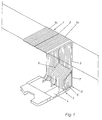
- the transition shown at 3 in FIG. 1 has the bellows 1 with the bellows elements 1a and 1b, the are connected by the middle frame 2.
- the one with The transition designated 3 also has the turntable 4 of the hinge not shown in detail, which the two vehicle parts of an articulated vehicle with each other connects.
- the track joint cover bellows 5 Spurfugenabdeckbalg 5 runs to form a tunnel-like cavity 6 at an angle to the bellows 1.
- Held is the Spurfugenabdeckbalg each end by a Frame 7, which on the frame 8 of the corresponding Vehicle part is attached.
- the frames 7 and 9 are from Basically trained the same. There is a difference only in that the frame 9 is double, so that he can accommodate a track joint bellows 5 on both sides can. Such a double frame is shown in FIG. 2 shown. Since the frame 7, the bellows 5 only on one The frame 7 only has one half of the frame 9.
- the frame 2 is the frame for receiving the bellows 5 with 9th or 7 designated.
- the frame 7 or 9, the approximately U-shaped, points in the area of it Leg 10 on the receiving mouth 11.
- the U-shaped trained receiving mouth 11 has the legs 11a, wherein on the legs facing each other approaches 11b, 11c are arranged.
- the connection profile 12 has at one end a claw 12a with which the connection profile 12 can be attached to the neck 11c.
- connection profile 12 with the Clamp part 12b provided, the teeth 12c to be clamped Includes the joint cover bellows 5.
- the clamping means 13 is for example, one made of rubber or rubber deformable profile in the form of a piping that holds a head 13a has an arrowhead shape. This Keder rubber 13 can be pressed into the receiving mouth if that Connection profile lies in the receiving mouth 11.
- the Connection profile 12 is then fixed in the receiving mouth 11, if the flanks 13b or 13c of the head 13a of the welt rubber 13 in the manner shown in Figure 2 on the connection profile 12 or rest on the approach 11b.
Landscapes
- Engineering & Computer Science (AREA)
- Mechanical Engineering (AREA)
- Life Sciences & Earth Sciences (AREA)
- Wood Science & Technology (AREA)
- Diaphragms And Bellows (AREA)
- Sealing Devices (AREA)
- Pivots And Pivotal Connections (AREA)
- Tents Or Canopies (AREA)
- Connection Of Plates (AREA)
Description
- Fig. 1
- zeigt schematisch die Anordnung des Fugenabdeckbalges im Bereich eines Überganges;
- Fig. 2
- zeigt einen Schnitt gemäß der Linie II-II aus Fig. 1.
Claims (9)
- Vorrichtung zur Abdeckung der Spurfuge zwischen dem Drehteller (4) des Drehgelenks und dem Falten- oder Wellenbalg (1) eines Gelenkfahrzeuges umfassend einen Rahmen (7, 9) zur Aufnahme des Spurfugenabdeckbalges (5),
dadurch gekennzeichnet, daß
der Rahmen (7, 9) ein Aufnahmemaul (11) zur klemmbaren Aufnahme des Endes des Spurfugenabdeckbalges (5) aufweist, wobei am Ende des Spurfugenabdeckbalges (5) ein Anschlußprofil (12) angeordnet ist, das von dem Aufnahmemaul (11) aufnehmbar ist, wobei das Anschlußprofil (12) ein Klammerteil (12b) zur Aufnahme des Endes des Spurfugenabdeckbalges aufweist. - Vorrichtung nach Anspruch 1,
dadurch gekennzeichnet, daß
Klemmmittel (13) zur klemmenden Fixierung (12) des Anschlußprofils (11) im Aufnahmemaul vorgesehen sind. - Vorrichtung nach Anspruch 2,
dadurch gekennzeichnet, daß
das Anschlußprofil (12) in das Aufnahmemaul (11) einhängbar ist. - Vorrichtung nach einem oder mehreren der vorstehenden Ansprüche,
dadurch gekennzeichnet, daß
das Klemmmittel (13) als verformbares Profil ausgebildet ist, das in des Aufnahmemaul (11) unter Fixierung des Anschlußprofiles (12) einpreßbar ist. - Vorrichtung nach Anspruch 4,
dadurch gekennzeichnet, daß
das verformbare Profil (13) einen Kopf (13a) aufweist, der in dar Aufnahmemaul (11) im das Anschlußprofil (12) fixierenden Zustand hineinragt. - Vorrichtung nach Anspruch 5,
dadurch gekennzeichnet, daß
der Kopf (13a) pfeilspitzenförmig ausgebildet ist. - Vorrichtung nach einem oder mehreren der Ansprüche 1 bis 6,
dadurch gekennzeichnet, daß
das verformbare Profil (13) als Kedergummi ausgebildet ist. - Vorrichtung nach einem oder mehreren der Ansprüche 1 bis 7,
dadurch gekennzeichnet, daß
das Aufnahmemaul (11) klauenartig ausgebildet ist. - Vorrichtung nach Anspruch 1,
dadurch gekennzeichnet, daß
das Klammerteil (12b) zur Fixierung des Balges (5) Zähne (12c) aufweist.
Applications Claiming Priority (3)
| Application Number | Priority Date | Filing Date | Title |
|---|---|---|---|
| DE29509204U | 1995-06-03 | ||
| DE29509204U DE29509204U1 (de) | 1995-06-03 | 1995-06-03 | Vorrichtung zur Abdeckung der Spurfuge zwischen dem Drehteller des Drehgelenks und dem Falten- oder Wellenbalg eines Gelenkfahrzeugs |
| PCT/DE1996/000872 WO1996039311A1 (de) | 1995-06-03 | 1996-05-17 | Vorrichtung zur abdeckung der spurfuge zwischen dem drehteller des drehgelenks und dem falten- oder wellenbalg eines gelenkfahrzeugs |
Publications (2)
| Publication Number | Publication Date |
|---|---|
| EP0830262A1 EP0830262A1 (de) | 1998-03-25 |
| EP0830262B1 true EP0830262B1 (de) | 1999-03-24 |
Family
ID=8008944
Family Applications (1)
| Application Number | Title | Priority Date | Filing Date |
|---|---|---|---|
| EP96914087A Expired - Lifetime EP0830262B1 (de) | 1995-06-03 | 1996-05-17 | Vorrichtung zur abdeckung der spurfuge zwischen dem drehteller des drehgelenks und dem falten- oder wellenbalg eines gelenkfahrzeugs |
Country Status (8)
| Country | Link |
|---|---|
| US (1) | US5884565A (de) |
| EP (1) | EP0830262B1 (de) |
| CN (1) | CN1063141C (de) |
| AT (1) | ATE178000T1 (de) |
| DE (2) | DE29509204U1 (de) |
| DK (1) | DK0830262T3 (de) |
| ES (1) | ES2131940T3 (de) |
| WO (1) | WO1996039311A1 (de) |
Cited By (3)
| Publication number | Priority date | Publication date | Assignee | Title |
|---|---|---|---|---|
| EP2159084A1 (de) | 2008-08-22 | 2010-03-03 | HÜBNER GmbH | Übergang zwischen zwei gelenkig miteinander verbundenen Fahrzeugen |
| EP2562014A1 (de) | 2011-08-24 | 2013-02-27 | Hübner GmbH | Balg eines Übergangs zwischen zwei gelenkig miteinander verbundenen Fahrzeugen eines Gelenkfahrzeuges |
| US9233553B2 (en) | 2000-09-11 | 2016-01-12 | Videojet Technologies (Nottingham) Limited | Tape drive and printing apparatus |
Families Citing this family (17)
| Publication number | Priority date | Publication date | Assignee | Title |
|---|---|---|---|---|
| US6694890B2 (en) * | 2001-03-14 | 2004-02-24 | Los Angeles County Metropolitan Transportation Authority | Method and apparatus for providing a between car barrier for transportation vehicles |
| US20040187725A1 (en) * | 2001-03-14 | 2004-09-30 | Los Angeles County Metropolitan Transportation Authority | Method and apparatus for providing a partitioned between-car barrier for transportation vehicles |
| JP4188852B2 (ja) * | 2004-01-28 | 2008-12-03 | 株式会社成田製作所 | 鉄道車両用パネル装置 |
| DE102005032218A1 (de) | 2005-07-09 | 2007-01-11 | Hübner GmbH | Vorrichtung zum Abdecken der Spurfuge (Spurfugenabdeckung) zwischen dem Drehteller und dem Balg eines Übergangs zwischen zwei gelenkig miteinander verbundener Fahrzeugteile |
| CN100387465C (zh) * | 2005-11-01 | 2008-05-14 | 李岭群 | 车厢间密封连接装置 |
| ATE475572T1 (de) * | 2008-03-31 | 2010-08-15 | Atg Autotechnik Gmbh | Faltenbalg |
| IT1390798B1 (it) * | 2008-07-31 | 2011-10-19 | Pei Protezioni Elaborazioni | Dispositivo di collegamento tra il soffietto ed il telaio di veicoli articolati. |
| IT1390797B1 (it) * | 2008-07-31 | 2011-10-19 | Pei Protezioni Elaborazioni | Dispositivo di collegamento tra il soffietto ed il telaio di veicoli articolati. |
| CN101934693B (zh) * | 2010-01-04 | 2013-01-09 | 伊卡路斯(苏州)车辆系统有限公司 | 一种客车铰接棚 |
| US8733777B2 (en) | 2010-02-05 | 2014-05-27 | HÜBNER GmbH & Co. KG | Corrugation bellows of a transfer between two pivotably interconnected vehicles |
| ES2539037T3 (es) * | 2010-02-05 | 2015-06-25 | HÜBNER GmbH & Co. KG | Fuelle ondulado de un paso entre dos vehículos conectados de modo articulado entre ellos |
| EP2386432B1 (de) * | 2010-05-11 | 2013-04-03 | Hübner GmbH | Gelenkfahrzeug |
| DE102013218547B3 (de) * | 2013-09-16 | 2015-02-05 | Bombardier Transportation Gmbh | Übergangsplattform mit Verwindungszonen, Fahrzeuggelenksystem und Schienenfahrzeug |
| CN104626900B (zh) * | 2013-11-08 | 2017-08-04 | 虎伯拉铰接系统(上海)有限公司 | 铰接的车辆部分间过渡部装置的折棚或飞机登机桥的折棚 |
| ITUB20159591A1 (it) * | 2015-12-22 | 2017-06-22 | P E I Protezioni Elaborazioni Ind S R L | Dispositivo e metodo di protezione per veicoli articolati. |
| DE102017102626A1 (de) * | 2017-02-09 | 2018-08-09 | HÜBNER GmbH & Co. KG | Mehrschichtiges Flächengebilde aufweisend zumindest ein Trägergewebe, Übergangselement aufweisend ein derartiges mehrschichtiges Flächengebilde, sowie Fahrzeug, Fluggastbrücke oder -treppe mit einem derartigen Übergangselement |
| PL3495227T3 (pl) * | 2017-12-05 | 2022-02-14 | HÜBNER GmbH & Co. KG | Zespół przejścia między dwoma połączonymi ze sobą ruchomo członami pojazdu |
Family Cites Families (10)
| Publication number | Priority date | Publication date | Assignee | Title |
|---|---|---|---|---|
| US4222605A (en) * | 1976-11-02 | 1980-09-16 | Engelhard Thomas E | Window boot |
| US4257645A (en) * | 1979-01-12 | 1981-03-24 | Schlegel Corporation | Flexible sheet seal |
| US4583523A (en) * | 1984-07-02 | 1986-04-22 | Lloyd & Associates | Implantable heart assist device and method of implanting same |
| FR2629034B1 (fr) * | 1988-03-25 | 1990-04-20 | Caoutchouc Manuf Plastique | Membrane deformable pour tunnel d'intercirculation entre vehicules successifs ferroviaires ou routiers |
| FR2645097B1 (fr) * | 1989-03-28 | 1991-06-21 | Caoutchouc Manuf Plastique | Membrane deformable pour tunnel d'intercirculation entre vehicules successifs ferroviaires ou routiers a ondes de profondeur croissante |
| DE4105449A1 (de) * | 1991-02-21 | 1992-08-27 | Huebner Gummi & Kunststoff | Faltenbalg fuer uebergaenge von gelenkfahrzeugen, halteprofil fuer die befestigung eines solchen faltenbalgs an einem gelenkfahrzeug und bausatz aus einem solchen faltenbalg und einem solchen halteprofil sowie einbauverfahren |
| EP0562598A1 (de) * | 1992-03-25 | 1993-09-29 | HÜBNER Gummi- und Kunststoff GmbH | Gelenkverbindung zwischen zwei gelenkig miteinander verbundenen Fahrzeugen |
| US5280984A (en) * | 1992-10-02 | 1994-01-25 | Paccar Inc. | Walk through boot assembly and method |
| DE9413320U1 (de) * | 1994-08-18 | 1994-11-10 | Hübner Gummi- und Kunststoff GmbH, 34123 Kassel | Faltenbalg |
| DE29500695U1 (de) * | 1995-01-19 | 1995-03-16 | Hübner Gummi- und Kunststoff GmbH, 34123 Kassel | Flexible Verkleidung eines Übergangs |
-
1995
- 1995-06-03 DE DE29509204U patent/DE29509204U1/de not_active Expired - Lifetime
-
1996
- 1996-05-17 AT AT96914087T patent/ATE178000T1/de active
- 1996-05-17 DK DK96914087T patent/DK0830262T3/da active
- 1996-05-17 DE DE59601504T patent/DE59601504D1/de not_active Expired - Lifetime
- 1996-05-17 CN CN96191674A patent/CN1063141C/zh not_active Expired - Lifetime
- 1996-05-17 ES ES96914087T patent/ES2131940T3/es not_active Expired - Lifetime
- 1996-05-17 EP EP96914087A patent/EP0830262B1/de not_active Expired - Lifetime
- 1996-05-17 WO PCT/DE1996/000872 patent/WO1996039311A1/de not_active Ceased
-
1997
- 1997-07-09 US US08/890,474 patent/US5884565A/en not_active Expired - Lifetime
Cited By (4)
| Publication number | Priority date | Publication date | Assignee | Title |
|---|---|---|---|---|
| US9233553B2 (en) | 2000-09-11 | 2016-01-12 | Videojet Technologies (Nottingham) Limited | Tape drive and printing apparatus |
| EP2159084A1 (de) | 2008-08-22 | 2010-03-03 | HÜBNER GmbH | Übergang zwischen zwei gelenkig miteinander verbundenen Fahrzeugen |
| EP2562014A1 (de) | 2011-08-24 | 2013-02-27 | Hübner GmbH | Balg eines Übergangs zwischen zwei gelenkig miteinander verbundenen Fahrzeugen eines Gelenkfahrzeuges |
| RU2527588C2 (ru) * | 2011-08-24 | 2014-09-10 | ХЮБНЕР ГмбХ | Сильфонное уплотнение перехода между двумя соединенными друг с другом шарнирами сочленённого транспортного средства |
Also Published As
| Publication number | Publication date |
|---|---|
| WO1996039311A1 (de) | 1996-12-12 |
| DE29509204U1 (de) | 1995-09-28 |
| DK0830262T3 (da) | 1999-05-25 |
| ES2131940T3 (es) | 1999-08-01 |
| CN1063141C (zh) | 2001-03-14 |
| EP0830262A1 (de) | 1998-03-25 |
| DE59601504D1 (de) | 1999-04-29 |
| CN1169700A (zh) | 1998-01-07 |
| US5884565A (en) | 1999-03-23 |
| ATE178000T1 (de) | 1999-04-15 |
Similar Documents
| Publication | Publication Date | Title |
|---|---|---|
| EP0830262B1 (de) | Vorrichtung zur abdeckung der spurfuge zwischen dem drehteller des drehgelenks und dem falten- oder wellenbalg eines gelenkfahrzeugs | |
| DE4210456C2 (de) | Querverbindung für Profilstäbe mittels Zuggliedern | |
| DE4223898A1 (de) | Dachreling für Fahrzeuge | |
| DE3248148C2 (de) | Klemmhülse | |
| DE19641500A1 (de) | Vorrichtung zum lösbaren Verbinden von Profilstäben | |
| EP0619091B1 (de) | Haltestange zum Halten und/oder Aussteifen von Trennwänden für Duschkabinen | |
| DE10143607A1 (de) | Vorrichtung zur Befestigung eines Anbauteiles | |
| EP1580343B1 (de) | Stossverbinder zur Verbindung von Profilen | |
| DE2656958A1 (de) | Eckverbindung von auf gehrung geschnittenen profilen | |
| DE19818597C1 (de) | Verbindungselement | |
| DE3106794C2 (de) | Kabelschelle | |
| DE19513623A1 (de) | Hohlprofil-Metallgerüst | |
| DE6804291U (de) | Zarge fuer turen- bzw. fenster | |
| DE29508427U1 (de) | Anordnung zur Befestigung einer Fensterscheibe in einem flexiblen Verdeck o.dgl. | |
| DE9014882U1 (de) | Einrichtung für die Befestigung eines Tragarms an einer Tischplatte | |
| DE2601390A1 (de) | Eckumlenkung fuer treibstangenbeschlaege von fenstern, tueren o.dgl. | |
| DE19758276A1 (de) | Vorrichtung für Betonschalungen | |
| DE29703868U1 (de) | Montage-Hilfsrahmen für Fensteranschlußrahmen | |
| DE20021190U1 (de) | Anordnung aus einem Verkleidungsteil und einem Dichtungsprofil | |
| DE2614082B2 (de) | Fenster mit einem Flügelrahmen aus vier winkelförmigen, um die Scheibe herum zusammengesetzten Rahmenteilen | |
| DE2918175C3 (de) | Verbolzung für im Untertagebetrieb verwendete Ausbaurahmen | |
| EP0755838B1 (de) | Gerippestruktur mit Türrahmen und Wandelementen | |
| DE3010899C2 (de) | Verbolzung für im Untertagebetrieb verwendete Ausbaurahmen | |
| EP0264058B1 (de) | Kastenkonstruktion, insbesondere für Nutzfahrzeuge wie beispielsweise Brandschutzfahrzeuge | |
| DE19633739C2 (de) | Am Mast zu befestigendes Anzeigemodul für Haltestellen oder dergleichen |
Legal Events
| Date | Code | Title | Description |
|---|---|---|---|
| PUAI | Public reference made under article 153(3) epc to a published international application that has entered the european phase |
Free format text: ORIGINAL CODE: 0009012 |
|
| 17P | Request for examination filed |
Effective date: 19970715 |
|
| AK | Designated contracting states |
Kind code of ref document: A1 Designated state(s): AT BE CH DE DK ES FI FR GB IT LI NL PT SE |
|
| GRAG | Despatch of communication of intention to grant |
Free format text: ORIGINAL CODE: EPIDOS AGRA |
|
| GRAG | Despatch of communication of intention to grant |
Free format text: ORIGINAL CODE: EPIDOS AGRA |
|
| GRAH | Despatch of communication of intention to grant a patent |
Free format text: ORIGINAL CODE: EPIDOS IGRA |
|
| 17Q | First examination report despatched |
Effective date: 19980828 |
|
| GRAH | Despatch of communication of intention to grant a patent |
Free format text: ORIGINAL CODE: EPIDOS IGRA |
|
| GRAA | (expected) grant |
Free format text: ORIGINAL CODE: 0009210 |
|
| AK | Designated contracting states |
Kind code of ref document: B1 Designated state(s): AT BE CH DE DK ES FI FR GB IT LI NL PT SE |
|
| REF | Corresponds to: |
Ref document number: 178000 Country of ref document: AT Date of ref document: 19990415 Kind code of ref document: T |
|
| REG | Reference to a national code |
Ref country code: CH Ref legal event code: EP |
|
| REG | Reference to a national code |
Ref country code: CH Ref legal event code: NV Representative=s name: CABINET ROLAND NITHARDT CONSEILS EN PROPRIETE INDU |
|
| GBT | Gb: translation of ep patent filed (gb section 77(6)(a)/1977) |
Effective date: 19990325 |
|
| REF | Corresponds to: |
Ref document number: 59601504 Country of ref document: DE Date of ref document: 19990429 |
|
| ET | Fr: translation filed | ||
| REG | Reference to a national code |
Ref country code: DK Ref legal event code: T3 |
|
| REG | Reference to a national code |
Ref country code: PT Ref legal event code: SC4A Free format text: AVAILABILITY OF NATIONAL TRANSLATION Effective date: 19990325 |
|
| REG | Reference to a national code |
Ref country code: ES Ref legal event code: FG2A Ref document number: 2131940 Country of ref document: ES Kind code of ref document: T3 |
|
| PLBE | No opposition filed within time limit |
Free format text: ORIGINAL CODE: 0009261 |
|
| STAA | Information on the status of an ep patent application or granted ep patent |
Free format text: STATUS: NO OPPOSITION FILED WITHIN TIME LIMIT |
|
| 26N | No opposition filed | ||
| REG | Reference to a national code |
Ref country code: GB Ref legal event code: IF02 |
|
| REG | Reference to a national code |
Ref country code: CH Ref legal event code: PCAR Free format text: CABINET ROLAND NITHARDT CONSEILS EN PROPRIETE INDUSTRIELLE S.A.;Y-PARC RUE GALILEE;1400 YVERDON-LES-BAINS (CH) |
|
| PGFP | Annual fee paid to national office [announced via postgrant information from national office to epo] |
Ref country code: FI Payment date: 20110512 Year of fee payment: 16 Ref country code: DK Payment date: 20110512 Year of fee payment: 16 |
|
| REG | Reference to a national code |
Ref country code: DK Ref legal event code: EBP |
|
| PG25 | Lapsed in a contracting state [announced via postgrant information from national office to epo] |
Ref country code: FI Free format text: LAPSE BECAUSE OF NON-PAYMENT OF DUE FEES Effective date: 20120517 |
|
| PG25 | Lapsed in a contracting state [announced via postgrant information from national office to epo] |
Ref country code: DK Free format text: LAPSE BECAUSE OF NON-PAYMENT OF DUE FEES Effective date: 20120531 |
|
| PGFP | Annual fee paid to national office [announced via postgrant information from national office to epo] |
Ref country code: GB Payment date: 20130521 Year of fee payment: 18 |
|
| PGFP | Annual fee paid to national office [announced via postgrant information from national office to epo] |
Ref country code: NL Payment date: 20130521 Year of fee payment: 18 Ref country code: PT Payment date: 20130516 Year of fee payment: 18 |
|
| REG | Reference to a national code |
Ref country code: PT Ref legal event code: MM4A Free format text: LAPSE DUE TO NON-PAYMENT OF FEES Effective date: 20141117 |
|
| REG | Reference to a national code |
Ref country code: NL Ref legal event code: V1 Effective date: 20141201 |
|
| GBPC | Gb: european patent ceased through non-payment of renewal fee |
Effective date: 20140517 |
|
| PG25 | Lapsed in a contracting state [announced via postgrant information from national office to epo] |
Ref country code: PT Free format text: LAPSE BECAUSE OF NON-PAYMENT OF DUE FEES Effective date: 20141117 |
|
| PG25 | Lapsed in a contracting state [announced via postgrant information from national office to epo] |
Ref country code: NL Free format text: LAPSE BECAUSE OF NON-PAYMENT OF DUE FEES Effective date: 20141201 |
|
| REG | Reference to a national code |
Ref country code: FR Ref legal event code: PLFP Year of fee payment: 20 |
|
| PG25 | Lapsed in a contracting state [announced via postgrant information from national office to epo] |
Ref country code: GB Free format text: LAPSE BECAUSE OF NON-PAYMENT OF DUE FEES Effective date: 20140517 |
|
| PGFP | Annual fee paid to national office [announced via postgrant information from national office to epo] |
Ref country code: DE Payment date: 20150401 Year of fee payment: 20 Ref country code: SE Payment date: 20150520 Year of fee payment: 20 Ref country code: CH Payment date: 20150521 Year of fee payment: 20 Ref country code: ES Payment date: 20150527 Year of fee payment: 20 |
|
| PGFP | Annual fee paid to national office [announced via postgrant information from national office to epo] |
Ref country code: IT Payment date: 20150515 Year of fee payment: 20 Ref country code: BE Payment date: 20150520 Year of fee payment: 20 Ref country code: FR Payment date: 20150521 Year of fee payment: 20 Ref country code: AT Payment date: 20150521 Year of fee payment: 20 |
|
| REG | Reference to a national code |
Ref country code: DE Ref legal event code: R071 Ref document number: 59601504 Country of ref document: DE |
|
| REG | Reference to a national code |
Ref country code: CH Ref legal event code: PL |
|
| REG | Reference to a national code |
Ref country code: AT Ref legal event code: MK07 Ref document number: 178000 Country of ref document: AT Kind code of ref document: T Effective date: 20160517 |
|
| REG | Reference to a national code |
Ref country code: ES Ref legal event code: FD2A Effective date: 20160826 |
|
| PG25 | Lapsed in a contracting state [announced via postgrant information from national office to epo] |
Ref country code: ES Free format text: LAPSE BECAUSE OF EXPIRATION OF PROTECTION Effective date: 20160518 |