EP0830262B1 - Fixture for covering the track joint between the rotary plate of the swivel joint and the bellows or concertina walls of an articulated vehicle - Google Patents
Fixture for covering the track joint between the rotary plate of the swivel joint and the bellows or concertina walls of an articulated vehicle Download PDFInfo
- Publication number
- EP0830262B1 EP0830262B1 EP96914087A EP96914087A EP0830262B1 EP 0830262 B1 EP0830262 B1 EP 0830262B1 EP 96914087 A EP96914087 A EP 96914087A EP 96914087 A EP96914087 A EP 96914087A EP 0830262 B1 EP0830262 B1 EP 0830262B1
- Authority
- EP
- European Patent Office
- Prior art keywords
- bellows
- joint
- covering
- profile
- receiving mouth
- Prior art date
- Legal status (The legal status is an assumption and is not a legal conclusion. Google has not performed a legal analysis and makes no representation as to the accuracy of the status listed.)
- Expired - Lifetime
Links
Images

Classifications
-
- B—PERFORMING OPERATIONS; TRANSPORTING
- B60—VEHICLES IN GENERAL
- B60D—VEHICLE CONNECTIONS
- B60D5/00—Gangways for coupled vehicles, e.g. of concertina type
- B60D5/003—Bellows for interconnecting vehicle parts
-
- B—PERFORMING OPERATIONS; TRANSPORTING
- B60—VEHICLES IN GENERAL
- B60D—VEHICLE CONNECTIONS
- B60D5/00—Gangways for coupled vehicles, e.g. of concertina type
- B60D5/006—Passages between articulated vehicles, e.g. bridges or rotating plates
-
- B—PERFORMING OPERATIONS; TRANSPORTING
- B61—RAILWAYS
- B61D—BODY DETAILS OR KINDS OF RAILWAY VEHICLES
- B61D17/00—Construction details of vehicle bodies
- B61D17/04—Construction details of vehicle bodies with bodies of metal; with composite, e.g. metal and wood body structures
- B61D17/20—Communication passages between coaches; Adaptation of coach ends therefor
Definitions
- the invention relates to a device for covering the Track between the turntable of the swivel and the Bellows or bellows of a gel vehicle, comprising a frame for holding a track joint cover bellows, according to the features of the preamble of claim 1.
- a device for covering the Track between the turntable of the swivel and the Bellows or bellows of a gel vehicle comprising a frame for holding a track joint cover bellows, according to the features of the preamble of claim 1.
- the Spurugenabdeckbalg runs to form a tunnel-like cavity parallel to the central longitudinal axis of a Articulated vehicle angled to bellows or bellows.
- the Spurfugenabedeckbalg does not only have the task of the track joint between the turntable and bellows or corrugated bellows. but also offers the possibility that in the tunnel-like formed by the track bellows Cavity also supply lines between the one and the other part of the car can be guided.
- the invention is therefore based on the object Device for covering the track joint between the Turntable of a swivel and the bellows or bellows to create an articulated vehicle that uses Bellows of different lengths allowed without the Bellows by attaching any fixative must be assembled in advance.
- the Frame a recording mouth for the clampable recording of the end of the Spurfugenabdeckbalges has, at the end of Spurfugenabdeckbalges a connection profile is arranged that is recordable from the receiving mouth, the Connection profile a bracket part for receiving the end of the Has track joint cover bellows.
- the Bellows can be manufactured by the meter, and accordingly the desired length can be cut off, then with With the help of the clamp part of the connection profile be through an appropriate recording in the form of a Recording mouth is recordable.
- a special packaging the bellows is no longer required. This can such a Spurfugenabdeckbalg much cheaper are produced, as this in particular according to the state of the Technology according to US Pat. No. 5,280,984 is the case.
- Advantageous has the clamp part for fixing the bellows teeth.
- the Clamping means for clamping fixation of the Connection profile provided in the mouth.
- the assembly or Disassembly of the device is made even easier. that the connecting profile can be hooked into the receiving mouth.
- the Clamping means is preferably a deformable profile, for example made of rubber or Rubber formed and fixed in the receiving mouth of the connection profile can be pressed in. Specifically, this indicates Profile a head on that in the receiving mouth in the Connection profile fixing state protrudes. To do with that It is better to push the headed profile into the receiving mouth the head of the profile is arrowhead-shaped shaped. To fix the connection profile and the arrowhead-shaped head of the deformable Profile the mouth is claw-like. That is, that the receiving profile has a U-shape in cross section, wherein the legs have approaches to face each other. At these approaches, the profile head is inserted Supporting condition from the inside.
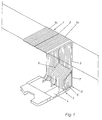
- the transition shown at 3 in FIG. 1 has the bellows 1 with the bellows elements 1a and 1b, the are connected by the middle frame 2.
- the one with The transition designated 3 also has the turntable 4 of the hinge not shown in detail, which the two vehicle parts of an articulated vehicle with each other connects.
- the track joint cover bellows 5 Spurfugenabdeckbalg 5 runs to form a tunnel-like cavity 6 at an angle to the bellows 1.
- Held is the Spurfugenabdeckbalg each end by a Frame 7, which on the frame 8 of the corresponding Vehicle part is attached.
- the frames 7 and 9 are from Basically trained the same. There is a difference only in that the frame 9 is double, so that he can accommodate a track joint bellows 5 on both sides can. Such a double frame is shown in FIG. 2 shown. Since the frame 7, the bellows 5 only on one The frame 7 only has one half of the frame 9.
- the frame 2 is the frame for receiving the bellows 5 with 9th or 7 designated.
- the frame 7 or 9, the approximately U-shaped, points in the area of it Leg 10 on the receiving mouth 11.
- the U-shaped trained receiving mouth 11 has the legs 11a, wherein on the legs facing each other approaches 11b, 11c are arranged.
- the connection profile 12 has at one end a claw 12a with which the connection profile 12 can be attached to the neck 11c.
- connection profile 12 with the Clamp part 12b provided, the teeth 12c to be clamped Includes the joint cover bellows 5.
- the clamping means 13 is for example, one made of rubber or rubber deformable profile in the form of a piping that holds a head 13a has an arrowhead shape. This Keder rubber 13 can be pressed into the receiving mouth if that Connection profile lies in the receiving mouth 11.
- the Connection profile 12 is then fixed in the receiving mouth 11, if the flanks 13b or 13c of the head 13a of the welt rubber 13 in the manner shown in Figure 2 on the connection profile 12 or rest on the approach 11b.
Landscapes
- Engineering & Computer Science (AREA)
- Mechanical Engineering (AREA)
- Life Sciences & Earth Sciences (AREA)
- Wood Science & Technology (AREA)
- Diaphragms And Bellows (AREA)
- Sealing Devices (AREA)
- Tents Or Canopies (AREA)
- Pivots And Pivotal Connections (AREA)
- Connection Of Plates (AREA)
Abstract
Description
Die Erfindung betrifft eine Vorrichtung zur Abdeckung der
Spurfuge zwischen dem Drehteller des Drehgelenks und dem
Falten- oder Wellenbalg eines Gelekfahrzeugs, umfassend
einen Rahmen zur Aufnahme eines Spurfugenabdeckbalges,
gemäß den Merkmalen des Oberbegriffes von Anspruch 1.
Der
Spurfugenabdeckbalg verläuft unter Bildung eines
tunnelartigen Hohlraumes parallel zur Mittellängsachse eines
Gelenkfahrzeugs abgewinkelt zum Falten- oder Wellenbalg. Der
Spurfugenabedeckbalg hat nicht nur die Aufgabe die Spurfuge
zwischen Drehteller und Falten- oder Wellenbalg abzudecken.
sondern bietet darüber hinaus die Möglichkeit, daß in dem
durch den Spurfugenabdeckbalg gebildeten tunnelartige
Hohlraum auch Versorgungsleitungen zwischen dem einen und dem
anderen Wagenteil geführt werden können. The invention relates to a device for covering the
Track between the turntable of the swivel and the
Bellows or bellows of a gel vehicle, comprising
a frame for holding a track joint cover bellows,
according to the features of the preamble of
Damit die Versorgungsleitungen zugänglich sind, ist es erforderlich, daß der Spurfugenabdeckbalg abnehmbar ist. Hierzu ist nach dem Stand der Technik eine Verbindung zwischen Rahmen und Fugenabdeckbalg vorgesehen, die sich im einzelnen dadurch auszeichnet, daß der Rahmen und der Spurfugenabdeckbalg Bohrungen aufweist, wobei durch die Bohrungen Drehverschlüsse hindurchragen, wobei durch die Drehverschlüsse der Faltenbalg formschlüssig an dem Rahmen fixierbar ist. Diese Verbindung zwischen dem Spurfugenabdeckbalg und dem Rahmen ist überaus aufwendig und damit teuer in der Herstellung. Darüber hinaus treten auch fertigungstechnische Probleme auf, die daraus resultieren, daß die Bohrungen des Faltenbalges und die des Rahmens nicht immer fluchtend zueinander angeordnet sind, so daß der Drehverschluß nicht durch die entsprechenden Bohrung hindurchführbar ist.So that the supply lines are accessible, it is necessary that the track joint cover is removable is. There is a connection for this in accordance with the prior art provided between the frame and joint cover bellows, which are in characterized in that the frame and the Spurfugenabdeckbalg has holes, whereby through the Holes protrude from screw caps, whereby through the Twist locks of the bellows form-fitting on the frame is fixable. This connection between the Spurfugenabdeckbalg and the frame is extremely complex and therefore expensive to manufacture. Beyond that, too manufacturing problems that result from that the bores of the bellows and that of the frame are not are always aligned with each other so that the Turn lock not through the corresponding hole can be passed through.
Aus der US-PS 4,257,645 ist keine Vorrichtung zum Abdecken der Spurfuge zwischen dem Drehteller des Drehgelenks und dem Falten- oder Wellenbalg eines Gelenkfahrzeuges bekannt, sondern vielmehr eine luft- und wasserdichte Verbindung in Form einer balgartigen aufblasbaren Ringröhre. Darüber hinaus ist bei dem Balg gemäß dieser US-Patentschrift eine Konfektionierung erforderlich, die im vorliegenden Fall darin besteht, daß ein Klemmelement an dem Balg stoffschlüssig angebracht wird.No device for covering is known from US Pat. No. 4,257,645 the track joint between the turntable of the swivel and the Bellows or bellows of an articulated vehicle known, but rather an airtight and watertight connection in Form of a bellows-like inflatable ring tube. Furthermore is a in the bellows according to this US patent Packaging required in this case there is a clamping element on the bellows cohesively is attached.
Aus der US-PS 5,280,984 nächstliegender Stand der Technik ist ein Faltenbalg zur Verbindung zweier Fahrzeugteile bekannt. Endseitig besitzt ein derartiger Faltenbalg ein Rückhalteglied, das von einer entsprechenden Ausnehmung in den beiden Wagenteilen, die durch den Faltenbalg verbunden sind, klemmend aufnehmbar ist. Nachteilig bei dieser Gestaltung eines Faltenbalges ist, daß der Faltenbalg auch hier immer speziell konfektioniert sein muß. Das heißt, daß die Halteelemente, die endseitig an dem Faltenbalg angeordnet sind, immer gesondert an den Faltenbalg angebracht werden müssen. Es ist demzufolge im eigentlichen Sinne eine Serienfertigung nicht möglich. Dies insbesondere vor dem Hintergrund, daß gegebenenfalls Faltenbälge unterschiedlicher Länge eingesetzt werden müssen. From U.S. Patent 5,280,984 closest state of the art is a bellows for connection two vehicle parts known. End has a such a bellows a retaining member that a corresponding recess in the two car parts, the are connected by the bellows, is clamped. A disadvantage of this design of a bellows is that the bellows must always be specially assembled got to. This means that the holding elements, the end of the Bellows are arranged, always separately on the bellows must be attached. It is therefore, in fact Series production not possible. This in particular against the background that any bellows different lengths must be used.
Der Erfindung liegt daher die Aufgabe zugrunde, eine Vorrichtung zur Abdeckung der Spurfuge zwischen dem Drehteller eines Drehgelenkes und dem Falten- oder Wellenbalg eines Gelenkfahrzeuges zu schaffen, der den Einsatz von Faltenbälgen unterschiedlicher Länge erlaubt, ohne daß der Faltenbalg durch Anbringung von irgendwelchen Fixiermitteln vorab konfektioniert werden muß.The invention is therefore based on the object Device for covering the track joint between the Turntable of a swivel and the bellows or bellows to create an articulated vehicle that uses Bellows of different lengths allowed without the Bellows by attaching any fixative must be assembled in advance.
Die Aufgabe wird erfindungsgemäß dadurch gelöst, daß der Rahmen ein Aufnahmemaul zur klemmbaren Aufnahme des Endes des Spurfugenabdeckbalges aufweist, wobei am Ende des Spurfugenabdeckbalges ein Anschlußprofil angeordnet ist, daß von dem Aufnahmemaul aufnehmbar ist, wobei das Anschlußpropfil ein Klammerteil zur Aufnahme des Endes des Spurfugenabdeckbalges aufweist.The object is achieved in that the Frame a recording mouth for the clampable recording of the end of the Spurfugenabdeckbalges has, at the end of Spurfugenabdeckbalges a connection profile is arranged that is recordable from the receiving mouth, the Connection profile a bracket part for receiving the end of the Has track joint cover bellows.
Mit einer derartigen Vorrichtung wird nun erreicht, daß der Faltenbalg als Meterware herstellbar ist, und entsprechend der gewünschten Länge abgeschnitten werden kann, um dann mit Hilfe des Klammerteiles des Anschlußprofiles erfaßt zu werden, das durch eine entsprechende Aufnahme in Form eines Aufnahmemauls aufnehmbar ist. Eine besondere Konfektionierung des Balges ist somit nicht mehr erforderlich. Hierdurch kann ein derartiger Spurfugenabdeckbalg wesentlich günstiger hergestellt werden, als dies insbesondere nach dem Stand der Technik gemäß der US-PS 5,280,984 der Fall ist. Vorteilhaft besitzt das Klammerteil zur Fixierung des Balges Zähne.With such a device it is now achieved that the Bellows can be manufactured by the meter, and accordingly the desired length can be cut off, then with With the help of the clamp part of the connection profile be through an appropriate recording in the form of a Recording mouth is recordable. A special packaging the bellows is no longer required. This can such a Spurfugenabdeckbalg much cheaper are produced, as this in particular according to the state of the Technology according to US Pat. No. 5,280,984 is the case. Advantageous has the clamp part for fixing the bellows teeth.
Vorteilhaft sind Klemmittel zur klemmenden Fixierung des Anschlußprofils im Aufnahmemaul vorgesehen. Die Montage bzw. Demontage der Vorrichtung wird noch dadurch erleichtert. daß das Anschlußprofil in das Aufnahmemaul einhängbar ist. Das Klemmittel ist vorzugsweise als verformbares Profil, beispielsweise aus Gummi oder Kautschuk ausgebildet und in das Aufnahmemaul unter Fixierung des Anschlußprofiles einpreßbar. Im einzelnen weist das Profil einen Kopf auf, der in das Aufnahmemaul im das Anschlußprofil fixierenden Zustand hineinragt. Um das mit dem Kopf versehene Profil besser in das Aufnahmemaul einschieben zu können, ist der Kopf des Profils pfeilspitzenförmig geformt. Zur Fixierung des Anschlußprofils und des pfeilspitzenförmig ausgebildeten Kopfes des verformbaren Profils ist das Aufnehmemaul klauenartig ausgebildet. D. h., daß das Aufnahmeprofil im Querschnitt eine U-Form aufweist, wobei die Schenkel aufeinander zu weisende Ansätze aufweisen. An diesen Ansätzen liegt der Profilkopf im eingeschobenen Zustand von innen sich abstützend an.Clamping means for clamping fixation of the Connection profile provided in the mouth. The assembly or Disassembly of the device is made even easier. that the connecting profile can be hooked into the receiving mouth. The Clamping means is preferably a deformable profile, for example made of rubber or Rubber formed and fixed in the receiving mouth of the connection profile can be pressed in. Specifically, this indicates Profile a head on that in the receiving mouth in the Connection profile fixing state protrudes. To do with that It is better to push the headed profile into the receiving mouth the head of the profile is arrowhead-shaped shaped. To fix the connection profile and the arrowhead-shaped head of the deformable Profile the mouth is claw-like. That is, that the receiving profile has a U-shape in cross section, wherein the legs have approaches to face each other. At these approaches, the profile head is inserted Supporting condition from the inside.
Anhand der Zeichnung wird die Erfindung nachstehend beispielaft näher erläutert.
- Fig. 1
- zeigt schematisch die Anordnung des Fugenabdeckbalges im Bereich eines Überganges;
- Fig. 2
- zeigt einen Schnitt gemäß der Linie II-II aus Fig. 1.
- Fig. 1
- shows schematically the arrangement of the joint cover bellows in the region of a transition;
- Fig. 2
- shows a section along the line II-II of Fig. 1st
Der in Fig. 1 dargestellte mit 3 bezeichnete Übergang besitzt
den Faltenbalg 1 mit den Faltenbalgelementen 1a und 1b, die
durch den Mittelrahmen 2 miteinander verbunden sind. Der mit
3 bezeichnete Übergang weist darüber hinaus den Drehteller 4
des nicht im einzelnen dargestellten Drehgelenks auf, das die
beiden Fahrzeugteile eines Gelenkfahrzeugs miteinander
verbindet. Im Bereich des Spaltes zwischen Drehteller und
Faltenbalg 1 befindet sich der Spurfugenabdeckbalg 5. Der
Spurfugenabdeckbalg 5 verläuft unter Bildung eines
tunnelartigen Hohlraumes 6 winklig zum Faltenbalg 1. Gehalten
wird der Spurfugenabdeckbalg endseitig jeweils durch einen
Rahmen 7, der an dem Rahmen 8 des entsprechenden
Fahrzeugteiles befestigt ist. The transition shown at 3 in FIG. 1 has
the
Im Bereich des Mittelrahmens 2 wird der Spurfugenabdeckbalg 5
durch einen weiteren Rahmen 9 gehalten, der mit dem
Mittelrahmen verbunden ist. Die Rahmen 7 und 9 sind vom
Grundsatz her gleich ausgebildet. Ein Unterschied besteht
lediglich darin, daß der Rahmen 9 doppelt ausgebildet ist, so
daß er zu beiden Seiten einen Spurfugenabdeckbalg 5 aufnehmen
kann. Ein derartiger doppelter Rahmen ist in Fig. 2
dargestellt. Da der Rahmen 7 den Faltenbalg 5 nur an einer
Seite aufnehmen muß, stellt der Rahmen 7 nur die eine Hälfte
des Rahmens 9 dar.In the area of the
Gemäß Fig. 2 ist der Rahmen zur Aufnahme des Balges 5 mit 9
bzw. 7 bezeichnet. Der Rahmen 7 bzw. 9, der etwa
U-profilartig ausgebildet ist, weist im Bereich seiner
Schenkel 10 das Aufnahmemaul 11 auf. Das U-förmig
ausgebildete Aufnahmemaul 11 besitzt die Schenkel 11a, wobei
an den Schenkeln endseitig aufeinander zuweisende Ansätze
11b, 11c angeordnet sind. Das Anschlußprofil 12 besitzt an
seinem einen Ende eine Kralle 12a, mit der das Anschlußprofil
12 an den Ansatz 11c einhängbar ist.2 is the frame for receiving the
Am anderen Ende ist das Anschlußprofil 12 mit dem
Klammerteil 12b versehen, das Zähne 12c zur klemmbaren
Aufnahme des Fugenabdeckbalges 5 aufweist. Zur Fixierung des
Anschlußprofiles 12 in dem Aufnahmemaul 11 ist das mit 13
bezeichnete Klemmittel vorgesehen. Das Klemmittel 13 ist
beispielsweise ein aus Gummi oder Kautschuk hergestelltes
verformbares Profil in Form eines Kedergummis, das einen Kopf
13a besitzt, der pfeilspitzenförmig ausgebildet ist. Dieses
Kedergummi 13 ist in das Aufnahmemaul einpreßbar, wenn das
Anschlußprofil in dem Aufnahmemaul 11 einliegt. Das
Anschlußprofil 12 ist dann in dem Aufnahmemaul 11 fixiert,
wenn die Flanken 13b bzw. 13c des Kopfes 13a des Kedergummis
13 in der in Figur 2 dargestellen Weise an dem Anschlußprofil
12 bzw. an dem Ansatz 11b anliegen.At the other end is the
Um das Einpressen des Kopfes 13a des Profiles 13 zu
erleichtern, ist das Profil im Bereich des Kopfes 13a mit
einem Hohlraum 14 versehen, der das Zusammenquetschen beim
Einführen des Kedergummis in das Aufnahmemaul erleichtert.To press the
Claims (9)
- Device for covering the track joint between the rotary plate (4) of the swivel joint and the expansion or concertina bellows (1) of an articulated vehicle comprising a frame (7, 9) to hold the track joint covering bellows (5),
characterized in that
the frame (7, 9) has a receiving mouth (11) for clamping reception of the end of the joint covering bellows (5), whereas the end of the track joint covering bellows (5) comprises a connecting profile (12), which is receivable by the receiving mouth (11), whereas the connecting profile (12) comprises a clamping part (12b) for receiving the end of the joint track covering bellows. - Device according to claim 1,
characterized in that
clamping means (13) being provided in the receiving mouth (11) for a clamping attachment of the connecting profile (12). - Device according to claim 2,
characterized in that
the connecting profile (12) is hungable into the receiving mouth (11). - Device according to one or more of the above-mentioned claims,
characterized in that
the clamping means (13) is designed as a deformable profile that is pressable into the receiving mouth (11) by fastening the connecting profile (12). - Device according to claim 4,
characterized in that
the deformable profile (13) has a head (13a) protruding into the receiving mouth (11) while fixing the connecting profile (12). - Device according to claim 5,
characterized in that
the head (13a) is shaped arrowhead like. - Device according to one or more of the claims 1 to 6,
characterized in that
the deformable profile (13) is designed as a border strengthening rubber. - Device according to one or more of the claims 1 to 7,
characterized in that
the receiving mouth (11) is designed claw like. - Fixture according to claim 1,
characterized in that
the clamping part (12b) is provided with teeth (12c) for fastening the bellows (5).
Applications Claiming Priority (3)
| Application Number | Priority Date | Filing Date | Title |
|---|---|---|---|
| DE29509204U | 1995-06-03 | ||
| DE29509204U DE29509204U1 (en) | 1995-06-03 | 1995-06-03 | Device for covering the track joint between the turntable of the swivel joint and the bellows or bellows of an articulated vehicle |
| PCT/DE1996/000872 WO1996039311A1 (en) | 1995-06-03 | 1996-05-17 | Fixture for covering the track joint between the rotary plate of the swivel joint and the bellows or concertina walls of an articulated vehicle |
Publications (2)
| Publication Number | Publication Date |
|---|---|
| EP0830262A1 EP0830262A1 (en) | 1998-03-25 |
| EP0830262B1 true EP0830262B1 (en) | 1999-03-24 |
Family
ID=8008944
Family Applications (1)
| Application Number | Title | Priority Date | Filing Date |
|---|---|---|---|
| EP96914087A Expired - Lifetime EP0830262B1 (en) | 1995-06-03 | 1996-05-17 | Fixture for covering the track joint between the rotary plate of the swivel joint and the bellows or concertina walls of an articulated vehicle |
Country Status (8)
| Country | Link |
|---|---|
| US (1) | US5884565A (en) |
| EP (1) | EP0830262B1 (en) |
| CN (1) | CN1063141C (en) |
| AT (1) | ATE178000T1 (en) |
| DE (2) | DE29509204U1 (en) |
| DK (1) | DK0830262T3 (en) |
| ES (1) | ES2131940T3 (en) |
| WO (1) | WO1996039311A1 (en) |
Cited By (3)
| Publication number | Priority date | Publication date | Assignee | Title |
|---|---|---|---|---|
| EP2159084A1 (en) | 2008-08-22 | 2010-03-03 | HÜBNER GmbH | Connection between two vehicles with jointed couplings |
| EP2562014A1 (en) | 2011-08-24 | 2013-02-27 | Hübner GmbH | Bellows of an intersection between two vehicles of an articulated vehicle with a jointed connection |
| US9233553B2 (en) | 2000-09-11 | 2016-01-12 | Videojet Technologies (Nottingham) Limited | Tape drive and printing apparatus |
Families Citing this family (17)
| Publication number | Priority date | Publication date | Assignee | Title |
|---|---|---|---|---|
| US20040187725A1 (en) * | 2001-03-14 | 2004-09-30 | Los Angeles County Metropolitan Transportation Authority | Method and apparatus for providing a partitioned between-car barrier for transportation vehicles |
| US6694890B2 (en) * | 2001-03-14 | 2004-02-24 | Los Angeles County Metropolitan Transportation Authority | Method and apparatus for providing a between car barrier for transportation vehicles |
| JP4188852B2 (en) * | 2004-01-28 | 2008-12-03 | 株式会社成田製作所 | Railcar panel equipment |
| DE102005032218A1 (en) * | 2005-07-09 | 2007-01-11 | Hübner GmbH | Device for covering the gap joint (Spurfugenabdeckung) between the turntable and the bellows of a transition between two articulated vehicle parts |
| CN100387465C (en) * | 2005-11-01 | 2008-05-14 | 李岭群 | Tight connection equipment between carriages |
| ATE475572T1 (en) * | 2008-03-31 | 2010-08-15 | Atg Autotechnik Gmbh | BELLOWS |
| IT1390797B1 (en) * | 2008-07-31 | 2011-10-19 | Pei Protezioni Elaborazioni | CONNECTION DEVICE BETWEEN THE BELLOWS AND THE FRAME OF ARTICULATED VEHICLES. |
| IT1390798B1 (en) * | 2008-07-31 | 2011-10-19 | Pei Protezioni Elaborazioni | CONNECTION DEVICE BETWEEN THE BELLOWS AND THE FRAME OF ARTICULATED VEHICLES. |
| CN101934693B (en) * | 2010-01-04 | 2013-01-09 | 伊卡路斯(苏州)车辆系统有限公司 | Hinged shack for coach |
| US8733777B2 (en) | 2010-02-05 | 2014-05-27 | HÜBNER GmbH & Co. KG | Corrugation bellows of a transfer between two pivotably interconnected vehicles |
| PL2353894T3 (en) * | 2010-02-05 | 2015-10-30 | Huebner Gmbh & Co Kg | Gangway bellows for the intersection of two vehicles with a jointed connection |
| ES2404841T3 (en) * | 2010-05-11 | 2013-05-29 | Hübner GmbH | Articulated vehicle |
| DE102013218547B3 (en) * | 2013-09-16 | 2015-02-05 | Bombardier Transportation Gmbh | Transitional platform with torsion zones, vehicle hinge system and rail vehicle |
| CN104626900B (en) * | 2013-11-08 | 2017-08-04 | 虎伯拉铰接系统(上海)有限公司 | The vestibule diaphragm of the vestibule diaphragm of transition part device or boarding bridge between the vehicle sections being hinged |
| ITUB20159591A1 (en) * | 2015-12-22 | 2017-06-22 | P E I Protezioni Elaborazioni Ind S R L | DEVICE AND PROTECTION METHOD FOR ARTICULATED VEHICLES. |
| DE102017102626A1 (en) * | 2017-02-09 | 2018-08-09 | HÜBNER GmbH & Co. KG | Multilayer sheet comprising at least one carrier fabric, transition element comprising such a multilayer sheet, and vehicle, passenger boarding bridge or staircase with such a transition element |
| EP3495227B1 (en) * | 2017-12-05 | 2021-10-06 | Hübner GmbH & Co. KG | Transition to be mounted between two vehicles with a jointed connection |
Family Cites Families (10)
| Publication number | Priority date | Publication date | Assignee | Title |
|---|---|---|---|---|
| US4222605A (en) * | 1976-11-02 | 1980-09-16 | Engelhard Thomas E | Window boot |
| US4257645A (en) * | 1979-01-12 | 1981-03-24 | Schlegel Corporation | Flexible sheet seal |
| US4583523A (en) * | 1984-07-02 | 1986-04-22 | Lloyd & Associates | Implantable heart assist device and method of implanting same |
| FR2629034B1 (en) * | 1988-03-25 | 1990-04-20 | Caoutchouc Manuf Plastique | DEFORMABLE MEMBRANE FOR INTERCIRCULATION TUNNEL BETWEEN SUCCESSIVE RAILWAY OR ROAD VEHICLES |
| FR2645097B1 (en) * | 1989-03-28 | 1991-06-21 | Caoutchouc Manuf Plastique | DEFORMABLE MEMBRANE FOR INTERCIRCULATION TUNNEL BETWEEN SUCCESSIVE RAILWAY OR ROAD VEHICLES WITH GROWING DEPTH WAVE |
| DE4105449A1 (en) * | 1991-02-21 | 1992-08-27 | Huebner Gummi & Kunststoff | BELLOWS FOR TRANSITIONS FROM ARTICULATED VEHICLES, HOLDING PROFILE FOR THE FASTENING OF SUCH A BELLOWS ON A ARTICULATED VEHICLE AND KIT FROM SUCH A BELLOWS AND SUCH A HOLDING PROFILE AND INSTALLATION |
| EP0562598A1 (en) * | 1992-03-25 | 1993-09-29 | HÜBNER Gummi- und Kunststoff GmbH | Articulated joint between two articulated vehicles |
| US5280984A (en) * | 1992-10-02 | 1994-01-25 | Paccar Inc. | Walk through boot assembly and method |
| DE9413320U1 (en) * | 1994-08-18 | 1994-11-10 | Hübner Gummi- und Kunststoff GmbH, 34123 Kassel | Bellows |
| DE29500695U1 (en) * | 1995-01-19 | 1995-03-16 | Hübner Gummi- und Kunststoff GmbH, 34123 Kassel | Flexible covering of a transition |
-
1995
- 1995-06-03 DE DE29509204U patent/DE29509204U1/en not_active Expired - Lifetime
-
1996
- 1996-05-17 DK DK96914087T patent/DK0830262T3/en active
- 1996-05-17 DE DE59601504T patent/DE59601504D1/en not_active Expired - Lifetime
- 1996-05-17 AT AT96914087T patent/ATE178000T1/en active
- 1996-05-17 CN CN96191674A patent/CN1063141C/en not_active Expired - Lifetime
- 1996-05-17 ES ES96914087T patent/ES2131940T3/en not_active Expired - Lifetime
- 1996-05-17 EP EP96914087A patent/EP0830262B1/en not_active Expired - Lifetime
- 1996-05-17 WO PCT/DE1996/000872 patent/WO1996039311A1/en active IP Right Grant
-
1997
- 1997-07-09 US US08/890,474 patent/US5884565A/en not_active Expired - Lifetime
Cited By (4)
| Publication number | Priority date | Publication date | Assignee | Title |
|---|---|---|---|---|
| US9233553B2 (en) | 2000-09-11 | 2016-01-12 | Videojet Technologies (Nottingham) Limited | Tape drive and printing apparatus |
| EP2159084A1 (en) | 2008-08-22 | 2010-03-03 | HÜBNER GmbH | Connection between two vehicles with jointed couplings |
| EP2562014A1 (en) | 2011-08-24 | 2013-02-27 | Hübner GmbH | Bellows of an intersection between two vehicles of an articulated vehicle with a jointed connection |
| RU2527588C2 (en) * | 2011-08-24 | 2014-09-10 | ХЮБНЕР ГмбХ | Bellows seal for articulated carrier pivoted parts link |
Also Published As
| Publication number | Publication date |
|---|---|
| DE59601504D1 (en) | 1999-04-29 |
| EP0830262A1 (en) | 1998-03-25 |
| CN1169700A (en) | 1998-01-07 |
| ES2131940T3 (en) | 1999-08-01 |
| DK0830262T3 (en) | 1999-05-25 |
| ATE178000T1 (en) | 1999-04-15 |
| WO1996039311A1 (en) | 1996-12-12 |
| US5884565A (en) | 1999-03-23 |
| CN1063141C (en) | 2001-03-14 |
| DE29509204U1 (en) | 1995-09-28 |
Similar Documents
| Publication | Publication Date | Title |
|---|---|---|
| EP0830262B1 (en) | Fixture for covering the track joint between the rotary plate of the swivel joint and the bellows or concertina walls of an articulated vehicle | |
| DE4210456C2 (en) | Cross connection for profile bars using tension members | |
| EP0580023B1 (en) | Roof rails for vehicles | |
| DE3248148C2 (en) | Clamping sleeve | |
| DE19641500A1 (en) | Bolted fixture for esp. X=shaped aluminium profiles | |
| EP0619091B1 (en) | Retainer bar for retaining and/or reinforcing partitions for shower stalls | |
| DE10143607A1 (en) | Fastener device for mounting e.g. bumper on vehicle bodywork, comprises holder part with guide for movable locking part | |
| EP1580343B1 (en) | Element for the butt joining of profiles | |
| DE2656958A1 (en) | CORNER JOINT OF MITER CUT PROFILES | |
| DE3106794C2 (en) | Cable clamp | |
| DE19513623A1 (en) | Building facade glazing suspension | |
| DE3422222A1 (en) | Stand comprising a profiled bar and a panel or similar stand part attached thereto by means of a connector | |
| DE6804291U (en) | FRAME FOR DOORS OR WINDOW | |
| DE29508427U1 (en) | Arrangement for fastening a window in a flexible hood or the like. | |
| DE9014882U1 (en) | Device for attaching a support arm to a table top | |
| DE2601390A1 (en) | Corner guide for rod actuated windows - has guide strip connector with slot and fixing screw | |
| DE2918175C3 (en) | Bolting for expansion frames used in underground operations | |
| DE3010899C2 (en) | Bolting for expansion frames used in underground operations | |
| DE4212227A1 (en) | As a transitional protection between two articulated coupled bellows | |
| EP0264058B1 (en) | Body construction part for a utility vehicle, e.g. a fire protection vehicle | |
| DE202017102916U1 (en) | Profile element for load-transmitting connection with a shading device and with an integrated tension element | |
| EP0914786B1 (en) | Tubular frame for furniture and method of manufacturing the same | |
| DE2614082B2 (en) | Window with a casement made of four angular frame parts assembled around the pane | |
| DE2405982A1 (en) | Extrusion connection for e.g. doors - has frame profile connected to crossbar profile by parallel plate with bars | |
| EP0738625B1 (en) | Fastening rail for a camping vehicle |
Legal Events
| Date | Code | Title | Description |
|---|---|---|---|
| PUAI | Public reference made under article 153(3) epc to a published international application that has entered the european phase |
Free format text: ORIGINAL CODE: 0009012 |
|
| 17P | Request for examination filed |
Effective date: 19970715 |
|
| AK | Designated contracting states |
Kind code of ref document: A1 Designated state(s): AT BE CH DE DK ES FI FR GB IT LI NL PT SE |
|
| GRAG | Despatch of communication of intention to grant |
Free format text: ORIGINAL CODE: EPIDOS AGRA |
|
| GRAG | Despatch of communication of intention to grant |
Free format text: ORIGINAL CODE: EPIDOS AGRA |
|
| GRAH | Despatch of communication of intention to grant a patent |
Free format text: ORIGINAL CODE: EPIDOS IGRA |
|
| 17Q | First examination report despatched |
Effective date: 19980828 |
|
| GRAH | Despatch of communication of intention to grant a patent |
Free format text: ORIGINAL CODE: EPIDOS IGRA |
|
| GRAA | (expected) grant |
Free format text: ORIGINAL CODE: 0009210 |
|
| AK | Designated contracting states |
Kind code of ref document: B1 Designated state(s): AT BE CH DE DK ES FI FR GB IT LI NL PT SE |
|
| REF | Corresponds to: |
Ref document number: 178000 Country of ref document: AT Date of ref document: 19990415 Kind code of ref document: T |
|
| REG | Reference to a national code |
Ref country code: CH Ref legal event code: EP |
|
| REG | Reference to a national code |
Ref country code: CH Ref legal event code: NV Representative=s name: CABINET ROLAND NITHARDT CONSEILS EN PROPRIETE INDU |
|
| GBT | Gb: translation of ep patent filed (gb section 77(6)(a)/1977) |
Effective date: 19990325 |
|
| REF | Corresponds to: |
Ref document number: 59601504 Country of ref document: DE Date of ref document: 19990429 |
|
| ET | Fr: translation filed | ||
| REG | Reference to a national code |
Ref country code: DK Ref legal event code: T3 |
|
| REG | Reference to a national code |
Ref country code: PT Ref legal event code: SC4A Free format text: AVAILABILITY OF NATIONAL TRANSLATION Effective date: 19990325 |
|
| REG | Reference to a national code |
Ref country code: ES Ref legal event code: FG2A Ref document number: 2131940 Country of ref document: ES Kind code of ref document: T3 |
|
| PLBE | No opposition filed within time limit |
Free format text: ORIGINAL CODE: 0009261 |
|
| STAA | Information on the status of an ep patent application or granted ep patent |
Free format text: STATUS: NO OPPOSITION FILED WITHIN TIME LIMIT |
|
| 26N | No opposition filed | ||
| REG | Reference to a national code |
Ref country code: GB Ref legal event code: IF02 |
|
| REG | Reference to a national code |
Ref country code: CH Ref legal event code: PCAR Free format text: CABINET ROLAND NITHARDT CONSEILS EN PROPRIETE INDUSTRIELLE S.A.;Y-PARC RUE GALILEE;1400 YVERDON-LES-BAINS (CH) |
|
| PGFP | Annual fee paid to national office [announced via postgrant information from national office to epo] |
Ref country code: FI Payment date: 20110512 Year of fee payment: 16 Ref country code: DK Payment date: 20110512 Year of fee payment: 16 |
|
| REG | Reference to a national code |
Ref country code: DK Ref legal event code: EBP |
|
| PG25 | Lapsed in a contracting state [announced via postgrant information from national office to epo] |
Ref country code: FI Free format text: LAPSE BECAUSE OF NON-PAYMENT OF DUE FEES Effective date: 20120517 |
|
| PG25 | Lapsed in a contracting state [announced via postgrant information from national office to epo] |
Ref country code: DK Free format text: LAPSE BECAUSE OF NON-PAYMENT OF DUE FEES Effective date: 20120531 |
|
| PGFP | Annual fee paid to national office [announced via postgrant information from national office to epo] |
Ref country code: GB Payment date: 20130521 Year of fee payment: 18 |
|
| PGFP | Annual fee paid to national office [announced via postgrant information from national office to epo] |
Ref country code: NL Payment date: 20130521 Year of fee payment: 18 Ref country code: PT Payment date: 20130516 Year of fee payment: 18 |
|
| REG | Reference to a national code |
Ref country code: PT Ref legal event code: MM4A Free format text: LAPSE DUE TO NON-PAYMENT OF FEES Effective date: 20141117 |
|
| REG | Reference to a national code |
Ref country code: NL Ref legal event code: V1 Effective date: 20141201 |
|
| GBPC | Gb: european patent ceased through non-payment of renewal fee |
Effective date: 20140517 |
|
| PG25 | Lapsed in a contracting state [announced via postgrant information from national office to epo] |
Ref country code: PT Free format text: LAPSE BECAUSE OF NON-PAYMENT OF DUE FEES Effective date: 20141117 |
|
| PG25 | Lapsed in a contracting state [announced via postgrant information from national office to epo] |
Ref country code: NL Free format text: LAPSE BECAUSE OF NON-PAYMENT OF DUE FEES Effective date: 20141201 |
|
| REG | Reference to a national code |
Ref country code: FR Ref legal event code: PLFP Year of fee payment: 20 |
|
| PG25 | Lapsed in a contracting state [announced via postgrant information from national office to epo] |
Ref country code: GB Free format text: LAPSE BECAUSE OF NON-PAYMENT OF DUE FEES Effective date: 20140517 |
|
| PGFP | Annual fee paid to national office [announced via postgrant information from national office to epo] |
Ref country code: DE Payment date: 20150401 Year of fee payment: 20 Ref country code: SE Payment date: 20150520 Year of fee payment: 20 Ref country code: CH Payment date: 20150521 Year of fee payment: 20 Ref country code: ES Payment date: 20150527 Year of fee payment: 20 |
|
| PGFP | Annual fee paid to national office [announced via postgrant information from national office to epo] |
Ref country code: IT Payment date: 20150515 Year of fee payment: 20 Ref country code: BE Payment date: 20150520 Year of fee payment: 20 Ref country code: FR Payment date: 20150521 Year of fee payment: 20 Ref country code: AT Payment date: 20150521 Year of fee payment: 20 |
|
| REG | Reference to a national code |
Ref country code: DE Ref legal event code: R071 Ref document number: 59601504 Country of ref document: DE |
|
| REG | Reference to a national code |
Ref country code: CH Ref legal event code: PL |
|
| REG | Reference to a national code |
Ref country code: AT Ref legal event code: MK07 Ref document number: 178000 Country of ref document: AT Kind code of ref document: T Effective date: 20160517 |
|
| REG | Reference to a national code |
Ref country code: ES Ref legal event code: FD2A Effective date: 20160826 |
|
| PG25 | Lapsed in a contracting state [announced via postgrant information from national office to epo] |
Ref country code: ES Free format text: LAPSE BECAUSE OF EXPIRATION OF PROTECTION Effective date: 20160518 |