EP0829352A2 - Système de diagnose - Google Patents
Système de diagnose Download PDFInfo
- Publication number
- EP0829352A2 EP0829352A2 EP97115305A EP97115305A EP0829352A2 EP 0829352 A2 EP0829352 A2 EP 0829352A2 EP 97115305 A EP97115305 A EP 97115305A EP 97115305 A EP97115305 A EP 97115305A EP 0829352 A2 EP0829352 A2 EP 0829352A2
- Authority
- EP
- European Patent Office
- Prior art keywords
- diagnostic system
- cylinder
- signal
- angular position
- components
- Prior art date
- Legal status (The legal status is an assumption and is not a legal conclusion. Google has not performed a legal analysis and makes no representation as to the accuracy of the status listed.)
- Granted
Links
Images
Classifications
-
- B—PERFORMING OPERATIONS; TRANSPORTING
- B41—PRINTING; LINING MACHINES; TYPEWRITERS; STAMPS
- B41F—PRINTING MACHINES OR PRESSES
- B41F33/00—Indicating, counting, warning, control or safety devices
- B41F33/02—Arrangements of indicating devices, e.g. counters
-
- B—PERFORMING OPERATIONS; TRANSPORTING
- B41—PRINTING; LINING MACHINES; TYPEWRITERS; STAMPS
- B41F—PRINTING MACHINES OR PRESSES
- B41F13/00—Common details of rotary presses or machines
- B41F13/02—Conveying or guiding webs through presses or machines
- B41F13/04—Conveying or guiding webs through presses or machines intermittently
Definitions
- the invention relates to a diagnostic system for a rotary printing press according to the preamble of claims 1, 2, 9 and 10.
- a disadvantage of the diagnostic methods shown is that deviations in the angle of rotation are not detected with sufficient accuracy.
- DE 41 37 979 A1 describes a drive for a printing press.
- This drive has an angle encoder on each printing unit.
- the deviations of the signals from the angle transmitters are used to control the printing units by means of a manipulated variable, a knowledge of an earlier measured value acquisition being used to determine the manipulated variable.
- the invention has for its object to provide a diagnostic system for a rotary printing press.
- the advantages that can be achieved with the invention consist in particular in that a state of a rotary printing press is monitored. Maintenance times can periodically move due to wear, z. B. rotating components are predicted and then existing downtimes of the rotary printing press are used for maintenance. Production downtimes due to wear are minimized.
- the rotary pulse generators that are already available for controlling the drive motor are used. Here the output signals of the existing rotary pulse generators are evaluated, whereby the additional effort for the diagnostic system according to the invention is low.
- the state of wear of the entire printing unit ie also components that are not provided with a rotary pulse generator, can be inferred, since neighboring components also influence a torsional vibration behavior of the component provided with the rotary pulse generator.
- processing the output signal of the rotary pulse generator in frequency spectra and assigning typical frequencies to certain components it can be concluded that the component has wear or damage.
- the diagnostic system according to the invention is shown in the drawing and is described in more detail below.
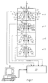
- a web 1 is printed by means of printing units 2, four printing units 2 in the example shown, in face and reverse printing in a web-fed rotary printing press.
- Each of these printing units 2 is designed in a bridge construction symmetrical to the web 1.
- Two rubber cylinders 4, two plate cylinders 6 and the associated inking and dampening units 7, 8 are each mounted in side frames 3 of these printing units 2.
- the inking units 7 are designed as anilox short inking units, each consisting of an ink transfer roller 9, an anilox roller 11 and a doctor blade device 12.
- the dampening units 8 are designed, for example, as spray dampening units and essentially consist of three dampening agent transfer rollers 13, 14, 16 and a spray device 17 which interacts with them.
- the rubber and plate cylinders 4, 6 of a printing unit 2 are connected to one another, for example, via gear transmissions, not shown.
- Each printing unit 2 is driven by its own drive motor.
- This drive motor is e.g. B. flanged directly to the respective rubber cylinder 4 or drives it, for example, by means of an intermediate pinion.
- This rubber cylinder 4 is equipped with a position encoder designed as an angular position encoder, e.g. B. a rotary encoder 18, 19, 21, 22 (z. B. incremental encoder or resolver).
- the printing units 2 can be connected synchronously by means of a standing shaft. It is also possible to provide each rubber and plate cylinder 4, 6 with its own motor.
- each rubber and plate cylinder 4, 6 with its own angular position encoder for. B. a rotary encoder 18, 19, 21, 22 may be equipped.
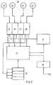
- an evaluation device 23 essentially consists of four measuring cards 24, 26, 27, 28 assigned to the rotary pulse generators 18, 19, 21, 22, a time base 31, a control unit 32, a data memory 33 and a digital I / A assigned to a computer 34.
- O card 36 The four measuring cards 24, 26, 27, 28, each connected to a rotary pulse generator 18, 19, 21, 22, are synchronized by the time base 31.
- this control unit 32 is linked to the time base 31, the data memory 33 and the digital I / O card 36. On the control unit 32 there is a reference psychronization for a start pulse to all Start measuring cards 24, 26, 27, 28 at the same time. In addition, the control unit 32 controls a measurement period, a number of revolutions, the time base 31 and outputs data to the I / O card 36.
- the data memory 33 is also connected to each measuring card 24, 26, 27, 28.
- the digital I / O card 36 connects this evaluation device 23 to the computer 34. Settings of the control unit 32 and data transfer are carried out via this I / O card 36.
- the rotary pulse generators 18, 19, 21, 22 each generate three signals, for example by means of a graduated disk provided with optical markings, which is scanned by opto-electrical converters.
- the first signal provides a reference pulse, the other two signals offset by 90 ° to each other z. B. 4096, meandering pulses per revolution.
- the reference pulse and the two signals are fed to the evaluation device 23, which records all signals synchronously in time.
- a reference signal is also fed to the evaluation device 23.
- This reference signal consists of a temporally constant pulse sequence, the constant frequency of which is substantially higher than a frequency of the signals of the rotary pulse generators 18, 19, 21, 22.
- This high-frequency reference signal is generated by means of an oscillator, e.g. B. a quartz crystal.
- Signals can optionally be compared with one another in the downstream computer 34. So can for example, the signals from rotary pulse generators 18, 19, 21, 22 of two rubber cylinders 4 can be compared with one another during one or more cylinder revolutions.
- This comparison signal generated in this way of two rubber cylinders 4 is a measure of the relative rotation angle deviation (relative movement) of these rubber cylinders 4 to one another and thus corresponds to a deviation of the register of the web 1. If the signals of the rotary pulse generators 18, 19, 21, 22 with the reference signal of the oscillator in Set relationship, these comparison signals thus determined represent a measure of the absolute rotation angle deviation or for the absolute deviation of the circumferential speed of the rubber cylinder 4.
- This comparison signal of the uniformity of the cylinders 4, 6 is fed to the computer 34 and compared there with stored, machine-specific, fixed reference signals for certain production conditions (e.g. speed, number of printing units, web material, etc.).
- machine-typical reference signals were, for example, previously stored for various production conditions on a perfectly functioning rotary printing press in a wear-free and damage-free state or were determined on the basis of theoretical considerations and thus determined.
- both the comparison signal of the uniformity of the cylinders 4, 6 and the pattern signals can be processed. This can be done, for example, using a fast Fourier analysis (FFT). The signals are broken down into frequency spectra with the associated amplitudes.
- FFT fast Fourier analysis
- the cause can be deduced on the basis of their frequency.
- Damage to components e.g. B. gears or cylinder bearings can be recognized, for example, using this frequency analysis.
- wear on the teeth of a gearwheel can be seen in a frequency spectrum that corresponds to a multiple of the cylinder rotation corresponding to the number of teeth. It is also possible to detect progressive wear on cylinder bearings and thus to determine maintenance intervals.
- the deviation of the actual rotation angle position of a cylinder or the deviation of the relative rotation angle position of two cylinders from one another from the associated machine-typical reference signal is used as a measure of the wear or damage to components.
- This state of wear of certain components is continuously monitored and communicated to an operator, for example on a screen of a control center.
- the operator must then, for example, upon reaching a first limit value previously set, for example by the machine manufacturer, acknowledge the message about the state of wear and the machine manually release.
- a second limit value is reached, for example, the machine or at least the relevant unit is stopped.
- the rotary pulse generators 18, 19, 21, 22 required for controlling the motors of the printing units 2 are used to generate the measurement signals.
- Cylinders of other units, such as reel changer, feed mechanism or folder, assigned rotary pulse generators 18, 19, 21, 22 can be used for the evaluation and conclusions can be drawn about the state of wear of certain, periodically moving components of these units. For example, a profile of a cutting force of a cylinder involved in a cutting process, e.g. B. a cutting cylinder can be determined in the folder and conclude from this on the state of wear of, for example, cutting strips or cutting knives.
- rotary pulse generators 18, 19, 21, 22 already required for the drive motors
- other rotary pulse generators can also be used on periodically moving, e.g. B. rotating components, e.g. B. on all cylinders 4, 6, may be provided.
- the measurement signals or the evaluation of the measurement signals can be saved. This stored data can be called up for remote diagnosis if necessary, for example via a modem or ISDN method.
Landscapes
- Engineering & Computer Science (AREA)
- Mechanical Engineering (AREA)
- Inking, Control Or Cleaning Of Printing Machines (AREA)
- Testing Of Devices, Machine Parts, Or Other Structures Thereof (AREA)
- Control Of Presses (AREA)
Priority Applications (1)
| Application Number | Priority Date | Filing Date | Title |
|---|---|---|---|
| EP00128645A EP1110730B1 (fr) | 1996-09-12 | 1997-09-04 | Procédé de diagnose pour une machine rotative |
Applications Claiming Priority (2)
| Application Number | Priority Date | Filing Date | Title |
|---|---|---|---|
| DE19636987A DE19636987C2 (de) | 1996-09-12 | 1996-09-12 | Vorrichtung zur Diagnose bei einer Rotationsdruckmaschine |
| DE19636987 | 1996-09-12 |
Related Child Applications (1)
| Application Number | Title | Priority Date | Filing Date |
|---|---|---|---|
| EP00128645A Division EP1110730B1 (fr) | 1996-09-12 | 1997-09-04 | Procédé de diagnose pour une machine rotative |
Publications (3)
| Publication Number | Publication Date |
|---|---|
| EP0829352A2 true EP0829352A2 (fr) | 1998-03-18 |
| EP0829352A3 EP0829352A3 (fr) | 1998-11-25 |
| EP0829352B1 EP0829352B1 (fr) | 2001-11-07 |
Family
ID=7805308
Family Applications (2)
| Application Number | Title | Priority Date | Filing Date |
|---|---|---|---|
| EP00128645A Expired - Lifetime EP1110730B1 (fr) | 1996-09-12 | 1997-09-04 | Procédé de diagnose pour une machine rotative |
| EP97115305A Expired - Lifetime EP0829352B1 (fr) | 1996-09-12 | 1997-09-04 | Procédé de diagnose pour une machine rotative |
Family Applications Before (1)
| Application Number | Title | Priority Date | Filing Date |
|---|---|---|---|
| EP00128645A Expired - Lifetime EP1110730B1 (fr) | 1996-09-12 | 1997-09-04 | Procédé de diagnose pour une machine rotative |
Country Status (4)
| Country | Link |
|---|---|
| US (1) | US5865120A (fr) |
| EP (2) | EP1110730B1 (fr) |
| JP (1) | JP2978136B2 (fr) |
| DE (3) | DE19636987C2 (fr) |
Cited By (2)
| Publication number | Priority date | Publication date | Assignee | Title |
|---|---|---|---|---|
| EP0976556A1 (fr) * | 1998-07-18 | 2000-02-02 | MAN Roland Druckmaschinen AG | Système d'entretien et diagnostic pour une machine d'impression |
| EP2116378B1 (fr) * | 2008-05-08 | 2015-10-21 | manroland web systems GmbH | Procédé destiné au fonctionnement d'une presse |
Families Citing this family (20)
| Publication number | Priority date | Publication date | Assignee | Title |
|---|---|---|---|---|
| US6301373B1 (en) * | 1998-10-01 | 2001-10-09 | Mcgill University | Paper quality determination and control using scale of formation data |
| US6244175B1 (en) * | 2000-03-27 | 2001-06-12 | Hueiloo Co., Ltd. | Single space rotary printing press for newspapers |
| US6543350B2 (en) * | 2000-05-19 | 2003-04-08 | Intelligent Sensing, Inc. | Measurement system to monitor printing contact pressure |
| DE10259494B4 (de) * | 2002-01-21 | 2017-01-26 | Heidelberger Druckmaschinen Ag | Verfahren zum Steuern einer Druckmaschine |
| CA2440792A1 (fr) * | 2002-09-27 | 2004-03-27 | Mechworks Systems Inc. | Methode et systeme de controle en ligne de l'etat de machines rotatives multietagees |
| WO2004070490A2 (fr) * | 2003-02-04 | 2004-08-19 | Netstal-Maschinen Ag | Unite de maintenance/service et procede de gestion assistee par ordinateur de maintenance et/ou service |
| DE10335862B4 (de) * | 2003-08-06 | 2007-01-04 | Koenig & Bauer Ag | Verfahren zum Kalibrieren eines inkrementalen Winkelgebers an einem rotierenden Bauteil |
| DE102005013361B4 (de) * | 2005-03-23 | 2017-04-13 | Manroland Web Systems Gmbh | Verfahren zur Regelung eines Falzapparats einer Druckmaschine |
| DE102005023482B3 (de) * | 2005-05-21 | 2006-11-16 | Koenig & Bauer Ag | Verfahren zur Diagnose eines Gummituches |
| DE102005042932A1 (de) | 2005-09-09 | 2007-03-22 | Man Roland Druckmaschinen Ag | Druckmaschine, insbesondere Rollendruckmaschine |
| DE102006048353B4 (de) * | 2005-11-07 | 2013-07-25 | Heidelberger Druckmaschinen Ag | Redundant ausgewerteter Winkelgeber |
| US7287473B2 (en) * | 2005-12-20 | 2007-10-30 | Heidelberger Druckmaschinen Ag | Method for selecting printing material in a printing press and printing press |
| US9863917B2 (en) * | 2006-03-20 | 2018-01-09 | Clarkson University | Method and system for real-time vibroacoustic condition monitoring and fault diagnostics in solid dosage compaction presses |
| DE102007020120B4 (de) | 2007-04-28 | 2011-11-17 | Koenig & Bauer Aktiengesellschaft | Verfahren zur Bestimmung von kinematischen Abwickelfehlern an Rotationsdruckmaschinen |
| DE102007054565B3 (de) * | 2007-11-15 | 2008-07-03 | Man Roland Druckmaschinen Ag | Verfahren zum Betreiben einer Bogendruckmaschine |
| US20110225799A1 (en) * | 2010-03-18 | 2011-09-22 | Casio Computer Co., Ltd. | Production apparatus and production method of light emitting device |
| FR2989924A1 (fr) * | 2012-04-27 | 2013-11-01 | Goss Int Corp | Tour d'impression offset pour presse rotative |
| SE543357C2 (en) * | 2018-06-29 | 2020-12-15 | Baldwin Jimek Ab | Service tracking system for spray bars and the like |
| DE102021103214A1 (de) | 2021-02-11 | 2022-08-11 | Koenig & Bauer Ag | Verfahren zur Maschinenüberwachung während des Betriebes einer Verarbeitungsmaschine |
| DE102022110168B3 (de) | 2022-04-27 | 2023-05-17 | Heidelberger Druckmaschinen Aktiengesellschaft | Funktionsüberwachung von Transportbändern in der Druckmaschine |
Citations (5)
| Publication number | Priority date | Publication date | Assignee | Title |
|---|---|---|---|---|
| FR2105663A5 (fr) * | 1970-09-16 | 1972-04-28 | Chambon Automation | |
| DE3707866A1 (de) * | 1986-03-17 | 1987-10-01 | Bobst Sa | Verfahren und vorrichtung fuer die steuerung der einstellung der organe von druckerei- und kartoniermaschinen |
| DE4136785A1 (de) * | 1991-11-08 | 1993-05-13 | Kba Planeta Ag | Diagnoseeinrichtung fuer eine takterzeugungseinrichtung an druckmaschinen |
| DE4137979A1 (de) * | 1991-11-19 | 1993-05-27 | Heidelberger Druckmasch Ag | Antrieb fuer eine druckmaschine mit mehreren druckwerken |
| DE19505692A1 (de) * | 1995-02-20 | 1996-08-22 | Roland Man Druckmasch | Druckmaschine |
Family Cites Families (5)
| Publication number | Priority date | Publication date | Assignee | Title |
|---|---|---|---|---|
| US3713571A (en) * | 1971-05-18 | 1973-01-30 | Dale Prod Inc | Method and apparatus for feeding strip material |
| US4528630A (en) * | 1982-09-14 | 1985-07-09 | Oao Corporation | Automatic registration control method and apparatus |
| FR2716935B1 (fr) * | 1994-03-07 | 1996-05-31 | Solex | Collecteur d'admission à impédance modulable et faible perte de charge. |
| US5615609A (en) * | 1995-08-21 | 1997-04-01 | The Lawrence Paper Company | System and method for controlling AC motor driven multi-unit printing press |
| US5678159A (en) * | 1996-06-26 | 1997-10-14 | Xerox Corporation | Sheet registration and deskewing device |
-
1996
- 1996-09-12 DE DE19636987A patent/DE19636987C2/de not_active Expired - Fee Related
-
1997
- 1997-09-04 DE DE59709591T patent/DE59709591D1/de not_active Expired - Fee Related
- 1997-09-04 DE DE59705254T patent/DE59705254D1/de not_active Expired - Fee Related
- 1997-09-04 EP EP00128645A patent/EP1110730B1/fr not_active Expired - Lifetime
- 1997-09-04 EP EP97115305A patent/EP0829352B1/fr not_active Expired - Lifetime
- 1997-09-10 JP JP9245441A patent/JP2978136B2/ja not_active Expired - Fee Related
- 1997-09-12 US US08/928,332 patent/US5865120A/en not_active Expired - Fee Related
Patent Citations (5)
| Publication number | Priority date | Publication date | Assignee | Title |
|---|---|---|---|---|
| FR2105663A5 (fr) * | 1970-09-16 | 1972-04-28 | Chambon Automation | |
| DE3707866A1 (de) * | 1986-03-17 | 1987-10-01 | Bobst Sa | Verfahren und vorrichtung fuer die steuerung der einstellung der organe von druckerei- und kartoniermaschinen |
| DE4136785A1 (de) * | 1991-11-08 | 1993-05-13 | Kba Planeta Ag | Diagnoseeinrichtung fuer eine takterzeugungseinrichtung an druckmaschinen |
| DE4137979A1 (de) * | 1991-11-19 | 1993-05-27 | Heidelberger Druckmasch Ag | Antrieb fuer eine druckmaschine mit mehreren druckwerken |
| DE19505692A1 (de) * | 1995-02-20 | 1996-08-22 | Roland Man Druckmasch | Druckmaschine |
Non-Patent Citations (2)
| Title |
|---|
| HERBERT STöCKL UND HANS MAMBERER: 'Kann Dublieren als Folge von Drehschwingungen auftreten?' DER POLYGRAPH Oktober 1974, Seiten 729 - 734 * |
| PROF. DR. SC. TECHN. RUDOLF RUDER ET AL.: "Erhöhung der Zuverlässigkeit polygraphischer Maschinen durch technische Diagnose" PAPIER UND DRUCK, Bd. 7, 1983, ALLGEMEINER TEIL, Seiten 100-104, XP002075846 * |
Cited By (2)
| Publication number | Priority date | Publication date | Assignee | Title |
|---|---|---|---|---|
| EP0976556A1 (fr) * | 1998-07-18 | 2000-02-02 | MAN Roland Druckmaschinen AG | Système d'entretien et diagnostic pour une machine d'impression |
| EP2116378B1 (fr) * | 2008-05-08 | 2015-10-21 | manroland web systems GmbH | Procédé destiné au fonctionnement d'une presse |
Also Published As
| Publication number | Publication date |
|---|---|
| EP1110730A3 (fr) | 2001-08-22 |
| JP2978136B2 (ja) | 1999-11-15 |
| DE19636987C2 (de) | 2000-03-23 |
| DE59709591D1 (de) | 2003-04-24 |
| US5865120A (en) | 1999-02-02 |
| JPH1086342A (ja) | 1998-04-07 |
| DE19636987A1 (de) | 1998-03-19 |
| EP0829352B1 (fr) | 2001-11-07 |
| DE59705254D1 (de) | 2001-12-13 |
| EP1110730A2 (fr) | 2001-06-27 |
| EP0829352A3 (fr) | 1998-11-25 |
| EP1110730B1 (fr) | 2003-03-19 |
Similar Documents
| Publication | Publication Date | Title |
|---|---|---|
| EP0829352B1 (fr) | Procédé de diagnose pour une machine rotative | |
| DE19527199C2 (de) | Flexodruckmaschine und deren Verwendung | |
| EP0916486B2 (fr) | Système d'entrainement électrique pour le positionnemnt d'un ou plusieurs éléments dans des machines ; dispositif d'entrainement avec un indicateur d'angle et machine d'impression | |
| DE3148449C1 (de) | Verfahren zur Verringerung von Registerfehlern und Druckmaschine zur Durchfuehrung des Verfahrens | |
| DE2930438C2 (de) | Verfahren zum Voreinstellen des Registers bei Rollen-Rotations-Tiefdruckmaschinen | |
| EP1135256B1 (fr) | Procede de regulation d'un registre | |
| EP0683729B1 (fr) | Procede de commande d'une machine a cylindre pour la serigraphie | |
| EP1211068B1 (fr) | Procédé pour réduire les vibrations dans une machine d'impression | |
| EP1612043A1 (fr) | Procédé d'entrainement de rouleaux d'une unité d'impression d'une machine à imprimer | |
| EP1531992B1 (fr) | Dispositif d'entrainement et procede pour assurer la commande d'une unite d'imprimante | |
| DE68917406T2 (de) | Individuelle Antriebsvorrichtung für Druckeinheiten. | |
| DE10335862B4 (de) | Verfahren zum Kalibrieren eines inkrementalen Winkelgebers an einem rotierenden Bauteil | |
| DE102006015597B4 (de) | Verfahren zur Erkennung und Vermeidung einer kritischen Drehzahl | |
| DE102007020727A1 (de) | Druckmaschine und Verfahren zum Betreiben einer Druckmaschine | |
| DE3535579A1 (de) | Einrichtung zur registereinstellung an druckmaschinen | |
| DE602004004633T2 (de) | Methode und Vorrichtung zur anfänglichen Regelung der Registerhaltigkeit von Tiefdruckzylindern in einer Mehrfarben-Rotationsdruckmaschine | |
| DE10204514B4 (de) | Vorrichtung und Verfahren zur Korrektur des Längsregisterfehlers, welcher durch die Beistellung auftritt | |
| DE102009045679B4 (de) | Verfahren zur Regelung eines Antriebes wenigstens eines registerhaltig anzutreibenden Rotationskörpers einer Druckmaschine | |
| DE102008000184B4 (de) | Verfahren zur Verringerung bzw. Vermeidung von Abwickelfehlern an Rotationsdruckmaschinen | |
| DE10036989C2 (de) | Bahnverarbeitende Maschine und Verfahren zu deren Betrieb | |
| EP0747215B1 (fr) | Dispositif de commande pour une machine à imprimer | |
| EP0294674B1 (fr) | Procédé et dispositif pour la surveillance des courroies tangentielles d'une machine pour la production de fils tournés ou retordus | |
| DE3634811A1 (de) | Verfahren und schaltungsanordnung zum normierten anzeigen der druckfarbenzufuhr | |
| DE102008000189A1 (de) | Verfahren zur Korrektur von kinematischen Abwickelfehlern an einer Rotationsdruckmaschine | |
| DE2314045A1 (de) | Einrichtung an bahnfuehrenden maschinen zur laengenmessung und zum feststellen von laengenaenderungen an der laufenden bahn |
Legal Events
| Date | Code | Title | Description |
|---|---|---|---|
| PUAI | Public reference made under article 153(3) epc to a published international application that has entered the european phase |
Free format text: ORIGINAL CODE: 0009012 |
|
| AK | Designated contracting states |
Kind code of ref document: A2 Designated state(s): CH DE FR GB IT LI |
|
| AX | Request for extension of the european patent |
Free format text: AL;LT;LV;RO;SI |
|
| PUAL | Search report despatched |
Free format text: ORIGINAL CODE: 0009013 |
|
| AK | Designated contracting states |
Kind code of ref document: A3 Designated state(s): AT BE CH DE DK ES FI FR GB GR IE IT LI LU MC NL PT SE |
|
| AX | Request for extension of the european patent |
Free format text: AL;LT;LV;RO;SI |
|
| RAP1 | Party data changed (applicant data changed or rights of an application transferred) |
Owner name: KOENIG & BAUER AKTIENGESELLSCHAFT |
|
| 17P | Request for examination filed |
Effective date: 19990520 |
|
| AKX | Designation fees paid |
Free format text: CH DE FR GB IT LI |
|
| 17Q | First examination report despatched |
Effective date: 19991104 |
|
| RTI1 | Title (correction) |
Free format text: METHOD FOR THE DIAGNOSIS OF A ROTARY PRINTING PRESS |
|
| GRAG | Despatch of communication of intention to grant |
Free format text: ORIGINAL CODE: EPIDOS AGRA |
|
| GRAG | Despatch of communication of intention to grant |
Free format text: ORIGINAL CODE: EPIDOS AGRA |
|
| GRAH | Despatch of communication of intention to grant a patent |
Free format text: ORIGINAL CODE: EPIDOS IGRA |
|
| GRAH | Despatch of communication of intention to grant a patent |
Free format text: ORIGINAL CODE: EPIDOS IGRA |
|
| GRAA | (expected) grant |
Free format text: ORIGINAL CODE: 0009210 |
|
| AK | Designated contracting states |
Kind code of ref document: B1 Designated state(s): CH DE FR GB IT LI |
|
| REG | Reference to a national code |
Ref country code: CH Ref legal event code: EP |
|
| GBT | Gb: translation of ep patent filed (gb section 77(6)(a)/1977) |
Effective date: 20011107 |
|
| REF | Corresponds to: |
Ref document number: 59705254 Country of ref document: DE Date of ref document: 20011213 |
|
| REG | Reference to a national code |
Ref country code: GB Ref legal event code: IF02 |
|
| PLBE | No opposition filed within time limit |
Free format text: ORIGINAL CODE: 0009261 |
|
| STAA | Information on the status of an ep patent application or granted ep patent |
Free format text: STATUS: NO OPPOSITION FILED WITHIN TIME LIMIT |
|
| 26N | No opposition filed | ||
| PGFP | Annual fee paid to national office [announced via postgrant information from national office to epo] |
Ref country code: CH Payment date: 20080926 Year of fee payment: 12 |
|
| PGFP | Annual fee paid to national office [announced via postgrant information from national office to epo] |
Ref country code: IT Payment date: 20080926 Year of fee payment: 12 |
|
| PGFP | Annual fee paid to national office [announced via postgrant information from national office to epo] |
Ref country code: GB Payment date: 20080924 Year of fee payment: 12 |
|
| PGFP | Annual fee paid to national office [announced via postgrant information from national office to epo] |
Ref country code: DE Payment date: 20080929 Year of fee payment: 12 |
|
| PGFP | Annual fee paid to national office [announced via postgrant information from national office to epo] |
Ref country code: FR Payment date: 20080922 Year of fee payment: 12 |
|
| REG | Reference to a national code |
Ref country code: CH Ref legal event code: PL |
|
| GBPC | Gb: european patent ceased through non-payment of renewal fee |
Effective date: 20090904 |
|
| REG | Reference to a national code |
Ref country code: FR Ref legal event code: ST Effective date: 20100531 |
|
| PG25 | Lapsed in a contracting state [announced via postgrant information from national office to epo] |
Ref country code: FR Free format text: LAPSE BECAUSE OF NON-PAYMENT OF DUE FEES Effective date: 20090930 Ref country code: DE Free format text: LAPSE BECAUSE OF NON-PAYMENT OF DUE FEES Effective date: 20100401 |
|
| PG25 | Lapsed in a contracting state [announced via postgrant information from national office to epo] |
Ref country code: LI Free format text: LAPSE BECAUSE OF NON-PAYMENT OF DUE FEES Effective date: 20090930 Ref country code: CH Free format text: LAPSE BECAUSE OF NON-PAYMENT OF DUE FEES Effective date: 20090930 |
|
| PG25 | Lapsed in a contracting state [announced via postgrant information from national office to epo] |
Ref country code: GB Free format text: LAPSE BECAUSE OF NON-PAYMENT OF DUE FEES Effective date: 20090904 |
|
| PG25 | Lapsed in a contracting state [announced via postgrant information from national office to epo] |
Ref country code: IT Free format text: LAPSE BECAUSE OF NON-PAYMENT OF DUE FEES Effective date: 20090904 |