EP0827902A2 - Antinick-Fahrradbremsanlage - Google Patents
Antinick-Fahrradbremsanlage Download PDFInfo
- Publication number
- EP0827902A2 EP0827902A2 EP97303748A EP97303748A EP0827902A2 EP 0827902 A2 EP0827902 A2 EP 0827902A2 EP 97303748 A EP97303748 A EP 97303748A EP 97303748 A EP97303748 A EP 97303748A EP 0827902 A2 EP0827902 A2 EP 0827902A2
- Authority
- EP
- European Patent Office
- Prior art keywords
- rear wheel
- braking
- suspension mechanism
- wheel suspension
- braking system
- Prior art date
- Legal status (The legal status is an assumption and is not a legal conclusion. Google has not performed a legal analysis and makes no representation as to the accuracy of the status listed.)
- Withdrawn
Links
Images
Classifications
-
- B—PERFORMING OPERATIONS; TRANSPORTING
- B62—LAND VEHICLES FOR TRAVELLING OTHERWISE THAN ON RAILS
- B62K—CYCLES; CYCLE FRAMES; CYCLE STEERING DEVICES; RIDER-OPERATED TERMINAL CONTROLS SPECIALLY ADAPTED FOR CYCLES; CYCLE AXLE SUSPENSIONS; CYCLE SIDECARS, FORECARS, OR THE LIKE
- B62K25/00—Axle suspensions
- B62K25/04—Axle suspensions for mounting axles resiliently on cycle frame or fork
- B62K25/28—Axle suspensions for mounting axles resiliently on cycle frame or fork with pivoted chain-stay
- B62K25/286—Axle suspensions for mounting axles resiliently on cycle frame or fork with pivoted chain-stay the shock absorber being connected to the chain-stay via a linkage mechanism
-
- B—PERFORMING OPERATIONS; TRANSPORTING
- B62—LAND VEHICLES FOR TRAVELLING OTHERWISE THAN ON RAILS
- B62L—BRAKES SPECIALLY ADAPTED FOR CYCLES
- B62L3/00—Brake-actuating mechanisms; Arrangements thereof
Definitions
- the present invention relates generally to bicycles, and more particularly to a bicycle braking system which is specifically adapted to counter the unweighting (i.e., "dive") of the rear wheel suspension mechanism of the bicycle normally induced by the weight transfer resulting from the braking of the bicycle.
- Applicant has found that the unweighting or dive of the rear wheel suspension mechanism of a bicycle may be countered by transferring the braking force/energy applied to the rear wheel directly to the rear wheel suspension mechanism so a to facilitate the actuation thereof.
- the actuation of the rear wheel suspension mechanism, and more particularly its shock absorber causes the braking force/energy to be absorbed thereby, thus countering the dive effect.
- Applicant has developed a bicycle braking system which is separate from but connected to the rear wheel suspension mechanism.
- the braking system is selectively engageable to a braking surface of the rear wheel, and is configured such that the engagement thereof to the braking surface facilitates the transfer of braking force to and the actuation of the rear wheel suspension mechanism in a manner countering the unweighting thereof normally resulting from the braking of the bicycle.
- the present bicycle braking system may be selectively tuned such that the anti-dive effect facilitated thereby is weaker, equal to, or stronger than the dive induced by weight transfer during bicycle braking.
- a bicycle braking system which is adapted to transfer braking force/energy to the rear wheel suspension mechanism of the bicycle for creating an anti-dive effect.
- the bicycle braking system of the present invention comprises a bicycle frame having a rear wheel suspension mechanism connected thereto. Rotatably connected to the rear wheel suspension mechanism is the rear wheel axle of the bicycle rear wheel which includes a braking surface. Pivotally connected to the rear wheel suspension mechanism is a caliper arm, while attached to the caliper arm is a brake caliper which is selectively engageable to the braking surface.
- the braking system of the present invention further comprises a pull link having a first end which is pivotally connected to the caliper arm and a second end which is pivotally connected to the rear wheel suspension mechanism.
- the engagement of the brake caliper to the braking surface induces the pivotal movement of the caliper arm which facilitates the transfer of braking force to and the actuation of the rear wheel suspension mechanism in a manner countering the unweighting thereof normally resulting from the braking of the bicycle.
- the frictional force exerted on the brake caliper when the same engages the braking surface in combination with the rotational movement of the brake caliper/caliper arm is a source of braking force/energy which is introduced into the rear wheel suspension mechanism to facilitate the actuation thereof.
- the braking surface of the rear wheel is preferably defined by a circularly configured brake rotor plate which is attached to the rear wheel axle and rotates therewith.
- the caliper arm preferably pivots about an axis which extends in generally parallel relation to the axis of the rear wheel axle, or may alternatively pivot about an axis which is coaxially aligned with the axis of the rear wheel axle.
- the caliper arm may be pivotally anchored directly to the rear wheel axle and pivot about its axis.
- the amount of braking force/energy absorbed by the rear wheel suspension mechanism may be modified by adjusting the location(s) of the pivot point(s) of the braking system 12 (e.g., the pivot point location of the caliper arm relative to the axis of the rear wheel axle) and the relative angles of the components thereof.
- the rear wheel suspension mechanism itself preferably comprises an upper link which is pivotally connected to the bicycle frame.
- the rear wheel suspension mechanism includes a pair of seat stay members, the upper ends of which are pivotally connected to the upper link. Attached to the lower ends of respective ones of the seat stay members is a pair of rear wheel carrying members for receiving the rear wheel axle.
- the caliper arm of the braking system is itself pivotally connected to one of the rear wheel carrying members.
- Pivotally connected to the bicycle frame are the front ends of a pair of chain stay members, the back of ends of which are pivotally connected to respective ones of the rear wheel carrying members.
- the second end of the connector link is itself pivotally connected to one of the chain stay members.
- the rear wheel suspension mechanism further comprises a shock absorber having a first end which is connected to the seat stay members, and a second end which is connected to the upper link.
- the pivotal movement of the caliper arm facilitates the transfer of the braking force to the rear wheel suspension mechanism, and in particular to the shock absorber thereof.
- the braking force is converted to a compressive force which acts on the shock absorber and facilitates the compression of the same, which has the effect of partially, fully, or over compensating for shock absorber unloading attributable to rear brake induced dive of the bicycle.
- Such compensation is achieved by the absorption of the braking force facilitated by the compression of the shock absorber.
- the rear wheel suspension mechanism further comprises a shock support which is attached to and extends between the seat stay members, with the first end of the shock absorber being connected to the shock support.
- the shock absorber itself comprises an upper retaining plate which is attached to the upper link, and a lower retaining plate which is attached to the shock support extending between the seat stay members.
- Firmly seated between the upper and lower retaining plates is a springing member which is preferably fabricated from an elastomeric material. The springing member is compressed between the upper and lower retaining plates to provide a pre-load thereto, with the pivotal movement of the caliper arm facilitating the compression thereof.
- the shock absorber may also comprise a coil-spring/damper which is pivotally mounted to and extends between the upper link and the shock support. Also included in the rear wheel suspension mechanism is a pull link receiving tab which is attached to one of the chain stay members, with the second end of the pull link being pivotally connected to the pull link receiving tab.
- the bicycle frame included in the braking system of the present invention preferably comprises a head tube disposed at the front end thereof, and an elongate seat tube disposed at the back end thereof. Rigidly attached to respective ones of the head and seat tubes are the opposed ends of an elongate top tube or cross bar.
- the rear wheel suspension mechanism, and in particular the upper link and front ends of the chain stay members, are preferably connected to the seat tube of the bicycle frame.
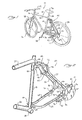
- FIG. 1 perspectively illustrates a bicycle 10 incorporating the anti-dive braking system 12 constructed in accordance with the present invention.
- the bicycle 10 comprises a bicycle frame 14 including a head tube 16 disposed at the front end of the bicycle 10 and an elongate seat tube 18 disposed toward the back end of the bicycle 10.
- a stem 20 having the handle bars 22 attached to the top end thereof.
- Attached to the bottom end of the stem 20 is a front fork assembly 24.
- Rotatably connected to the front fork assembly 24 is the axle of the front wheel 26.
- the front fork assembly 24 may be provided with shock absorbing capability.
- Telescopically received into the top end of the seat tube 18 is a seat post 28 having a saddle or seat 30 connected to the top end thereof.
- the bicycle frame 14 further comprises an elongate cross bar or top tube 32 having opposed ends which are rigidly attached to respective ones of the head and seat tubes 16, 18.
- Rigidly attached to the bottom end of the seat tube 18 is a cylindrically configured axle receiving bracket 34 having a bore extending axially therethrough.
- the bore of the axle receiving bracket 34 is adapted to receive a bottom bracket axle of the bicycle 10 which includes a pair of cranks 36 attached to respective ones of the opposed end thereof.
- cranks 36 Rotatably connected to the distal ends of the cranks 36 are the pedals 38.
- a chain wheel which is adapted to rotate concurrently with the bottom bracket axle.
- the head, seat, top and down tubes 16, 18, 32, 40 each typically have generally cylindrical configurations, and are secured to one another via welded or brazed connections.
- the rear wheel suspension mechanism 42 comprises an upper link 44 which is pivotally connected to the seat tube 18 via a link bracket 46.
- the link bracket 46 is rigidly attached to the back of the seat tube 18, and defines a pair of triangularly configured flange portions which extend in opposed, spaced relation to each other. Disposed within the flange portions and extending laterally therethrough is a pair of coaxially aligned apertures. The attachment of the link bracket 46 to the seat tube 18 is preferably facilitated through a welding or brazing process.
- the upper link 44 of the rear wheel suspension mechanism 42 has a generally H-shaped configuration, and includes front and back pairs of mounting ears which are separated by a generally planar central base portion 48. Disposed within the front pair of mounting ears and extending laterally therethrough is a pair of coaxially aligned apertures.
- the pivotal connection of the upper link 44 to the link bracket 46 is facilitated by initially inserting the front pair of mounting ears between the flange portions of the link bracket 46. In this respect, the distance separating the flange portions of the link bracket 46 from each other is adapted to slidably accommodate the front pair of mounting ears of the upper link 44 therebetween.
- the apertures disposed within the front pair of mounting ears are coaxially aligned with those disposed within the flange portions, with a fastener 50 being extended through the coaxially aligned apertures to facilitate the pivotal connection of the upper link 44 to the link bracket 46.
- the rear wheel suspension mechanism 42 of the bicycle 10 further comprises a pair of identically configured seat stay members 52 having upper ends which are pivotally connected to the upper link 44, and more particularly to the back pair of mounting ears of the upper link 44. Rigidly attached to the lower ends of respective ones of the seat stay members 52 is a pair of rear wheel carrying members 54 which are adapted to receive the rear wheel axle 56 of the bicycle rear wheel 58.
- the rear wheel axle 56 includes a circularly configured brake rotor plate 60 attached thereto and rotatable concurrently therewith.
- the brake rotor plate 60 defines generally planar inner and outer braking surfaces, and interacts with the braking system 12 in a manner which will be discussed in more detail below.
- a rear sprocket which is cooperatively engaged to the chain wheel of the bicycle 10 via a chain.
- the upper portions of the seat stay members 52 are arcuately contoured, and are bowed inwardly toward the seat tube 18 when pivotally connected to the upper link 44.
- a shock support 62 Rigidly attached to and extending between the arcuately contoured portions of the seat stay members 52 is a shock support 62 which is also directed inwardly toward the seat tube 18.
- the shock support 62 includes a pair of triangularly configured leg portions which are rigidly attached to respective ones of the seat stay members 52 via a welding or brazing process. Extending between the leg portions of the shock support 62 is a generally planar middle portion.
- the rear wheel suspension mechanism 42 of the bicycle 10 includes a pair of chain stay members 64, the front ends of which are pivotally connected to the seat tube 18.
- the connection of the chain stay members 64 to the seat tube 18 is preferably facilitated by a chain stay end housing 66 which is rigidly attached to the front ends of the chain stay members 64 via a welding or brazing process and is pivotally connected to the seat tube 18 via a fastener 68.
- the back ends of the chain stay members 64 are themselves pivotally connected to respective ones of the rear wheel carrying members 54.
- each rear wheel carrying member 54 is inserted into the space defined between the juxtaposed prong portions of a respective clevis member 70, with such prong portions being separated from each other by a distance sufficient to allow the frontal portion of the rear wheel carrying member 54 to be slidably inserted therebetween.
- the frontal portion of the rear wheel carrying member 54 is oriented within a respective clevis member 70 such that an aperture disposed therein is coaxially aligned with a pair of apertures extending laterally through the prong portions of the clevis member 70.
- a fastener 72 such as a pivot pin is extended through the coaxially aligned apertures of the prong portions and the frontal portion, thus pivotally connecting the rear wheel carrying member 54 to the clevis member 70, and hence a respective chain stay member 64.
- the rear wheel suspension mechanism 42 of the bicycle 10 includes a shock absorber 74.
- the shock absorber 74 comprises an upper retaining plate (not shown) which is rigidly attached to the upper link 44, and more particularly to the lower surface of the base portion 48 thereof.
- the upper retaining plate defines a generally circular central portion having a peripheral flange portion extending angularly outward therefrom, thus giving the upper retaining plate a generally pan-like configuration.
- the upper retaining plate is oriented upon the lower surface of the base portion 48 such that its flange portion extends outwardly therefrom.
- the shock absorber 74 includes a lower retaining plate 76 which is configured identically to the upper retaining plate, and is rigidly attached to the shock support 62, and more particularly the upper surface of the middle portion thereof.
- the lower retaining plate 76 is itself oriented upon the upper surface of the middle portion such that its flange portion extends outwardly therefrom.
- the shock absorber 74 further comprises an elongate, cylindrically configured dampening or springing member 78 which is preferably fabricated from an elastomeric material and is firmly seated between the upper retaining plate and lower retaining plate 76.
- the springing member 78 is preferably compressed between the upper and lower retaining plates to provide a pre-load thereto. Such compression is typically achieved by sizing the springing member 78 such that when the upper and lower retaining plates are positioned on the opposed ends thereof, the distance separating the outer surfaces of the central portions of the upper and lower retaining plates slightly exceeds the distance separating the lower surface of the base portion 48 from the upper surface of the middle portion of the shock support 62.
- the springing member 78 be slightly compressed to enable the upper and lower retaining plates to be inserted and properly oriented between the upper link 44 and shock support 62.
- the springing member 78 need not be compressed between the upper and lower retaining plates of the shock absorber 74, and may alternatively be mechanically fastened thereto.
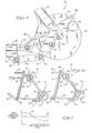
- the shock absorber 74 When the shock absorber 74 is in its normal, uncompressed state (as shown in Figure 4a), the opposed ends of the springing member 78 are in contact with only the central portions of the upper and lower retaining plates, with gaps being defined between the outer surface of the springing member 78 and the flange portions of the upper and lower retaining plates.
- the rear wheel carrying members 54 When a shock force is applied to the rear wheel 58 of the bicycle 10, the rear wheel carrying members 54 are moved upwardly, thus resulting in the upward planar motion of the seat stay members 52.
- the upward planar motion of the seat stay members 52 in turn causes the upper link 44 to be pivoted upwardly about the axis of the fastener 50.
- the upper and lower retaining plates may be rigidly, rather than pivotally attached to the upper link 44 and shock support 62 since the opposed ends of the springing member 78 will conform to the motion of the upper and lower retaining plates.
- the springing member 78 is compressed, the same is maintained between the upper and lower retaining plates by the flange portions thereof against which the end portions of the springing members 78 are abutted when the same is compressed.
- shock absorber 74 may alternatively comprise a conventional coil-spring type shock absorber. If this type of shock absorber is employed in the rear wheel suspension mechanism 42, it will further be recognized that one or both of the opposed ends thereof will be pivotally connected to the upper link 44 and/or shock support 62.
- the braking system 12 of the bicycle 10 comprises a caliper arm 80 which is pivotally connected to one of the rear wheel carrying members 54 via a fastener 82 such as a pivot pin.
- the axis of the fastener 82 i.e., the axis of the pivot point of the caliper arm 80
- the axes of the fastener 82 and rear wheel axle 56 preferably being disposed in relative close proximity to each other.
- the orientation of the axes of the fastener 82 and rear wheel axle 56 in close proximity to each other provides an anti-lock function to the braking system 12.
- the caliper arm 80 may be pivotally anchored directly to the rear wheel axle 56, thus causing the caliper arm 80 to pivot about the axis of the rear wheel axle 56.
- the advantages attendant to modifying the location of the pivot point of the caliper arm 80 relative to the axis of the rear wheel axle 56 will be discussed in more detail below.
- the caliper arm 80 of the braking system 12 has a bent configuration, and defines an upper end 84, a lower end 86, and a reduced width central portion 88.
- the pivot point of the caliper arm 80 as shown in Figure 3 is located in the lower half thereof, between the central portion 88 and lower end 86.
- Attached to the upper end 84 of the caliper arm 80 is a conventional brake caliper 90.
- the brake caliper 90 when actuated, is adapted to engage the inner and outer braking surfaces defined by the brake rotor plate 60 attached to the rear wheel axle 56.
- the actuation of the brake caliper 90 facilitates the application of a frictional force to the inner and outer braking surfaces of the brake rotor plate 60, thus slowing the rotation of the brake rotor plate 60, and hence the rear wheel 58.
- the braking system 12 includes a pull link 92 having a first or back end which is pivotally connected to the lower end 86 of the caliper arm 80 via a fastener 94 such as a pivot pin.
- the pull link 92 further includes a second or front end which is pivotally connected to a pull link receiving tab 96 rigidly attached to one of the chain stay members 64 via a welding or brazing process.
- the pivotal connection of the pull link 92 to the pull link receiving tab 96 is facilitated by a fastener 98 such as a pivot pin. It will be recognized that the pull link receiving tab 96 is rigidly attached to that chain stay member 64 of the pair which is pivotally connected to the rear wheel carrying member 54 having the caliper arm 80 connected thereto.
- the positive moment on (counter-clockwise pivotal movement of) the caliper arm 80 is induced by the frictional force exerted on the actuated brake caliper 90 by the brake rotor plate 60 in combination with the pivotal mounting of the caliper arm 80 to the rear wheel carrying member 54 via the fastener 82.
- the frictional force is exerted upon the brake caliper 90 when the same engages the brake rotor plate 60.
- Such frictional force is a source of braking force which is transmitted to the caliper arm 80.
- the actuation of the rear wheel suspension mechanism 42 counters the unweighting or dive thereof normally resulting from the braking of the rear wheel 58.
- the rear wheel suspension mechanism 42 and more particularly the shock absorber 74 thereof, absorbs the braking force transferred to the seat stay members 52 by the caliper arm 80, thus creating an anti-dive effect.
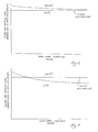
- the braking force applied to the rear wheel suspension mechanism 42 as a result of the braking of the rear wheel 58 in the aforementioned manner is substantially constant throughout the range of travel of the rear wheel suspension mechanism 42.
- a performance curve closer to that shown by line B can be accomplished in the braking system 12 by adjusting the location(s) of the pivot point(s) of the braking system 12 (e.g., the pivot point location of the caliper arm 80 (i.e., the axis of the fastener 82) relative to the axis of the rear wheel axle 56) and the relative angles of the caliper arm 80 and pull link 92.
- the amount of braking force transferred to the rear wheel suspension mechanism 42 can be selectively increased or decreased by modifying the location of the caliper arm 80 pivot point, thus allowing the braking system 12 to be tuned to facilitate no dive at all or even a positive squat of the rear wheel suspension mechanism 42 during the braking of the bicycle 10.
- FIGs 6 and 7 graphically illustrate the manner in which the braking system 12 of the present invention can be selectively “tuned”.
- the performance characteristics of the braking system 12 can be modified from that shown in Figure 6 to that shown in Figure 7 by moving the location of the pivot point of the caliper arm 80 (i.e., the location of the fastener 82) forward relative to the rear wheel carrying member 54 and shortening the length of the pull link 92.
- Such movement of the pivot point defined by the fastener 82 forward and shortening of the pull link 92 facilitates a "falling rate" effect in the braking system 12.
- the braking force/energy can be transferred to the rear wheel suspension mechanism 42 via the previously described mechanical linkage system, or alternatively through the utilization of a hydraulic system alone or in combination with a mechanical linkage system. Additionally, any such system or combination thereof can be adapted to constantly or variably amplify the braking force/energy as a function of the position of the rear wheel suspension mechanism 42. The transferred braking force/energy can also be applied to the rear wheel suspension system 42 in the aforementioned manner, or directly to the shock absorber 74 without first being transmitted through the seat stay members 52 of the rear wheel suspension mechanism 42.
Landscapes
- Engineering & Computer Science (AREA)
- Mechanical Engineering (AREA)
- Axle Suspensions And Sidecars For Cycles (AREA)
- Braking Arrangements (AREA)
Applications Claiming Priority (2)
| Application Number | Priority Date | Filing Date | Title |
|---|---|---|---|
| US707670 | 1985-03-04 | ||
| US08/707,670 US5901974A (en) | 1996-09-04 | 1996-09-04 | Bicycle, anti-dive braking system |
Publications (2)
| Publication Number | Publication Date |
|---|---|
| EP0827902A2 true EP0827902A2 (de) | 1998-03-11 |
| EP0827902A3 EP0827902A3 (de) | 1998-12-09 |
Family
ID=24842654
Family Applications (1)
| Application Number | Title | Priority Date | Filing Date |
|---|---|---|---|
| EP97303748A Withdrawn EP0827902A3 (de) | 1996-09-04 | 1997-06-03 | Antinick-Fahrradbremsanlage |
Country Status (3)
| Country | Link |
|---|---|
| US (2) | US5901974A (de) |
| EP (1) | EP0827902A3 (de) |
| TW (1) | TW324698B (de) |
Cited By (4)
| Publication number | Priority date | Publication date | Assignee | Title |
|---|---|---|---|---|
| GB2359051A (en) * | 2000-02-11 | 2001-08-15 | Maverick American Llc | Suspension system for a vehicle |
| WO2003018392A1 (en) * | 2001-08-22 | 2003-03-06 | Rocky Mountain Bicycles, A Division Of Procycle Group Inc. | Rear suspension system for two-wheeled vehicles, particularly bicycles |
| US7216883B2 (en) | 2005-03-02 | 2007-05-15 | Rocky Mountain Bicycles-A Division Of Procycle Group Inc. | Bicycle with rear suspension |
| US7635141B2 (en) | 2007-06-07 | 2009-12-22 | Rocky Mountain Bicycles - A Division Of Procycle Group Inc. | Bicycle rear suspension system |
Families Citing this family (41)
| Publication number | Priority date | Publication date | Assignee | Title |
|---|---|---|---|---|
| AU3334497A (en) * | 1997-04-16 | 1998-11-11 | Karl-Heinz Hansmann | Electronic emergency call anc locating system for rescuing persons in distress |
| FR2762572B1 (fr) * | 1997-04-25 | 1999-06-04 | Renault Sport | Suspension arriere pour bicyclette |
| US6336648B1 (en) | 1997-12-15 | 2002-01-08 | David D. Bohn | Electronically controlled anti-dive suspension apparatus for two-wheeled vehicles |
| US6164676A (en) * | 1998-02-20 | 2000-12-26 | Trek Bicycle Corporation | Variable reduction cross-linkage for rear suspension bicycle |
| US6203042B1 (en) | 1998-02-20 | 2001-03-20 | Trek Bicycle Corporation | Bicycle rear suspension system providing relative rearward motion of rear axle |
| WO1999044880A1 (en) | 1998-03-02 | 1999-09-10 | Ellsworth Anthony S | Bicycle suspension apparatus and related method |
| US7296815B2 (en) * | 1998-03-02 | 2007-11-20 | Anthony S. Ellsworth | Bicycle suspension apparatus and related method |
| US20030205882A1 (en) * | 2001-05-16 | 2003-11-06 | Parkin Michael James | Living hinge member and suspension |
| WO2001087697A1 (en) * | 2000-05-16 | 2001-11-22 | Cannondale Corporation | Living hinge member and suspension |
| US6527289B2 (en) * | 2000-07-27 | 2003-03-04 | Greg M. Parigian | Rear suspension system for two-wheeled vehicles |
| US6871867B2 (en) * | 2000-12-19 | 2005-03-29 | Greg M. Parigian | Multi-linking, rear suspension system for two-wheeled motor vehicles |
| US20060273545A1 (en) * | 2000-12-19 | 2006-12-07 | Parigian Greg M | Motorcycle rear suspension system |
| GB2379199A (en) * | 2001-09-04 | 2003-03-05 | Far Great Plastics Ind Co Ltd | Bicycle with shock absorber for rear forks |
| USD485788S1 (en) | 2002-02-23 | 2004-01-27 | Bombardier Inc. | Three-wheeled vehicle |
| US6712373B2 (en) | 2002-04-15 | 2004-03-30 | Specialized Bicycle Components, Inc. | Bicycle rear suspension |
| US7168726B2 (en) * | 2003-01-10 | 2007-01-30 | Trek Bicycle Corporation | Ultra lightweight, high efficiency bicycle suspension |
| US20040238298A1 (en) * | 2003-04-28 | 2004-12-02 | Charles Nash | Multifunction braking and suspension device for a motorcycle or other vehicle |
| TWM241310U (en) * | 2003-08-18 | 2004-08-21 | Grand Bike Dev Ltd | Structure improvement on retractable bicycle |
| US7467803B2 (en) | 2003-12-12 | 2008-12-23 | Noel Buckley | Rear suspension system for bicycles |
| JP4065247B2 (ja) * | 2004-04-02 | 2008-03-19 | 株式会社シマノ | 自転車用駆動ユニット |
| FR2880862A1 (fr) * | 2005-01-19 | 2006-07-21 | Renault Sport Technologie Soc | Train arriere pour bicyclette |
| US8272657B2 (en) * | 2005-11-14 | 2012-09-25 | Santa Cruz Bicycles, Inc. | Bicycle rear suspension system with controlled variable shock rate |
| US7581743B2 (en) * | 2005-11-14 | 2009-09-01 | Santa Cruz Bicycles, Inc. | Bicycle rear wheel suspension system with controlled variable shock rate |
| FR2898577B1 (fr) * | 2006-03-15 | 2009-02-13 | Cycles Lapierre Soc Par Action | Perfectionnement a une suspension arriere d'un vehicule |
| US7374191B1 (en) * | 2007-03-14 | 2008-05-20 | Merida Industry Co., Ltd. | Bicycle frame |
| US8496262B2 (en) * | 2007-03-27 | 2013-07-30 | Specialized Bicycle Components, Inc. | Aerodynamic bicycle frame |
| US7703785B2 (en) | 2007-08-16 | 2010-04-27 | Trek Bicycle Corporation | Bicycle derailleur system |
| US7837213B2 (en) * | 2007-04-16 | 2010-11-23 | Trek Bicycle Corporation | Bicycle rear wheel suspension system |
| US7591475B1 (en) * | 2007-05-25 | 2009-09-22 | Craig Calfee | Simplified rear suspension for a bicycle or the like |
| US7815207B2 (en) * | 2007-06-28 | 2010-10-19 | Currie Christopher S | Rear wheel suspension system for a two-wheeled vehicle |
| US20090001685A1 (en) * | 2007-06-29 | 2009-01-01 | Specialized Bicycle Components, Inc. | Bicycle frame |
| USD593457S1 (en) | 2007-06-29 | 2009-06-02 | Specialized Bicycle Components, Inc. | Bicycle frame |
| US7934739B2 (en) * | 2007-07-27 | 2011-05-03 | Niner, Inc. | Bicycle rear suspension |
| US8590914B2 (en) * | 2007-07-27 | 2013-11-26 | Niner, Inc. | Bicycle rear suspension |
| US8307954B2 (en) * | 2007-09-05 | 2012-11-13 | Kimori Limited | Caliper brake attachment tool for rear wheel of bicycle |
| EP2128013A1 (de) * | 2008-05-27 | 2009-12-02 | Merida Industry Co., Ltd. | Hinterradschwinge |
| CN106715254B (zh) * | 2014-09-15 | 2019-05-31 | 睿能创意公司 | 车辆底盘、两轮车辆以及用于机动车辆的悬架 |
| US10737742B2 (en) | 2015-11-24 | 2020-08-11 | Eminent Cycles, LLC | Four bar rear suspension for a bicycle |
| US12600431B2 (en) * | 2017-03-17 | 2026-04-14 | Yeti Cycling, Llc | Vehicle suspension linkage |
| DE102021104753A1 (de) | 2020-02-28 | 2021-09-02 | Yeti Cycling, Llc | Fahrzeugaufhängungs-Verbindungsaufbau mit sechs Balken und einem Antriebsstrang-Freiläufer |
| USD958702S1 (en) | 2020-08-05 | 2022-07-26 | Specialized Bicycle Components, Inc. | Bicycle frame |
Citations (1)
| Publication number | Priority date | Publication date | Assignee | Title |
|---|---|---|---|---|
| US5441292A (en) | 1993-09-15 | 1995-08-15 | Gt Bicycles, Inc. | Bicycle rear suspension system |
Family Cites Families (61)
| Publication number | Priority date | Publication date | Assignee | Title |
|---|---|---|---|---|
| US606323A (en) * | 1898-06-28 | wronski | ||
| US439095A (en) * | 1890-10-28 | Hugo auguste becker | ||
| US578615A (en) * | 1897-03-09 | Bicycle | ||
| US657667A (en) * | 1899-12-09 | 1900-09-11 | Virgel H Mills | Bicycle-frame. |
| US944795A (en) * | 1908-08-21 | 1909-12-28 | Edward H Leet | Frame for motor-cycles, bicycles, and the like. |
| US1047430A (en) * | 1912-01-09 | 1912-12-17 | Minneapolis Motor Company | Motor-cycle frame. |
| US1412012A (en) * | 1913-04-05 | 1922-04-04 | Bruno Carlo | Springing suspension device for cycles |
| US1130828A (en) * | 1913-04-09 | 1915-03-09 | Alfred Kuehn | Spring-mounting for bicycle-wheels. |
| GB191317336A (en) * | 1913-07-28 | 1913-10-30 | William Douglas | Improvements in or relating to Spring Frames for Cycles and Motor Cycles. |
| US1257761A (en) * | 1915-06-28 | 1918-02-26 | Andrew Strand | Motor-cycle frame. |
| GB191515332A (en) * | 1915-11-01 | 1916-09-21 | Claudius William Pidcock | Improvements in Shock-absorbing Devices for the Frames of Motor-cycles and the like. |
| US1257751A (en) * | 1917-04-09 | 1918-02-26 | Bernard P Smith | Bath spray-fixture. |
| US1298958A (en) * | 1917-10-11 | 1919-04-01 | William Johnston | Bicycle-frame. |
| GB220760A (en) * | 1923-06-21 | 1924-08-28 | Harry Topham Short | Improvements in or relating to the rear spring suspension of motor cycles, cycles and the like |
| US1594079A (en) * | 1925-01-28 | 1926-07-27 | Tanner William Mostyn | Resilient suspension means for motor cycles |
| US2132317A (en) * | 1936-05-25 | 1938-10-04 | Battery Patents Corp | Bicycle frame or the like |
| US2283671A (en) * | 1939-03-16 | 1942-05-19 | Finlay Albert Daley | Spring suspension device for cycles and motorcycles |
| US2446731A (en) * | 1945-12-08 | 1948-08-10 | Wheler John Ross | Bicycle |
| FR923235A (fr) * | 1946-01-26 | 1947-07-01 | Perfectionnements apportés aux cycles | |
| AT337010B (de) * | 1973-09-29 | 1977-06-10 | Bock Rolf | Zweiradfahrzeug, insbesondere fahrrad |
| US3917313A (en) * | 1973-12-17 | 1975-11-04 | Bultaco Compania Espanola Espa | Motorcycle suspension system |
| US3948543A (en) * | 1975-01-24 | 1976-04-06 | Macdonald John M | Motorcycle suspension system |
| US4046396A (en) * | 1976-02-25 | 1977-09-06 | James Michael Morrison Taylor | Heavy duty dirt bicycle and frame therefor |
| US4058181A (en) * | 1976-03-16 | 1977-11-15 | Buell Erik F | Motorcycle suspension systems |
| US4039200A (en) * | 1976-03-29 | 1977-08-02 | Mcgonegle James C | Rear wheel suspension system for a motorcycle |
| FR2349488A1 (fr) * | 1976-04-26 | 1977-11-25 | Offenstadt Eric | Suspension avant, notamment pour vehicules a deux roues et vehicules equipes de cette suspension |
| FR2395879A1 (fr) * | 1977-07-01 | 1979-01-26 | Bernery Roger | Partie cycle moto pouvant recevoir differents moteurs de motocyclette |
| JPS5831749Y2 (ja) * | 1979-02-13 | 1983-07-14 | 本田技研工業株式会社 | 二輪車の後車輪懸架装置 |
| DE3033294A1 (de) * | 1979-09-12 | 1981-04-02 | Alberto Martorellas Barcelona Pous Quilez | Fahrrad |
| US4433850A (en) * | 1981-03-10 | 1984-02-28 | Honda Giken Kogyo Kabushiki Kaisha | Front wheel suspension system for motorcycles |
| US4506755A (en) * | 1981-12-11 | 1985-03-26 | Honda Motor Co Ltd | Rear suspension system for motorcycles |
| US4421337A (en) * | 1982-01-08 | 1983-12-20 | Pratt Thomas A | Bicycle with resiliently yieldable wheel supports |
| JPS58111689U (ja) * | 1982-01-26 | 1983-07-29 | 本田技研工業株式会社 | 自動二輪車のアンチリフト装置 |
| CS227569B1 (en) * | 1982-09-24 | 1984-04-16 | Oldrich Kreuz | Spring-loading of motorcycle rear wheel |
| US4568101A (en) * | 1984-05-02 | 1986-02-04 | Harley-Davidson Motor Co., Inc. | Automatic suspension system |
| US4673053A (en) * | 1984-09-21 | 1987-06-16 | Honda Giken Kogyo Kabushiki Kaisha | Frame-rear suspension assembly for a motorcycle and the like |
| ZA861554B (en) * | 1985-03-07 | 1986-11-26 | Abel Olwagen Coetzee | A bicycle |
| US4679811A (en) * | 1986-06-26 | 1987-07-14 | Shuler Jerry N | Bicycle rear suspension system |
| DE3871015D1 (de) * | 1987-02-09 | 1992-06-17 | Frank Jean Savard | Motorrad. |
| US4951791A (en) * | 1987-02-20 | 1990-08-28 | Belil Creixelli Jose L | Rear wheel suspension mechanism for motorcycles and the like vehicles |
| US4789174A (en) * | 1987-04-27 | 1988-12-06 | Mert Lawwill | Suspension bicycle |
| US4792150A (en) * | 1987-05-26 | 1988-12-20 | Greendale Bicycle Company | Bicycle frame |
| US4815763A (en) * | 1988-06-13 | 1989-03-28 | Hartmann Dirck T | Shock absorber for mountain bicycles |
| US4997197A (en) * | 1989-05-08 | 1991-03-05 | Shultz G Merle | Soft suspension bicycle |
| US5000470A (en) * | 1989-07-24 | 1991-03-19 | Kent International, Inc. | Bicycle having rear shock absorbing arrangement and improved shock absorber for bicycles |
| WO1992000397A1 (fr) * | 1990-06-22 | 1992-01-09 | Evgeny Viktorovich Skidanov | Procede de nitruration en phase gazeuse d'articles en acier allie |
| US5098114A (en) * | 1990-09-18 | 1992-03-24 | Jones Gwyndaf M | Pivotless human-powered vehicle suspension system |
| US5121937A (en) * | 1990-12-13 | 1992-06-16 | Mert Lawwill | Suspension bicycle |
| DE4041375C2 (de) * | 1990-12-21 | 1994-03-03 | Otto Gally | Gefedertes Fahrrad |
| RU2105161C1 (ru) * | 1991-06-21 | 1998-02-20 | Орбитал Энджин Компания (АУСТРЭЛИА) ПТИ Лтд. | Способ управления подачей смазочного масла, аппаратура дозирования масла |
| US5226674A (en) * | 1991-08-27 | 1993-07-13 | Schwinn Bicycle Company | Cycle rear suspension system |
| US5205572A (en) * | 1991-08-27 | 1993-04-27 | Schwinn Bicycle Company | Cycle rear suspension system |
| JPH05105168A (ja) * | 1991-10-14 | 1993-04-27 | Bridgestone Cycle Co | 自転車用フレームの緩衝装置 |
| US5370411A (en) * | 1991-10-14 | 1994-12-06 | Bridgestone Cycle Co., Ltd. | Bicycle frame assembly |
| US5240269A (en) * | 1992-01-16 | 1993-08-31 | Miner Enterprises, Inc. | Bike suspension |
| US5295702A (en) * | 1992-03-30 | 1994-03-22 | Buell Motor Company, Inc. | Single sided cycle rear suspension system |
| US5244224A (en) * | 1992-05-14 | 1993-09-14 | Gt Bicycles, Inc. | Rocker arm rear suspension bicycle |
| US5332246A (en) * | 1992-06-15 | 1994-07-26 | Buell Motor Company, Inc. | Single sided cycle rear suspension system with vertical wheel mounting means |
| US5284354A (en) * | 1993-01-04 | 1994-02-08 | Western States Import Company, Inc. | Bicycle suspension system |
| US5259637A (en) * | 1993-01-13 | 1993-11-09 | Gt Bicycles, Inc. | Bicycle rear suspension |
| US5553881A (en) * | 1995-01-25 | 1996-09-10 | Outland Design Technologies, Inc. | Bicycle rear suspension system |
-
1996
- 1996-09-04 US US08/707,670 patent/US5901974A/en not_active Expired - Fee Related
- 1996-09-16 TW TW085111288A patent/TW324698B/zh active
-
1997
- 1997-06-03 EP EP97303748A patent/EP0827902A3/de not_active Withdrawn
-
1999
- 1999-01-19 US US09/233,672 patent/US6056307A/en not_active Expired - Fee Related
Patent Citations (1)
| Publication number | Priority date | Publication date | Assignee | Title |
|---|---|---|---|---|
| US5441292A (en) | 1993-09-15 | 1995-08-15 | Gt Bicycles, Inc. | Bicycle rear suspension system |
Cited By (6)
| Publication number | Priority date | Publication date | Assignee | Title |
|---|---|---|---|---|
| GB2359051A (en) * | 2000-02-11 | 2001-08-15 | Maverick American Llc | Suspension system for a vehicle |
| GB2359051B (en) * | 2000-02-11 | 2002-10-23 | Maverick American Llc | Suspension system for a vehicle |
| WO2003018392A1 (en) * | 2001-08-22 | 2003-03-06 | Rocky Mountain Bicycles, A Division Of Procycle Group Inc. | Rear suspension system for two-wheeled vehicles, particularly bicycles |
| US6843494B2 (en) | 2001-08-22 | 2005-01-18 | Rocky Mountain Bicycles | Rear suspension system for two-wheeled vehicles, particularly bicycles |
| US7216883B2 (en) | 2005-03-02 | 2007-05-15 | Rocky Mountain Bicycles-A Division Of Procycle Group Inc. | Bicycle with rear suspension |
| US7635141B2 (en) | 2007-06-07 | 2009-12-22 | Rocky Mountain Bicycles - A Division Of Procycle Group Inc. | Bicycle rear suspension system |
Also Published As
| Publication number | Publication date |
|---|---|
| US6056307A (en) | 2000-05-02 |
| TW324698B (en) | 1998-01-11 |
| EP0827902A3 (de) | 1998-12-09 |
| US5901974A (en) | 1999-05-11 |
Similar Documents
| Publication | Publication Date | Title |
|---|---|---|
| US5901974A (en) | Bicycle, anti-dive braking system | |
| US5244224A (en) | Rocker arm rear suspension bicycle | |
| EP1086014B1 (de) | Fahrrad mit kurbelaufhängungssystem | |
| US5306036A (en) | Bicycle rear suspension | |
| US5409249A (en) | Bicycle rear suspension system | |
| US6076845A (en) | Rear suspension for a bicycle having a flexible chain stay | |
| EP1572524B1 (de) | Aufhängungssysteme | |
| US5284354A (en) | Bicycle suspension system | |
| US8033558B2 (en) | Bicycle rear suspension system | |
| JP3819939B2 (ja) | 自転車の懸架装置 | |
| EP2969726B1 (de) | Hinterradaufhängung für fahrräder | |
| US5441292A (en) | Bicycle rear suspension system | |
| EP1006047B1 (de) | Bremsanlage für Motorrad | |
| US7395892B2 (en) | Cycle suspension assembly | |
| US6073950A (en) | Bicycle with crank assembly suspension system | |
| EP2419320A1 (de) | Verbessertes hinteres fahrradaufhägungssystem | |
| US5240269A (en) | Bike suspension | |
| EP1060979A2 (de) | Fahrradrahmen mit Hinterradaufhängung | |
| GB2123764A (en) | Motorcycle suspension | |
| CA2560971A1 (en) | Cycle suspension assembly | |
| JPH0649507Y2 (ja) | フロントフオ−ク | |
| JP4451090B2 (ja) | 自動二輪車のブレーキ装置のトルク止め構造 | |
| JP4368448B2 (ja) | 自転車と自転車用の前輪サスペンション装置 | |
| JP2003112681A (ja) | 自動二輪車用前輪緩衝装置 |
Legal Events
| Date | Code | Title | Description |
|---|---|---|---|
| PUAI | Public reference made under article 153(3) epc to a published international application that has entered the european phase |
Free format text: ORIGINAL CODE: 0009012 |
|
| AK | Designated contracting states |
Kind code of ref document: A2 Designated state(s): AT BE CH DE DK ES FI FR GB GR IE IT LI LU NL PT SE |
|
| AX | Request for extension of the european patent |
Free format text: AL;LT;LV;RO;SI |
|
| PUAL | Search report despatched |
Free format text: ORIGINAL CODE: 0009013 |
|
| AK | Designated contracting states |
Kind code of ref document: A3 Designated state(s): AT BE CH DE DK ES FI FR GB GR IE IT LI LU MC NL PT SE |
|
| AX | Request for extension of the european patent |
Free format text: AL;LT;LV;RO;SI |
|
| 17P | Request for examination filed |
Effective date: 19990519 |
|
| AKX | Designation fees paid |
Free format text: AT BE CH DE DK ES FI FR GB GR IE IT LI LU NL PT SE |
|
| 17Q | First examination report despatched |
Effective date: 20021017 |
|
| GRAP | Despatch of communication of intention to grant a patent |
Free format text: ORIGINAL CODE: EPIDOSNIGR1 |
|
| STAA | Information on the status of an ep patent application or granted ep patent |
Free format text: STATUS: THE APPLICATION IS DEEMED TO BE WITHDRAWN |
|
| 18D | Application deemed to be withdrawn |
Effective date: 20031210 |