EP0827854A2 - Verfahren und Vorrichtung zum Betreiben eines motorunabhängigen Fahrzeug-Heizgeräts - Google Patents
Verfahren und Vorrichtung zum Betreiben eines motorunabhängigen Fahrzeug-Heizgeräts Download PDFInfo
- Publication number
- EP0827854A2 EP0827854A2 EP97114821A EP97114821A EP0827854A2 EP 0827854 A2 EP0827854 A2 EP 0827854A2 EP 97114821 A EP97114821 A EP 97114821A EP 97114821 A EP97114821 A EP 97114821A EP 0827854 A2 EP0827854 A2 EP 0827854A2
- Authority
- EP
- European Patent Office
- Prior art keywords
- exhaust gas
- flame
- fuel
- heater
- combustion air
- Prior art date
- Legal status (The legal status is an assumption and is not a legal conclusion. Google has not performed a legal analysis and makes no representation as to the accuracy of the status listed.)
- Granted
Links
Images
Classifications
-
- B—PERFORMING OPERATIONS; TRANSPORTING
- B60—VEHICLES IN GENERAL
- B60H—ARRANGEMENTS OF HEATING, COOLING, VENTILATING OR OTHER AIR-TREATING DEVICES SPECIALLY ADAPTED FOR PASSENGER OR GOODS SPACES OF VEHICLES
- B60H1/00—Heating, cooling or ventilating devices
- B60H1/22—Heating, cooling or ventilating devices the heat source being other than the propulsion plant
- B60H1/2203—Heating, cooling or ventilating devices the heat source being other than the propulsion plant the heat being derived from burners
- B60H1/2206—Heating, cooling or ventilating devices the heat source being other than the propulsion plant the heat being derived from burners controlling the operation of burners
-
- F—MECHANICAL ENGINEERING; LIGHTING; HEATING; WEAPONS; BLASTING
- F23—COMBUSTION APPARATUS; COMBUSTION PROCESSES
- F23N—REGULATING OR CONTROLLING COMBUSTION
- F23N5/00—Systems for controlling combustion
- F23N5/003—Systems for controlling combustion using detectors sensitive to combustion gas properties
-
- B—PERFORMING OPERATIONS; TRANSPORTING
- B60—VEHICLES IN GENERAL
- B60H—ARRANGEMENTS OF HEATING, COOLING, VENTILATING OR OTHER AIR-TREATING DEVICES SPECIALLY ADAPTED FOR PASSENGER OR GOODS SPACES OF VEHICLES
- B60H1/00—Heating, cooling or ventilating devices
- B60H1/22—Heating, cooling or ventilating devices the heat source being other than the propulsion plant
- B60H2001/2228—Heating, cooling or ventilating devices the heat source being other than the propulsion plant controlling the operation of heaters
- B60H2001/224—Heating, cooling or ventilating devices the heat source being other than the propulsion plant controlling the operation of heaters automatic operation, e.g. control circuits or methods
-
- B—PERFORMING OPERATIONS; TRANSPORTING
- B60—VEHICLES IN GENERAL
- B60H—ARRANGEMENTS OF HEATING, COOLING, VENTILATING OR OTHER AIR-TREATING DEVICES SPECIALLY ADAPTED FOR PASSENGER OR GOODS SPACES OF VEHICLES
- B60H1/00—Heating, cooling or ventilating devices
- B60H1/22—Heating, cooling or ventilating devices the heat source being other than the propulsion plant
- B60H2001/2246—Heating, cooling or ventilating devices the heat source being other than the propulsion plant obtaining information from a variable, e.g. by means of a sensor
- B60H2001/2256—Heating, cooling or ventilating devices the heat source being other than the propulsion plant obtaining information from a variable, e.g. by means of a sensor related to the operation of the heater itself, e.g. flame detection or overheating
-
- F—MECHANICAL ENGINEERING; LIGHTING; HEATING; WEAPONS; BLASTING
- F23—COMBUSTION APPARATUS; COMBUSTION PROCESSES
- F23N—REGULATING OR CONTROLLING COMBUSTION
- F23N1/00—Regulating fuel supply
- F23N1/02—Regulating fuel supply conjointly with air supply
-
- F—MECHANICAL ENGINEERING; LIGHTING; HEATING; WEAPONS; BLASTING
- F23—COMBUSTION APPARATUS; COMBUSTION PROCESSES
- F23N—REGULATING OR CONTROLLING COMBUSTION
- F23N2233/00—Ventilators
- F23N2233/06—Ventilators at the air intake
- F23N2233/08—Ventilators at the air intake with variable speed
-
- F—MECHANICAL ENGINEERING; LIGHTING; HEATING; WEAPONS; BLASTING
- F23—COMBUSTION APPARATUS; COMBUSTION PROCESSES
- F23N—REGULATING OR CONTROLLING COMBUSTION
- F23N2235/00—Valves, nozzles or pumps
- F23N2235/30—Pumps
-
- F—MECHANICAL ENGINEERING; LIGHTING; HEATING; WEAPONS; BLASTING
- F23—COMBUSTION APPARATUS; COMBUSTION PROCESSES
- F23N—REGULATING OR CONTROLLING COMBUSTION
- F23N2241/00—Applications
- F23N2241/14—Vehicle heating, the heat being derived otherwise than from the propulsion plant
-
- F—MECHANICAL ENGINEERING; LIGHTING; HEATING; WEAPONS; BLASTING
- F23—COMBUSTION APPARATUS; COMBUSTION PROCESSES
- F23N—REGULATING OR CONTROLLING COMBUSTION
- F23N5/00—Systems for controlling combustion
- F23N5/003—Systems for controlling combustion using detectors sensitive to combustion gas properties
- F23N5/006—Systems for controlling combustion using detectors sensitive to combustion gas properties the detector being sensitive to oxygen
-
- F—MECHANICAL ENGINEERING; LIGHTING; HEATING; WEAPONS; BLASTING
- F23—COMBUSTION APPARATUS; COMBUSTION PROCESSES
- F23N—REGULATING OR CONTROLLING COMBUSTION
- F23N5/00—Systems for controlling combustion
- F23N5/20—Systems for controlling combustion with a time program acting through electrical means, e.g. using time-delay relays
-
- F—MECHANICAL ENGINEERING; LIGHTING; HEATING; WEAPONS; BLASTING
- F23—COMBUSTION APPARATUS; COMBUSTION PROCESSES
- F23N—REGULATING OR CONTROLLING COMBUSTION
- F23N5/00—Systems for controlling combustion
- F23N5/24—Preventing development of abnormal or undesired conditions, i.e. safety arrangements
Definitions
- the invention relates to a method and a device for operating a engine-independent vehicle heater, in which a burner through a Dosing device fuel and combustion air is supplied by a conveyor, at where the flame of the burner is monitored and where the combustion air and / or The amount of fuel is regulated by a control unit.
- DE 30 31 410 C2 discloses a further method of the type mentioned above, in which the heater is operated taking into account the vehicle electrical system voltage.
- the on-board voltage is used as a disturbance variable to compensate for poor air ratio or ⁇ values by the control unit when the on-board voltage drops throttles the fuel supply automatically, thereby keeping ⁇ constant.
- Each of the above-mentioned methods for operating a motor-independent vehicle heater provides for an indirect determination of the relevant exhaust gas value, which has the following disadvantages:
- the CO 2 or O 2 content of the exhaust gas is caused by fluctuations in the speed of the blower motor
- Running-in and changing operating temperature are affected as well as by tolerances of fuel pumps and fuel blowers, fluctuations in fuel density and fuel composition, temperature dependencies of the delivery behavior, the air temperature and above all the air pressure, the special way of integrating the heater and by the pressure loss and the air-side leakage of the heater.
- Another major disadvantage is the fact that the heater must be warmed on the manufacturer's final test bench.
- An object of the present invention is to overcome the disadvantages mentioned above to overcome and a method and an apparatus for operating a engine independent vehicle heater to create an optimal uniform combustion state is achieved, and also the task of Flame detection takes over.
- Claim 9 relates as a device to an engine-independent vehicle heater, that can be operated according to the method according to the invention.
- the invention provides a method and an apparatus for operating an engine-independent vehicle heater with direct detection of the respective relevant exhaust gas value and control of the fuel / air mixture based on this directly recorded exhaust gas value. This is achieved by placing an exhaust gas sensor in the exhaust gas stream of the heater, the output signal of this sensor being evaluated in the control device, a corresponding adjustment, for example of the metering pump cycle or the blower speed provides for regulation to the desired exhaust gas value.
- An essential aspect of the method according to the invention is that the exhaust gas sensor signal can easily be used for reliable flame detection, so that a special flame guard is unnecessary.
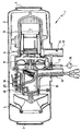
- the vehicle heater generally designated 1 in the figure is in the present example trained as an air heater. However, are equally good for the present invention Suitable for vehicle heaters that are connected to the cooling water circuit of a vehicle are.
- the vehicle heater 1 comprises a housing 2 with two end openings on one Entry side 3 and an exit side 4. Inside the housing 2 is from the entry side 3 to the outlet side 4 by means of a hot air blower 5 hot air via a heat exchanger 6 promoted for heating a vehicle interior, not shown.
- the one for warming of the heat exchanger 6 is the energy required by a burner 8 in one subsequent combustion chamber 7 extracted hot fuel gases.
- the burner 8 is Fuel from a fuel pump 16 via a fuel line 9 and combustion air fed by means of a blower 11.
- the resulting fuel-air mixture becomes ignited by means of an ignition device, not shown, and the resulting hot Exhaust gases leave the after heating the heat exchanger 6 via an exhaust pipe 13 Heater 1.
- the combustion air delivered by the blower 11 is fed through an intake manifold 12 sucked in.
- the combustion air blower 11 and the hot air blower 5 are operated by means of an electric motor 10 driven.
- the speed of this electric motor 10 can also be controlled by a control unit 18 like the frequency of the fuel pump 16.
- the components required to control the heater are in the control unit 18 on a circuit board 15 summarized.
- the control unit 18 comprises a microprocessor, not shown, in which an analog / digital converter part is integrated, to which a measurement signal, for example a Voltage signal, a subsequent exhaust gas sensor 14 explained in more detail.
- a measurement signal for example a Voltage signal
- a subsequent exhaust gas sensor 14 explained in more detail.
- the Microprocessor is also connected to a data memory, also not shown, in data is written in and data can be read from.
- setpoints are stored which correspond to the regulation of the Serve fuel / air mixture.
- the microprocessor of the control unit 18 controls via corresponding ones Outputs the speed of the fan 11 and the speed or the clock frequency the fuel pump. For subsequent adjustments or maintenance of the control unit 18 To enable a cover 25 is provided, after removal of which the control device 18 is accessible.
- the exhaust gas sensor 14 is designed either as a CO 2 sensor, CO sensor or as an O 2 sensor.
- the exhaust gas sensor of the heater 1 which is installed in the exhaust port of the heater 1, the wiring to the control unit 18 integrated within the heater 1 not being shown, measures the CO 2 , CO or O 2 content in the exhaust gas of the heater 1
- the output signal of the exhaust gas sensor 14 can be a current or a voltage value which, as stated above, is converted into a digital signal in the analog / digital converter part of the control unit 18 and is evaluated in the control unit 18. This evaluation effects control interventions, for example in a fuel pump 16, the heating air blower 5, the ignition device and the like.
- a typical control sequence according to the method according to the invention for operating of an engine independent vehicle heater 1 is as follows.
- the exhaust gas sensor 14 is activated together with a switch-on pulse for switching on the heater 1. Thereupon a safety circuit in the control unit 18 first checks whether the exhaust gas sensor 14 delivers a logically reasonable signal immediately following the switch-on pulse (plausibility check). In the event that the exhaust gas sensor 14 is a CO or CO 2 sensor, a reasonable signal or a plausible value is: 0% CO 2 or CO; the corresponding plausible value in the case of an O 2 sensor would be 21%, for example, since the heater 1 is not yet working.
- a so-called start pattern runs, which also includes a so-called safety time for fuel delivery.
- the flame forms in the heater within this safety time, as a result of which the abovementioned CO 2 or O 2 value of the exhaust gas, measured by the exhaust gas sensor 14 in the exhaust pipe 13 of the heater, is> 0% in the case of a CO or CO 2 measurement and assumes ⁇ 21% in the case of an O 2 measurement, and a corresponding current or voltage value is transmitted to the control unit 18.
- the measures known per se are taken by the control unit 18, such as switching off the ignition source, raising a load level and the like.
- the CO 2 value or the O 2 value measured by the exhaust gas sensor 14 in the exhaust pipe 13 of the heater 1
- the flame can be destabilized, with renewed measures to stabilize the flame, namely switching on the ignition source, lowering the load level and the like.
- a corresponding control cycle is carried out until there is flame stability, namely agreement between the actual and target value of the CO 2 or O 2 content in the exhaust gas. Now the flame is taken over.
- the flame transfer by recognizing the specified target value is followed by a continuous regulation of the combustion air and / or fuel quantity in order to constantly achieve an optimal, uniform combustion state of the heater 1.
- a corresponding optimal CO or CO 2 setpoint or O 2 setpoint of, for example, 12% CO 2 or 4.5% O 2 , on which the corresponding actual value is adjusted in a manner known per se.
- the control unit 18 keeps the CO, CO 2 and the O 2 value constant, as monitored by the exhaust gas sensor 14, when the setpoint and actual value match during the further course of the combustion.
- This CO, CO 2 or O 2 control achieves an optimal combustion state, which is also maintained in the event of fluctuations in environmental influences, such as different local heights above sea level. Furthermore, there is no need for a factory-set CO 2 or O 2 setting, as was previously required, since component tolerances of the combustion air blower or the fuel pump are compensated for by regulating the CO 2 value or O 2 value of the exhaust gas.
- the method according to the invention also provides an accident detection cycle, which Heater 1 switches off when the optimal, even combustion state is caused by a predetermined maximum number of control steps during the aforementioned continuous Regulation is not reached.
Landscapes
- Engineering & Computer Science (AREA)
- Mechanical Engineering (AREA)
- Chemical & Material Sciences (AREA)
- Combustion & Propulsion (AREA)
- General Engineering & Computer Science (AREA)
- Physics & Mathematics (AREA)
- Thermal Sciences (AREA)
- Air-Conditioning For Vehicles (AREA)
Abstract
Description
- 1
- Heizgerät
- 2
- Gehäuse
- 3
- Eintrittsseite
- 4
- Austrittsseite
- 5
- Heizluftgebläse
- 6
- Wärmetauscher
- 7
- Brennkammer
- 8
- Brenner
- 9
- Brennstoffleitung
- 10
- Elektromotor
- 11
- Gebläse
- 12
- Ansaugstutzen
- 13
- Abgasstutzen
- 14
- Abgassensor
- 15
- Platine
- 16
- Brennstoffpumpe
- 18
- Steuergerät
- 25
- Deckel
Claims (9)
- Verfahren zum Betreiben eines motorunabhängigen Fahrzeug-Heizgeräts (1), bei dem einem Brenner (8) durch eine Dosiereinrichtung (Brennstoffpumpe 16) Brennstoff und durch eine Fördereirrichtung (11) Brennluft zugeführt wird, bei dem die Flamme des Brenners (8) überwacht wird, und bei dem die Brennluft- und/oder Brennstoffmenge durch ein Steuergerät (18) geregelt wird, dadurch gekennzeichnet, daß ein im Abgasstrom durch einen Abgassensor (14) erfaßter Abgaswert zur Regelung der Brennluft- und/oder Brennstoffmenge (optimaler gleichmäßiger Verbrennungszustand des Heizgeräts) in das Steuergerät (18) eingegeben wird, und daß dieser Abgaswert im Steuergerät (18) außerdem zur Überwachung bzw. Stabilisierung der Flamme des Brenners (8) ausgewertet wird.
- Verfahren nach Anspruch 1, dadurch gekennzeichnet, daß der Abgassensor (14) als CO2-Sensor, CO-Sensor oder als O2-Sensor ausgebildet ist.
- Verfahren nach Anspruch 1 oder 2, dadurch gekennzeichnet, daß beim Einschalten des Heizgeräts (1) vor Beginn der Regelung der Brennluft- und/oder Brennstoffmenge eine Sicherheitsüberprüfung durchgeführt wird, bei der der vom Abgassensor (14) erfaßte Abgaswert auf Plausibilität (z.B. MeßwertNull
 vor Einleitung der Verbrennung) geprüft wird.
- Verfahren nach Anspruch 3, dadurch gekennzeichnet, daß sich an die Sicherheitsüberprüfung ein Sicherheitszeitintervall anschließt, während welchem die Brennstoff-Förderung eingeregelt und die Flamme im Brenner (8) unter zyklischer Überwachung der Flamme stabilisiert wird.
- Verfahren nach Anspruch 4, dadurch gekennzeichnet, daß der vom Abgassensor (14) erfaßte Abgaswert zur Überwachung der Flamme zu einem Sollwert in Bezug gesetzt wird, der einer stabil ausgebildeten Flamme entspricht, und daß durch das Steuergerät zur Stabilisierung der Flamme ein Ist-/Sollwert-Regelzyklus für die Flammenstabilität betreffende Parameter (z.B. Einschalten einer Zündquelle, Herunterfahren einer Laststufe und dgl.) bis zur Flammübernahme ausgeführt wird.
- Verfahren nach Anspruch 5, dadurch gekennzeichnet, daß sich an die Flammübernahme eine kontinuierliche Regelung der Brennluft- und/oder Brennstoffmenge zur konstanten Erzielung des optimalen gleichmäßigen Verbrennungszustands des Heizgeräts (1) anschließt.
- Verfahren nach Anspruch 6, dadurch gekennzeichnet, daß die Meßwerte des Abgassensors (14) zur Störfallerkennung herangezogen werden.
- Verfahren nach Anspruch 7, dadurch gekennzeichnet, daß ein Störfall-Erkennungszyklus vorgesehen ist, der eine Abschaltung des Heizgeräts (1) vorsieht, wenn der optimale gleichmäßige Verbrennungszustand durch eine vorgegebene Maximalzahl von Regelschritten nicht erreicht wird.
- Motorunabhängiges Fahrzeug-Heizgerät (1) mit einem Brenner (8), dem durch eine Dosiereinrichtung (16) Brennstoff und durch eine Fördereinrichtung (11) Brennluft zugeführt wird, mit einem Abgasstutzen (13) und mit einem Steuergerät (18) zur Regelung der Brennluft- und/oder Brennstoffmenge gemäß dem Verfahren nach einem der vorangehenden Ansprüche, gekennzeichnet durch einen auch der Flammüberwachung dienenden Abgassensor (14), der im Abgasstutzen (13) angeordnet ist und mit dem Steuergerät (18) in Signalverbindung steht.
Applications Claiming Priority (2)
| Application Number | Priority Date | Filing Date | Title |
|---|---|---|---|
| DE19636430A DE19636430C2 (de) | 1996-09-07 | 1996-09-07 | Verfahren und Vorrichtung zum Betreiben eines motorunabhängigen Fahrzeug-Heizgeräts |
| DE19636430 | 1996-09-07 |
Publications (3)
| Publication Number | Publication Date |
|---|---|
| EP0827854A2 true EP0827854A2 (de) | 1998-03-11 |
| EP0827854A3 EP0827854A3 (de) | 2002-07-03 |
| EP0827854B1 EP0827854B1 (de) | 2004-08-04 |
Family
ID=7804958
Family Applications (1)
| Application Number | Title | Priority Date | Filing Date |
|---|---|---|---|
| EP97114821A Expired - Lifetime EP0827854B1 (de) | 1996-09-07 | 1997-08-27 | Verfahren und Vorrichtung zum Betreiben eines motorunabhängigen Fahrzeug-Heizgeräts |
Country Status (2)
| Country | Link |
|---|---|
| EP (1) | EP0827854B1 (de) |
| DE (2) | DE19636430C2 (de) |
Cited By (6)
| Publication number | Priority date | Publication date | Assignee | Title |
|---|---|---|---|---|
| DE10144406C1 (de) * | 2001-09-10 | 2003-05-22 | Webasto Thermosysteme Gmbh | Heizgerät, insbesondere Zusatzheizgerät für mobile Anwendungen |
| EP1843096A2 (de) | 2006-04-04 | 2007-10-10 | J. Eberspächer GmbH Co. KG | Verfahren zum Betreiben eines brennstoffbetriebenen Fahrzeugheizgerätes |
| WO2008043347A1 (de) * | 2006-10-10 | 2008-04-17 | Webasto Ag | Regelung einer heizleistung eines heizgeräts |
| DE102007022938A1 (de) * | 2007-05-16 | 2008-11-20 | J. Eberspächer GmbH & Co. KG | Verfahren zur Flammüberwachung bei einem brennstoffbetriebenen Heizgerät |
| US20160061691A1 (en) * | 2014-09-01 | 2016-03-03 | Robert Bosch Gmbh | Method and device for diagnosing the function of an exhaust gas sensor |
| DE102022201665A1 (de) | 2022-02-17 | 2023-08-17 | Robert Bosch Gesellschaft mit beschränkter Haftung | Verfahren, Recheneinheit und Computerprogramm zur Diagnose der Funktionsfähigkeit eines Brenners |
Families Citing this family (6)
| Publication number | Priority date | Publication date | Assignee | Title |
|---|---|---|---|---|
| DE19945562B4 (de) * | 1999-09-23 | 2014-01-16 | Eberspächer Climate Control Systems GmbH & Co. KG | Verfahren zur Überwachung und/oder Regelung eines Fahrzeugheizgerätes |
| DE10153643A1 (de) * | 2001-10-31 | 2003-05-15 | Escube Space Sensor Systems Gm | Verfahren und Vorrichtung zur Überwachung und Optimierung einer Verbrennungsanlage |
| DE10210035A1 (de) * | 2002-03-07 | 2003-09-25 | Webasto Thermosysteme Gmbh | Mobiles Heizgerät mit einer Brennstoffzuführung |
| DE10226081B4 (de) * | 2002-06-12 | 2005-11-03 | J. Eberspächer GmbH & Co. KG | Wärmetauscheranordnung |
| DE102007020758B4 (de) * | 2007-05-03 | 2017-01-26 | Webasto Ag | Heizvorrichtung und Verfahren zur Brennstoffversorgung einer Heizvorrichtung |
| DE102024108018A1 (de) * | 2024-03-20 | 2025-09-25 | Truma Gerätetechnik GmbH & Co. KG | Heizgerät für ein Fahrzeug |
Family Cites Families (7)
| Publication number | Priority date | Publication date | Assignee | Title |
|---|---|---|---|---|
| DE2950689A1 (de) * | 1979-12-17 | 1981-06-25 | Servo-Instrument, in Deutschland Alleinvertrieb der BEAB-Regulatoren GmbH u. Co KG, 4050 Mönchengladbach | Regelvorrichtung fuer die verbrennungsluftmenge einer feuerstaette |
| DE3031410C2 (de) * | 1980-08-20 | 1985-01-03 | Webasto-Werk W. Baier GmbH & Co, 8035 Gauting | Steuergerät für Heizvorrichtungen |
| DE3807388A1 (de) * | 1988-03-07 | 1989-09-21 | Webasto Ag Fahrzeugtechnik | Verfahren zum betreiben eines heizgeraets und heizgeraet |
| GB2219403B (en) * | 1988-04-08 | 1992-05-20 | Telegan Ltd | Combustion monitor |
| DE4217150C2 (de) * | 1992-05-23 | 1996-02-15 | Webasto Thermosysteme Gmbh | Motorunabhängig betreibbares Fahrzeugheizgerät |
| US5366151A (en) * | 1993-12-27 | 1994-11-22 | Ford Motor Company | Hybrid vehicle fuel vapor management apparatus |
| DE4447285A1 (de) * | 1994-12-30 | 1996-07-04 | Eberspaecher J | Fahrzeugheizgerät |
-
1996
- 1996-09-07 DE DE19636430A patent/DE19636430C2/de not_active Expired - Lifetime
-
1997
- 1997-08-27 DE DE59711820T patent/DE59711820D1/de not_active Expired - Lifetime
- 1997-08-27 EP EP97114821A patent/EP0827854B1/de not_active Expired - Lifetime
Cited By (9)
| Publication number | Priority date | Publication date | Assignee | Title |
|---|---|---|---|---|
| DE10144406C1 (de) * | 2001-09-10 | 2003-05-22 | Webasto Thermosysteme Gmbh | Heizgerät, insbesondere Zusatzheizgerät für mobile Anwendungen |
| EP1843096A2 (de) | 2006-04-04 | 2007-10-10 | J. Eberspächer GmbH Co. KG | Verfahren zum Betreiben eines brennstoffbetriebenen Fahrzeugheizgerätes |
| EP1843096A3 (de) * | 2006-04-04 | 2009-09-02 | J. Eberspächer GmbH Co. KG | Verfahren zum Betreiben eines brennstoffbetriebenen Fahrzeugheizgerätes |
| WO2008043347A1 (de) * | 2006-10-10 | 2008-04-17 | Webasto Ag | Regelung einer heizleistung eines heizgeräts |
| DE102007022938A1 (de) * | 2007-05-16 | 2008-11-20 | J. Eberspächer GmbH & Co. KG | Verfahren zur Flammüberwachung bei einem brennstoffbetriebenen Heizgerät |
| US20160061691A1 (en) * | 2014-09-01 | 2016-03-03 | Robert Bosch Gmbh | Method and device for diagnosing the function of an exhaust gas sensor |
| US9995653B2 (en) * | 2014-09-01 | 2018-06-12 | Robert Bosch Gmbh | Method and device for diagnosing the function of an exhaust gas sensor |
| DE102022201665A1 (de) | 2022-02-17 | 2023-08-17 | Robert Bosch Gesellschaft mit beschränkter Haftung | Verfahren, Recheneinheit und Computerprogramm zur Diagnose der Funktionsfähigkeit eines Brenners |
| US12331669B2 (en) | 2022-02-17 | 2025-06-17 | Robert Bosch Gmbh | Method, computing unit, and computer program for diagnosing the functionality of a burner |
Also Published As
| Publication number | Publication date |
|---|---|
| EP0827854A3 (de) | 2002-07-03 |
| DE19636430A1 (de) | 1998-07-02 |
| EP0827854B1 (de) | 2004-08-04 |
| DE59711820D1 (de) | 2004-09-09 |
| DE19636430C2 (de) | 2002-02-14 |
Similar Documents
| Publication | Publication Date | Title |
|---|---|---|
| EP0619197B1 (de) | Motorunabhängiges Fahrzeugheizgerät | |
| EP0827854B1 (de) | Verfahren und Vorrichtung zum Betreiben eines motorunabhängigen Fahrzeug-Heizgeräts | |
| DE4440900C2 (de) | Kraftstoff-Zuführeinrichtung für eine Brennkraftmaschine | |
| DE3031410A1 (de) | Steuergeraet zum betreiben von heizvorrichtungen | |
| EP3593047B1 (de) | Verfahren zur brenngasartenerkennung beim startvorgang eines brenngasbetriebenen heizgeräts und brenngasbetriebenes heizgerät | |
| DE2721168A1 (de) | Kombiniertes gasturbinen- und dampfturbinenkraftwerk | |
| EP1409855A1 (de) | Brennkraftmaschine mit sekundärluftaufladung und verfahren zur regelung des sekundärluftladers | |
| DE102019101191A1 (de) | Verfahren zur Regelung eines Gasgemisches unter Nutzung eines Gassensors und eines Gasgemischsensors | |
| EP1158149B1 (de) | Einrichtung zum Einstellen des Verbrennungsgas-Luft-Verhältnisses eines vorzugsweise stationären Gasmotors | |
| EP4060235B1 (de) | Verfahren zum betreiben eines heizgerätes mit elektronischem gas-luftverbund, und heizgerät | |
| EP3707433A1 (de) | Verfahren zur regelung eines brenngasbetriebenen heizgeräts | |
| EP0925434A1 (de) | System zum betreiben einer brennkraftmaschine insbesondere eines kraftfahrzeugs | |
| DE10109808C2 (de) | Verfahren und Vorrichtung zur Anpassung eines brennerbetriebenen Heizgerätes an ein Luft-Abgas-System | |
| DE102009023964B4 (de) | Verfahren zum Betrieb eines Zweitaktmotors | |
| DE19752839A1 (de) | Verfahren zum Steuern eines Heizgeräts | |
| DE3516340A1 (de) | Heissgasgenerator (gasturbinenanlage) | |
| DE4002803A1 (de) | Vorrichtung zum regeln der leerlaufdrehzahl einer brennkraftmaschine | |
| DE102015207672B3 (de) | Verfahren zur Regelung eines Kraftstofffördersystems | |
| DE60217052T2 (de) | Vorrichtung und Verfahren zur Regelung eines Turboladers einer Brennkraftmaschine | |
| EP1934528B1 (de) | Verfahren und vorrichtung zur überwachung sich bildender ablagerungen von feststoffteilchen, insbesondere in einer brennstoffleitung sowie in den brennstoffventilen einer gasturbine | |
| DE102019101189A1 (de) | Verfahren zur Regelung eines Gasgemisches | |
| DE19627759C2 (de) | Brennstoffregler für Turbo-Strahltriebwerke | |
| DE10056064B4 (de) | Verfahren zum Regeln eines Gasbrenners | |
| WO2008043347A1 (de) | Regelung einer heizleistung eines heizgeräts | |
| DE102004049905A1 (de) | Verfahren zur Steuerung eines Verbrennungs-Heizgerätes und Verbrennungs-Heizgerät für Kraftfahrzeuge |
Legal Events
| Date | Code | Title | Description |
|---|---|---|---|
| PUAI | Public reference made under article 153(3) epc to a published international application that has entered the european phase |
Free format text: ORIGINAL CODE: 0009012 |
|
| AK | Designated contracting states |
Kind code of ref document: A2 Designated state(s): AT BE CH DE DK ES FI FR GB GR IE IT LI LU MC NL PT SE |
|
| AX | Request for extension of the european patent |
Free format text: AL;LT;LV;RO;SI |
|
| PUAL | Search report despatched |
Free format text: ORIGINAL CODE: 0009013 |
|
| AK | Designated contracting states |
Kind code of ref document: A3 Designated state(s): AT BE CH DE DK ES FI FR GB GR IE IT LI LU MC NL PT SE |
|
| AX | Request for extension of the european patent |
Free format text: AL;LT;LV;RO;SI |
|
| 17P | Request for examination filed |
Effective date: 20021220 |
|
| AKX | Designation fees paid |
Designated state(s): DE FR GB SE |
|
| 17Q | First examination report despatched |
Effective date: 20030623 |
|
| GRAP | Despatch of communication of intention to grant a patent |
Free format text: ORIGINAL CODE: EPIDOSNIGR1 |
|
| GRAS | Grant fee paid |
Free format text: ORIGINAL CODE: EPIDOSNIGR3 |
|
| GRAA | (expected) grant |
Free format text: ORIGINAL CODE: 0009210 |
|
| AK | Designated contracting states |
Kind code of ref document: B1 Designated state(s): DE FR GB SE |
|
| REG | Reference to a national code |
Ref country code: GB Ref legal event code: FG4D Free format text: NOT ENGLISH |
|
| REG | Reference to a national code |
Ref country code: IE Ref legal event code: FG4D Free format text: GERMAN |
|
| REF | Corresponds to: |
Ref document number: 59711820 Country of ref document: DE Date of ref document: 20040909 Kind code of ref document: P |
|
| REG | Reference to a national code |
Ref country code: SE Ref legal event code: TRGR |
|
| GBT | Gb: translation of ep patent filed (gb section 77(6)(a)/1977) |
Effective date: 20040903 |
|
| REG | Reference to a national code |
Ref country code: IE Ref legal event code: FD4D |
|
| ET | Fr: translation filed | ||
| PLBE | No opposition filed within time limit |
Free format text: ORIGINAL CODE: 0009261 |
|
| STAA | Information on the status of an ep patent application or granted ep patent |
Free format text: STATUS: NO OPPOSITION FILED WITHIN TIME LIMIT |
|
| 26N | No opposition filed |
Effective date: 20050506 |
|
| REG | Reference to a national code |
Ref country code: FR Ref legal event code: TP |
|
| REG | Reference to a national code |
Ref country code: FR Ref legal event code: PLFP Year of fee payment: 20 |
|
| PGFP | Annual fee paid to national office [announced via postgrant information from national office to epo] |
Ref country code: DE Payment date: 20160823 Year of fee payment: 20 Ref country code: GB Payment date: 20160824 Year of fee payment: 20 |
|
| PGFP | Annual fee paid to national office [announced via postgrant information from national office to epo] |
Ref country code: FR Payment date: 20160825 Year of fee payment: 20 Ref country code: SE Payment date: 20160823 Year of fee payment: 20 |
|
| REG | Reference to a national code |
Ref country code: DE Ref legal event code: R071 Ref document number: 59711820 Country of ref document: DE |
|
| REG | Reference to a national code |
Ref country code: GB Ref legal event code: PE20 Expiry date: 20170826 |
|
| REG | Reference to a national code |
Ref country code: SE Ref legal event code: EUG |
|
| PG25 | Lapsed in a contracting state [announced via postgrant information from national office to epo] |
Ref country code: GB Free format text: LAPSE BECAUSE OF EXPIRATION OF PROTECTION Effective date: 20170826 |