EP0827350A2 - Dispositif d'affichage d'images stéréoscopiques - Google Patents
Dispositif d'affichage d'images stéréoscopiques Download PDFInfo
- Publication number
- EP0827350A2 EP0827350A2 EP97115121A EP97115121A EP0827350A2 EP 0827350 A2 EP0827350 A2 EP 0827350A2 EP 97115121 A EP97115121 A EP 97115121A EP 97115121 A EP97115121 A EP 97115121A EP 0827350 A2 EP0827350 A2 EP 0827350A2
- Authority
- EP
- European Patent Office
- Prior art keywords
- horizontal
- image
- display device
- vertical
- cylindrical lens
- Prior art date
- Legal status (The legal status is an assumption and is not a legal conclusion. Google has not performed a legal analysis and makes no representation as to the accuracy of the status listed.)
- Withdrawn
Links
Images


Classifications
-
- G—PHYSICS
- G02—OPTICS
- G02B—OPTICAL ELEMENTS, SYSTEMS OR APPARATUS
- G02B30/00—Optical systems or apparatus for producing three-dimensional [3D] effects, e.g. stereoscopic images
- G02B30/20—Optical systems or apparatus for producing three-dimensional [3D] effects, e.g. stereoscopic images by providing first and second parallax images to an observer's left and right eyes
- G02B30/26—Optical systems or apparatus for producing three-dimensional [3D] effects, e.g. stereoscopic images by providing first and second parallax images to an observer's left and right eyes of the autostereoscopic type
- G02B30/27—Optical systems or apparatus for producing three-dimensional [3D] effects, e.g. stereoscopic images by providing first and second parallax images to an observer's left and right eyes of the autostereoscopic type involving lenticular arrays
-
- H—ELECTRICITY
- H04—ELECTRIC COMMUNICATION TECHNIQUE
- H04N—PICTORIAL COMMUNICATION, e.g. TELEVISION
- H04N13/00—Stereoscopic video systems; Multi-view video systems; Details thereof
- H04N13/30—Image reproducers
- H04N13/302—Image reproducers for viewing without the aid of special glasses, i.e. using autostereoscopic displays
- H04N13/305—Image reproducers for viewing without the aid of special glasses, i.e. using autostereoscopic displays using lenticular lenses, e.g. arrangements of cylindrical lenses
-
- H—ELECTRICITY
- H04—ELECTRIC COMMUNICATION TECHNIQUE
- H04N—PICTORIAL COMMUNICATION, e.g. TELEVISION
- H04N13/00—Stereoscopic video systems; Multi-view video systems; Details thereof
- H04N13/30—Image reproducers
- H04N13/302—Image reproducers for viewing without the aid of special glasses, i.e. using autostereoscopic displays
- H04N13/31—Image reproducers for viewing without the aid of special glasses, i.e. using autostereoscopic displays using parallax barriers
- H04N13/312—Image reproducers for viewing without the aid of special glasses, i.e. using autostereoscopic displays using parallax barriers the parallax barriers being placed behind the display panel, e.g. between backlight and spatial light modulator [SLM]
-
- H—ELECTRICITY
- H04—ELECTRIC COMMUNICATION TECHNIQUE
- H04N—PICTORIAL COMMUNICATION, e.g. TELEVISION
- H04N13/00—Stereoscopic video systems; Multi-view video systems; Details thereof
- H04N13/30—Image reproducers
- H04N13/302—Image reproducers for viewing without the aid of special glasses, i.e. using autostereoscopic displays
- H04N13/31—Image reproducers for viewing without the aid of special glasses, i.e. using autostereoscopic displays using parallax barriers
- H04N13/315—Image reproducers for viewing without the aid of special glasses, i.e. using autostereoscopic displays using parallax barriers the parallax barriers being time-variant
-
- H—ELECTRICITY
- H04—ELECTRIC COMMUNICATION TECHNIQUE
- H04N—PICTORIAL COMMUNICATION, e.g. TELEVISION
- H04N13/00—Stereoscopic video systems; Multi-view video systems; Details thereof
- H04N13/30—Image reproducers
- H04N13/302—Image reproducers for viewing without the aid of special glasses, i.e. using autostereoscopic displays
- H04N13/32—Image reproducers for viewing without the aid of special glasses, i.e. using autostereoscopic displays using arrays of controllable light sources; using moving apertures or moving light sources
-
- H—ELECTRICITY
- H04—ELECTRIC COMMUNICATION TECHNIQUE
- H04N—PICTORIAL COMMUNICATION, e.g. TELEVISION
- H04N13/00—Stereoscopic video systems; Multi-view video systems; Details thereof
- H04N13/30—Image reproducers
- H04N13/366—Image reproducers using viewer tracking
- H04N13/373—Image reproducers using viewer tracking for tracking forward-backward translational head movements, i.e. longitudinal movements
-
- H—ELECTRICITY
- H04—ELECTRIC COMMUNICATION TECHNIQUE
- H04N—PICTORIAL COMMUNICATION, e.g. TELEVISION
- H04N13/00—Stereoscopic video systems; Multi-view video systems; Details thereof
- H04N13/30—Image reproducers
- H04N13/366—Image reproducers using viewer tracking
- H04N13/376—Image reproducers using viewer tracking for tracking left-right translational head movements, i.e. lateral movements
-
- H—ELECTRICITY
- H04—ELECTRIC COMMUNICATION TECHNIQUE
- H04N—PICTORIAL COMMUNICATION, e.g. TELEVISION
- H04N13/00—Stereoscopic video systems; Multi-view video systems; Details thereof
- H04N13/30—Image reproducers
- H04N13/366—Image reproducers using viewer tracking
- H04N13/38—Image reproducers using viewer tracking for tracking vertical translational head movements
-
- H—ELECTRICITY
- H04—ELECTRIC COMMUNICATION TECHNIQUE
- H04N—PICTORIAL COMMUNICATION, e.g. TELEVISION
- H04N13/00—Stereoscopic video systems; Multi-view video systems; Details thereof
- H04N13/20—Image signal generators
- H04N13/204—Image signal generators using stereoscopic image cameras
- H04N13/207—Image signal generators using stereoscopic image cameras using a single 2D image sensor
- H04N13/218—Image signal generators using stereoscopic image cameras using a single 2D image sensor using spatial multiplexing
-
- H—ELECTRICITY
- H04—ELECTRIC COMMUNICATION TECHNIQUE
- H04N—PICTORIAL COMMUNICATION, e.g. TELEVISION
- H04N13/00—Stereoscopic video systems; Multi-view video systems; Details thereof
- H04N13/20—Image signal generators
- H04N13/204—Image signal generators using stereoscopic image cameras
- H04N13/239—Image signal generators using stereoscopic image cameras using two 2D image sensors having a relative position equal to or related to the interocular distance
-
- H—ELECTRICITY
- H04—ELECTRIC COMMUNICATION TECHNIQUE
- H04N—PICTORIAL COMMUNICATION, e.g. TELEVISION
- H04N13/00—Stereoscopic video systems; Multi-view video systems; Details thereof
- H04N13/20—Image signal generators
- H04N13/286—Image signal generators having separate monoscopic and stereoscopic modes
-
- H—ELECTRICITY
- H04—ELECTRIC COMMUNICATION TECHNIQUE
- H04N—PICTORIAL COMMUNICATION, e.g. TELEVISION
- H04N13/00—Stereoscopic video systems; Multi-view video systems; Details thereof
- H04N13/30—Image reproducers
- H04N13/324—Colour aspects
Definitions
- the present invention relates to a stereoscopic image display method and a stereoscopic image display apparatus using the method and, more particularly, to a stereoscopic image display apparatus capable of causing an observer to see a stereoscopic image within a wide observation region without using any special glasses.
- a lenticular lens or a parallax barrier is arranged on the surface of a liquid crystal display. For this reason, the image quality degrades due to surface reflection from the lens surface, or the black matrix of the liquid crystal display generates a Moiré, resulting in an eyesore.
- a stripe image must be combined by alternately arranging stripe pixels of two parallax images, and the combined image must be displayed. For this reason, the resolution of the stereoscopic image display apparatus is decreased to at least 1/2 that of the image display means.
- a stereoscopic image display apparatus solving these problems are disclosed in Japanese Laid-Open Patent Application Nos. 5-107663 and 7-234459.
- Figs. 22A to 22C are views showing the basic arrangement of the stereoscopic image display apparatus disclosed in Japanese Laid-Open Patent Application No. 5-107663.
- This apparatus comprises an optical directivity changing apparatus 101 having a matrix type surface illuminant 102 and a lenticular sheet 103, and a transmission type display apparatus 104. While a stripe light source (102R in Fig. 22B) for the right eye is turned on, an image (104R in Fig. 22C) for the right eye is displayed in an odd number frame. While a stripe light source (102L in Fig. 22B) for the left eye is turned on, an image (104L in Fig. 22C) for the left eye is displayed in an even number frame.
- the observer can see the stereoscopic image only within a range corresponding to a binocular center distance of about 65 mm. For this reason, the observer must fix the head position during observation, resulting in a difficulty in observation.
- a lenticular lens is supported to be movable in the horizontal direction, and the positions of the both eyes of the observer are detected.
- the lenticular lens is moved in the left-and-right direction relative to the display element in accordance with the detection result, thereby widening the stereoscopic image region.
- Japanese Laid-Open Patent Application No. 2-50145 proposes a scheme in which the positions of the eyes of the observer are detected, and the left and right positions of the display pixel portions of an image are replaced, thereby widening the stereoscopic image region.
- the critical frequency (critical fusion frequency CFF) at which no flicker is perceived when the left and right eyes are alternately closed is about 55 Hz. From the viewpoint of flicker, the field frequency must be at least 110 Hz.
- a display device capable of displaying an image at a high speed must be used as the transmission type display apparatus 104.
- the scheme of measuring the observer position to follow the movement of the observer can cope with only horizontal changes in observer position.
- crosstalk is generated to degrade the stereoscopic effect.
- a stereoscopic image display apparatus for causing an observer to observe a stereoscopic image, comprising:
- the apparatus further comprises a horizontal cylindrical lens array arranged between the mask pattern and the display device and constituted by horizontal cylindrical lenses each having a generatrix in the horizontal direction.
- the vertical cylindrical lens array converts a light beam emerging from one point of the aperture portion into a substantially collimated light beam in a horizontal section, and the horizontal cylindrical lens array substantially focuses the light beam emerging from one point of the aperture portion onto a predetermined position of the display device in a vertical section.
- An optical distance between the mask pattern and the vertical cylindrical lens array is set to be larger than a converted distance between the mask pattern and the horizontal cylindrical lens array.
- a vertical width of the aperture portion is made to correspond to a width of a plurality of scanning lines of the display device.
- a vertical width of a horizontal stripe pixel displayed on the display device is made equal to the width of the plurality of scanning lines of the display device, which corresponds to the vertical width of the aperture portion.
- a stereoscopic image display apparatus for causing an observer to observe a stereoscopic image, comprising:
- the vertical cylindrical lens array or the horizontal cylindrical lens array has plano-convex cylindrical lenses.
- a stereoscopic image display apparatus for causing an observer to observe a stereoscopic image, comprising:
- the light source means has a self-emission type display element having a discrete pixel structure.
- the light source means has means for forming a mask pattern including aperture portions and shielding portions arranged in a checkerboard pattern on a display surface of an optical modulator having a discrete pixel structure and illuminating the mask pattern with a surface illuminant.
- the apparatus further comprises a horizontal cylindrical lens array arranged between the light source means and the display device and constituted by horizontal cylindrical lenses each having a generatrix in the horizontal direction, wherein a light beam emerging from one point of the light-emitting portion is focused onto the display device as a caustic curve.
- L h2 a converted distance between the vertical cylindrical lens array and the light source means
- L h1 a converted distance between a predetermined observation position and the display device
- E a predetermined distance between eyes of the observer
- P h2 the horizontal pixel size of the display element
- the apparatus further comprises position detection means for detecting a position of the observer, a horizontal positional shift of the observer from a predetermined reference position is detected by the position detection means, and the light-emitting portions are moved in the horizontal direction in accordance with the positional shift.
- the light-emission pattern is formed by repeatedly arranging a unit in which a light-emitting portion and a non-emitting portion each having a predetermined size are repeated a predetermined number of times in the horizontal direction, and each of a plurality of light-emitting portions and non-emitting portions in the unit is constituted by one of at least two different numbers of pixels in the horizontal direction.
- a stereoscopic image display apparatus for causing an observer to observe a stereoscopic image, comprising:
- a stereoscopic image display apparatus for causing an observer to observe a stereoscopic image, comprising:
- the light source means has a self-emission type display element having a discrete pixel structure.
- the light source means has means for forming a mask pattern including aperture portions and shielding portions arranged in a checkerboard pattern on a display surface of an optical modulator having a discrete pixel structure and illuminating the mask pattern with a surface illuminant.
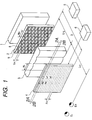
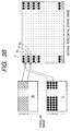
- Fig. 1 is a schematic perspective view of a stereoscopic image display apparatus according to the first embodiment of the present invention.
- Figs. 2A and 2B are explanatory views of the first embodiment.
- a section taken along a horizontal plane including a line A corresponds to Fig. 2A
- a section taken along a horizontal plane including a line B corresponds to Fig. 2B.
- the stereoscopic image display apparatus has a backlight source 1 and a mask 2.
- the mask 2 has, on its surface, a mask pattern 9 having predetermined aperture portions and shielding portions.
- the mask pattern 9 is formed by patterning chromium, chromium oxide, or a light-absorbing member such as a resin black matrix on a mask substrate consisting of glass, plastic, or the like.
- the mask 2 and the backlight source 1 constitute a light source means.
- a vertical lenticular lens (vertical cylindrical lens array) 3 is constituted by arranging a number of plano-convex vertical cylindrical lenses in the horizontal direction.
- the lens curvature of the vertical lenticular lens 3 is set such that the mask pattern 9 is located nearly at the focal point of each cylindrical lens of the vertical lenticular lens 3.
- a pair of an aperture portion 8 and a shielding portion arranged on the mask pattern 9 in the horizontal direction correspond to one pitch (width) H L of each vertical cylindrical lens of the vertical lenticular lens 3.
- a display device 4 is constituted by a transmission type liquid crystal element or the like.
- Figs. 2A and 2B schematically show the state of an image displayed on the image display screen.
- An image processing means 5 combines a stripe image from a plurality of parallax images.
- a display drive circuit 6 drives the display device 4 upon receiving a stripe image signal from the image processing means 5 to display a stripe image on the display device 4.
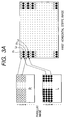
- Figs. 3A and 3B are explanatory views of stripe image combination.
- the image processing means 5 divides at least two parallax images, i.e., a right parallax image R and a left parallax image L into a number of horizontal stripe pixels and alternately arranges stripe pixels R i formed from the right parallax image R and stripe pixels L i formed from the left parallax image L on scanning lines.
- a right stripe pixel R 1 on the first scanning line, a left stripe pixel L 2 on the second scanning line, a right stripe pixel R 3 on the third scanning line,... are combined to form one horizontal stripe image (this horizontal stripe image will be referred to as the first horizontal stripe image).
- the image data of the horizontal stripe image prepared in the above way is input to the display drive circuit 6, so that the horizontal stripe image is displayed on the display device 4.
- Fig. 2A The function of displaying a stereoscopic image will be described next.
- light beams emitted from the backlight source 1 are transmitted through the mask 2 and separately focused and incident on a region where a right eye E R of the observer should be located through the mask pattern 9 on which the center of each aperture portion 8 is located at a position shifted from the optical axis of a corresponding cylindrical lens of the vertical lenticular lens 3 by a predetermined amount, and the vertical lenticular lens 3.
- the light beams incident on the right eye E R are modulated by the image (right stripe pixel R 1 formed from the right parallax image R) displayed on the display device 4 arranged between the vertical lenticular lens 3 and the observer, so that light beams which have passed through the linear right stripe pixel R 1 are incident on the right eye E R .
- the mask aperture portions on the section shown in Fig. 2A and those on the section shown in Fig. 2B are complementary. That is, the aperture and shielding portions of the mask pattern 9 are arranged in a checkerboard pattern.
- the display device 4 displays the horizontal stripe image obtained by alternately arranging the stripe pixels R i and L i corresponding to the respective aperture portions in the vertical direction and combining the stripe pixels.
- the observer sees, with the left and right eyes, stripe pixels corresponding to the respective eyes in units of scanning lines. Therefore, the left and right eyes can see corresponding parallax images, so that a stereoscopic image can be observed as a whole.
- the mask pattern 9 has an appropriate aperture ratio in the vertical direction such that the left and right stripe pixels constituting the stripe image are illuminated without crosstalk.
- Images such as CG images created on a computer, or a plurality of natural images taken by a dual-lens camera or a stereoscopic camera may be used as parallax images in this embodiment.
- the first horizontal stripe image is displayed.
- a horizontal stripe image (to be referred to as the second horizontal stripe image) formed by combining a left stripe pixel L 1 on the first scanning line, a right stripe pixel R 2 on the second scanning line, a left stripe pixel L 3 on the third scanning line,... may also be used, as shown in Fig. 3B.
- the aperture portions of the mask pattern 9 in use of the first horizontal stripe image shown in Fig. 3A may be shifted to the right or left by H m /2.
- the scanning lines of the display device 4 may be shifted upward or downward by one line.
- each optical element The formation conditions of each optical element will be described.
- a converted distance is used for the distance between optical elements.
- the converted distance is a so-called optical distance obtained by converting the distance between two optical elements into a value in the air using, as reference points, the display surface of the display device, the surface of the mask on which the mask pattern 9 is formed, and the principal point on the target distance measurement side of the lenticular lens.
- the reference points of an optical modulator and a self-emission type display element in embodiments to be described later are the display surface and the light-emission surface, respectively.
- the converted distance between the vertical lenticular lens 3 and the mask pattern 9 (optical interval obtained by converting the distance between the mask-side principal point of the vertical lenticular lens 3 and the mask pattern 9 into a value in the air) is represented by L h2 ; the distance from a predetermined observation position to the vertical lenticular lens 3 (optical interval obtained by converting the distance between the observation position and the observer-side principal point of the vertical lenticular lens 3 into a value in the air), L h1 ; a predetermined distance between the eyes of the observer, E; the horizontal width (pitch) of a pair of an aperture portion and a shielding portion arranged on the mask pattern 9 in the horizontal direction, H m ; and the pitch (width) of each vertical cylindrical lens of the vertical lenticular lens 3, H L .
- the vertical width of the aperture portion 8 of the mask pattern 9 is represented by V m ; the vertical width of the stripe pixel of the display device 4 (in this case, this width corresponds to the scanning line width), P V1 ; and the converted distance between the mask 2 and the display device 4 (optical interval obtained by converting the distance between the mask pattern 9 and the display surface of the display device 4 into a value in the air), D.
- V m P V1 ⁇ L h1 ( L h1 - D )
- Fig. 13 is a side view of the vertical section of this embodiment.
- the observation region in the vertical direction will be described with reference to Fig. 13.
- the aperture portions 8 formed on the mask 2 are arranged in a checkerboard pattern, as shown in Fig. 1.
- the aperture portions 8 correspond, in the vertical direction, to the right or left stripe pixels of the horizontal stripe image displayed on the display device 4.
- the plurality of aperture portions 8 shown in Fig. 13 correspond to right stripe pixels.
- P V2 corresponds to 1/2 the vertical pitch of the aperture portion of the mask pattern 9.
- Half of the vertical pitch P V2 of the aperture portions, i.e., 1/2P V2 is set to be slightly larger than the vertical width P V1 of the stripe pixel of the horizontal stripe image. For this reason, the observer located at a position separated from the display device 4 by a predetermined observation distance can observe the corresponding aperture portions through the stripe pixels displayed on the display device 4. When the eyes of the observer are set at a predetermined height, an observation region where the left and right images can be uniformly separately observed over the total vertical width of the screen can be obtained.
- the vertical width V m of the aperture portion 8 of the mask pattern 9 is set to be smaller than the width P V1 of the stripe pixel, and the vertical width V m of the aperture portion 8 is set to be smaller than the vertical width V m ' of the shielding portion.
- the above function can be realized by setting 1/2 the vertical pitch P V2 of the aperture portion of the mask pattern 9 to be slightly larger than the vertical width P V1 of the stripe pixel displayed on the display device 4 to adjust the vertical aperture ratio of the aperture portion 8.
- a liquid crystal element having an RGB vertical stripe pixel array whose pixel pitch is 0.111 mm (horizontal) x 0.33 mm (vertical) is used as the display device 4.
- L h1 is 500 mm
- L h2 is 5 mm
- E is 65 mm
- H m /2 is 0.65 mm
- H L is 1.287 mm.
- the horizontal width H m /2 of the aperture portion 8 equals the width of about six pixels (two picture elements) of the display device 4.
- the lens pitch H L of the vertical lenticular lens 3 can be increased to 1.287 mm. This facilitates the manufacture of the optical elements and allows cost reduction.
- a display device whose vertical pixel size is 0.33 mm is used, and D is set at about 6 mm. Therefore, P V1 is 0.33 mm, and the vertical width V m of the aperture portion of the mask pattern 9 is 0.334 mm.
- the mask pattern 9 and the vertical lenticular lens 3 are used to control the directivity of light beams emitted from the backlight source 1.
- the horizontal stripe image to be displayed on the display device 4 is combined from the left and right parallax images in units of scanning lines.
- the left and right stripe pixels constituting the horizontal stripe image are illuminated without crosstalk, and the light beams are made incident on the eyes of the observer. With this arrangement, the display rate (frame rate) of the display device 4 need not be increased.
- the horizontal stripe image can be combined from the left and right parallax images in units of scanning lines, the horizontal pixel arrangement of the display device 4 is not restricted.
- a liquid crystal element using vertical stripe color filters is used as the display device 4, a color stereoscopic image can be easily displayed.
- the vertical lenticular lens 3 and the mask 2 are arranged behind the display device 4 for displaying an image when viewed from the observer side, thereby giving directivity to illumination light.
- no high-contrast Moiré is generated by surface reflection on the vertical lenticular lens 3 or the black matrix of the display device 4 constituted by the liquid crystal element.
- the vertical lenticular lens 3 formed by plano-convex vertical cylindrical lenses is used as a vertical cylindrical lens array.
- a cylindrical lens array having appropriate curvatures on both sides may be used to substantially focus light beams from the backlight source 1 to the respective eyes.
- chromium, chromium oxide, or a light-absorbing member such as a resin black matrix is to be patterned on a glass or plastic substrate to form the mask pattern 9
- a high-reflection member of chromium or aluminum may be formed on the surface on the side of the backlight source 1
- a low-reflection member of chromium oxide or the light-absorbing member such as a resin black matrix may be formed on the resultant structure.
- Fig. 4 is a schematic perspective view of a stereoscopic image display apparatus according to the second embodiment of the present invention.
- the aperture ratio associated with the vertical direction of the mask pattern 9 is appropriately adjusted to illuminate the left or right stripe pixels constituting the horizontal stripe image without any crosstalk.
- a horizontal lenticular lens 7 having an imaging function in the vertical direction is added to the first embodiment.
- a predetermined pixel (one scanning line in the embodiment) of a display device 4 is illuminated without any crosstalk with light beams emerging from the aperture portions of a mask pattern 9.
- the horizontal lenticular lens 7 (horizontal cylindrical lens array) is constituted by arranging a lot of plano-convex horizontal cylindrical lenses in the vertical direction. The function of the horizontal lenticular lens 7 will be described later.
- light beams emerging from aperture portions 8 of the mask pattern 9 and extending in the vertical direction are condensed on a predetermined stripe pixel on the display device 4 to illuminate on the stripe pixel.
- the light beams are transmitted through the stripe pixel and diverge only in the vertical direction in accordance with the NA in focusing.
- the eyes of the observer are set at a predetermined height, an observation region where the left and right images can be uniformly separately observed over the total vertical width of the screen can be obtained.
- the function of this embodiment will be described. Since the horizontal lenticular lens 7 has no optical power in the horizontal direction, the function of this embodiment associated with the horizontal direction is the same as that of the first embodiment. More specifically, the display device 4 displays the same horizontal stripe image as in the first embodiment. Light beams from a backlight source 1 are transmitted through the aperture portions 8 of the mask pattern 9 to illuminate the display device 4 through a vertical lenticular lens 3. The light beams are focused while separating left and right stripe pixels into the left and right eye regions of the observer, respectively, thereby allowing the observer to see the left and right parallax images.
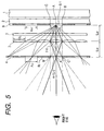
- Fig. 5 is a sectional view for explaining the function of the vertical section of the second embodiment. The observation region in the vertical direction will be described with reference to Fig. 5.
- the aperture portions of the mask pattern 9 are arranged in a checkerboard pattern, as shown in Fig. 4. The aperture portions correspond, in the vertical direction, to the respective stripe pixels of the horizontal stripe image displayed on the display device 4.
- the aperture portions of the mask pattern 9 shown in Fig. 5 are to illuminate the stripe pixels for the right or left eye of the observer.
- Stripe pixels (L i ) for the left eye of the observer are illuminated.
- the left stripe pixels of the display device 4, which correspond to the left eye, are represented by blank portions, and the right stripe pixels corresponding to the right eye are represented by hatched portions.
- Equation (3) defines that the image of light from the aperture portion is formed on a corresponding image line (e.g., an image line for the right eye) on the display device 4. If this relationship has an error, the illumination light illuminates an image line (e.g., an image line for the left eye) which does not correspond to the aperture portion, resulting in crosstalk. Since the error of equation (3) is almost proportional to the crosstalk amount, the error of equation (3) is preferably smaller than the allowance of crosstalk, e.g., 5% or less.
- Equation (4) defines that the image of light beams from a plurality of aperture portions corresponding to one eye (e.g., right eye) is formed on a plurality of corresponding image lines (e.g., image lines for the right eye) on the display device 4 independently of the cylindrical lenses of the horizontal lenticular lens through which the light beams are transmitted. If this relationship has an error, the position of an illumination line extending in the horizontal direction is cumulatively shifted in the vertical direction on the display device 4. Image lines (e.g., image lines for the left eye) which do not correspond to the aperture portions are illuminated at the upper and lower end of the screen, resulting in crosstalk. Errors in equation (4) are accumulated as the number of image lines increases.
- the allowance of the error changes depending on the number of pixels in the vertical direction of the screen.
- the number of pixels in the vertical direction is 480.
- the allowance is about 1/240, i.e., only about 4%.
- Equation (5) defines the focal length of the cylindrical lens for forming the image of the mask pattern on the display surface.
- a shift of the focal length f V blurs the illumination line, resulting in crosstalk.
- a light beam incident on each cylindrical lens of the lenticular lens is thin, and the increase in illumination line width due to defocusing is relatively small.
- equations (3) and (4) hold, a light beam passing through the center of each cylindrical lens propagates to a predetermined position even when equation (5) has an error, so that the light beam is irradiated almost on the predetermined portion.
- the error allowance of equation (5) is about 15% for the numerical example shown in Table 1 (to be described later).
- Light beams emerging from the point A at the center of the aperture portion 8-1 and incident on horizontal cylindrical lenses, other than the horizontal cylindrical lens 7-1, of the horizontal lenticular lens 7, are focused on the centers of stripe pixels for the left eye, other than the stripe pixel 4-1, as caustic curves.
- Light beams emerging from other points of the aperture portion 8-1 and incident on the horizontal cylindrical lens 7-1 are focused at corresponding positions on the stripe pixel 4-1 as caustic curves.
- All light beams emerging from the aperture portion 8-1 and incident on horizontal cylindrical lenses other than the horizontal cylindrical lens 7-1 are also condensed on image lines for displaying the stripe pixels for the left eye on the display device 4.
- equations (3), (4), and (5) may be satisfied.
- the converted distance L V2 between the horizontal lenticular lens 7 and the mask pattern 9 can be arbitrarily set.
- the vertical lenticular lens 3 can be arranged/set independently of the characteristics of the horizontal lenticular lens 7 as far as the vertical lenticular lens 3 does not physically interfere with the remaining members.
- the distance L h2 between the mask pattern 9 and the vertical lenticular lens 3 can be arbitrarily increased. Therefore, as is apparent from equation (1), the width of a pair of an aperture portion and a shielding portion of the mask pattern 9 can be increased.
- Fig. 6 is a schematic perspective view of a stereoscopic image display apparatus according to the third embodiment of the present invention.
- the third embodiment is different from the second embodiment in the arrangement positions of a vertical lenticular lens 3 and a horizontal lenticular lens 7. More specifically, the positions of the two lenticular lenses of the second embodiment are replaced.
- the specifications of members are set such that equations (1) to (5) described above are established.
- the vertical optical function and the horizontal optical function are independent.
- both a converted distance L V1 between the horizontal lenticular lens 7 and a display device 4 and a converted distance L V2 between the horizontal lenticular lens 7 and the mask pattern 9 must be set to be larger than the converted distance L h2 .
- the converted distance (L V1 +L V2 ) between the mask pattern 9 and the display device 4 is larger than twice the distance L h2 , so that the apparatus tends to be thick.
- the vertical lenticular lens 3 is separated from the mask pattern 9 by a distance larger than that between the mask pattern 9 and the horizontal lenticular lens 7.
- the converted distance between the mask pattern 9 and the display device 4 can be made almost equal to the converted distance L h2 between the mask pattern 9 and the vertical lenticular lens 3, so that the thickness of the entire apparatus can be reduced.
- the apparatus when the apparatus is arranged to satisfy conditions (1) to (5) independently of the arrangement order of the vertical and horizontal lenticular lenses, the effect as described above can be obtained. This is because the vertical optical function and the horizontal optical function are independent, as described above.
- Fig. 7 is a schematic perspective view of a stereoscopic image display apparatus according to the fourth embodiment of the present invention.
- the left and right parallax images are divided in units of scanning lines, a horizontal stripe image is combined and displayed on the display device 4, and light beams transmitted through the respective stripe pixels are made incident on the eyes of the observer.
- the left and right parallax images are divided into stripe pixels by the width of a plurality of scanning lines (in this case, the width of three scanning lines). These stripe pixels are alternately arranged to combine the horizontal stripe image, and the horizontal stripe image is displayed on a display device 4.
- the principle of stereoscopic image display and the arrangement conditions of the apparatus are the same as those in the third embodiment, and a detailed description thereof will be omitted. Only different portions will be described below.
- the left and right parallax images are divided into stripe pixels by the width of three scanning lines on the display device 4.
- the left and right stripe pixels are alternately arranged from the upper end of the screen to combine a horizontal stripe image, and the horizontal stripe image is displayed on the display device 4.
- a vertical width P V1 of a stripe pixel becomes three times that of the above-described embodiments.
- a vertical width V m of an aperture portion of a mask pattern 9 and a pitch V L of each horizontal cylindrical lens of a horizontal lenticular lens 7, which are determined from equations (3) and (4), respectively, can be increased relative to those of the above embodiments.
- the pitches of the mask pattern 9 and the horizontal lenticular lens 7 can be increased, these optical elements can be easily manufactured, and the cost of the apparatus can be reduced.
- At least two parallax images R and L are divided into horizontal stripe pixels each having the width of three scanning lines by an image processing means 5 (not shown).
- Right stripe pixels R i prepared from the right parallax image R and left stripe pixels L i prepared from the left parallax image L, each of which has the width of three scanning lines, are alternately arranged.
- a right stripe pixel R 1 is arranged at the position from a first scanning pixel S 1 to a third scanning pixel S 3 , a left stripe image L 2 at the position from a fourth scanning pixel S 4 to a sixth scanning pixel S 6 , a right stripe pixel R 3 at the position from a seventh scanning pixel S 7 to a ninth scanning pixel S 9 ,... to combine one horizontal stripe image (to be referred to as the first horizontal stripe image).
- the image data of the horizontal stripe image prepared in the above manner is input to a display drive circuit 6 (not shown).
- the horizontal stripe image is displayed on the display device 4, so that a stereoscopic image can be displayed on the basis of the same principle as described above.
- the left and right stripe pixels may be replaced and arranged in the order of L 1 , R 2 , L 3 , R 4 , L 5 , R 6 , L 7 ,... to combine a second horizontal stripe image, as described in Fig. 3.
- a mask pattern having aperture portions and shielding portions which are complementary to those of the mask pattern 9 used for the first horizontal stripe image (R 1 , L 2 , R 3 , L 4 , R 5 , L 6 ...) shown in Fig. 7 may be used.
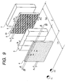
- Fig. 9 is a schematic perspective view of a stereoscopic image display apparatus according to the fifth embodiment of the present invention.
- the mask 2 of the first embodiment is changed to an optical modulator, and a mask pattern is formed on the display surface of the optical modulator.
- the remaining arrangements are the same as those of the first embodiment. Different points will be mainly described below.
- an optical modulator 20 has a discrete pixel structure.
- the optical modulator 20 is constituted by a monochromatic transmission type liquid crystal display element, and a mask pattern 9 having a number of rectangular aperture portions is formed on the display surface of the optical modulator 20.
- the mask pattern 9 is illuminated with a backlight source 1.
- the optical modulator 20 and the backlight source 1 constitute a light source means.
- a horizontal stripe image formed from stripe pixels each having the width of one scanning line is displayed on a display device 4, as in the first embodiment.
- Light beams from the backlight source 1 are transmitted through aperture portions 8 (blank portions in Fig. 9) of the mask pattern 9 formed on the optical modulator 20 and illuminate the display device 4 through a vertical lenticular lens (vertical cylindrical lens array) 3.
- the light beams are separated into light beams having information of right stripe pixels and light beams having information of left stripe pixels and condensed on predetermined regions, so that the left and right parallax images are separately observed with the eyes of the observer, which are located in these regions.
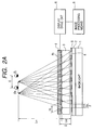
- Fig. 10 is a sectional view for explaining the function of the horizontal section of the fifth embodiment.
- the optical modulator 20 is illuminated with the backlight source 1, and light beams emerge from the aperture portions 8.
- the lens curvature of the vertical lenticular lens 3 is set such that the mask pattern 9 is located nearly at the focal position of each vertical cylindrical lens of the vertical lenticular lens 3.
- the mask pattern 9 need not be strictly located at the focal position of each vertical cylindrical lens and may be set within a range where light beams emerging from the aperture portions to form the left and right image regions do not mix at the observation position to cause crosstalk.
- a horizontal width (pitch) H m of a pair of an aperture portion and a shielding portion arranged in the horizontal direction on the mask pattern 9 corresponds to a pitch H L of a vertical cylindrical lens of the vertical lenticular lens 3.
- the pattern of the aperture portion and the shielding portion shown in Fig. 10 corresponds to a right stripe pixel of the horizontal stripe image displayed on the display device 4.
- Light beams emerging from the aperture portions 8 are transmitted through the vertical lenticular lens 3 and illuminate the right stripe pixel with directivity in the range indicated by solid lines in Fig. 10.
- E R in Fig. 10 represents the right eye of the observer.
- H L the horizontal width of one vertical cylindrical lens of the vertical lenticular lens 3
- H m the width (pitch) of a pair of an aperture portion and a shielding portion arranged in the horizontal direction on the mask pattern 9, H m
- L h2 the width of the mask pattern 9 and the vertical lenticular lens 3
- L h1 the vertical lenticular lens 3
- E equations (1) and (2) hold among these specifications.
- the right stripe pixels of the horizontal stripe image displayed on the display device 4 are observed only within a range indicated by an arrow, where the right eye E R is present.
- the pattern of the aperture portions and the shielding portions of the mask pattern 9 is reversed to that shown in Fig. 10, so that the aperture portions and the shielding portions correspond to a left stripe pixel in the horizontal stripe image displayed on the display device 4.
- Light beams transmitted through the vertical lenticular lens 3 and the left stripe pixels are focused with directivity on a region shifted by the distance E between the eyes in the horizontal direction from the region where light beams for illuminating the right stripe pixels are condensed.
- the left and right stripe pixels are separated into the left and right eyes in the horizontal direction and observed.
- the left parallax image is observed by the left eye, and the right parallax image is observed by the right eye as sets of stripe pixels, so that a stereoscopic image can be observed.
- the distance along the front-and-rear direction from the apparatus to the observer is reduced and emphasized to describe the stereoscopic image displaying method of this embodiment (the distance L h2 is illustrated at a ratio much larger than that of the distance L h1 ).
- the pitch H m is illustrated to be much larger than the pitch H L .
- the pitch H m becomes slightly larger than the pitch H L in accordance with equation (2).
- P h2 represents the horizontal size of one pixel of the optical modulator 20.
- four pixels of the optical modulator 20 constitute a pair of an aperture portion and a shielding portion.
- Four pixels 9a of the optical modulator 20 correspond to a vertical cylindrical lens 3a of the vertical lenticular lens 3.
- Four pixels 9b and 9c of the optical modulator 20 correspond to vertical cylindrical lenses 3b and 3c, respectively.
- Fig. 11 is a sectional view of the display unit and light beams, which are illustrated at a ratio close to the actual design values.
- Fig. 12 is a view for explaining focusing of light beams near the observation plane.
- the same reference numerals as in Fig. 10 denote the same members in Fig. 11.
- the four pixels 9a of the optical modulator 20 correspond to the vertical cylindrical lens 3a of the vertical lenticular lens 3
- the four pixels 9b and 9c of the optical modulator 20 correspond to the cylindrical lenses 3b and 3c, respectively.
- the vertical lenticular lens 3 has a lot of vertical cylindrical lenses arranged in the horizontal direction in addition to the vertical cylindrical lenses 3a to 3c.
- Each vertical cylindrical lens corresponds to a pair of an aperture portion formed by two pixels and a shielding portion formed by two pixels, i.e., a total of four pixels. Directivity is given to light beams from the aperture portions by the vertical cylindrical lenses such that the light beams are condensed on the right-eye region of the observation plane.
- Fig. 12 shows a state wherein light beams to which directivity is given by the vertical lenticular lens 3 are focused on the region where the right eye E R of the observer is present on the observation plane.
- Right stripe pixels constituting the horizontal stripe image displayed on the display device 4 are observed only within a range indicated by an arrow where the right eye E R is present.
- Fig. 13 is a sectional view for explaining the function of the vertical section of this embodiment. The observation region in the vertical direction will be described with reference to Fig. 13.
- the aperture portions formed on the optical modulator 20 are arranged in a checkerboard pattern, as shown in Fig. 9.
- the aperture portions correspond, in the vertical direction, to right stripe pixels or left stripe pixels of the horizontal stripe image displayed on the display device 4. All the plurality of aperture portions 8 shown in Fig. 13 correspond to right stripe pixels.
- P V2 represents the vertical pixel size of the optical modulator.
- the aperture portion 8 is set to an appropriate aperture ratio in one pixel using a non-transmission portion of a black matrix or the like.
- the vertical pixel size P V2 of the optical modulator 20 is slightly larger than a vertical width P V1 of a stripe pixel of the horizontal stripe image.
- the observer separated from the display device 4 by a predetermined observation distance can observe corresponding aperture portions through stripe pixels displayed on the display device 4. Therefore, when the eyes of the observer are set at a predetermined height, an observation region where the left and right images can be uniformly separately observed over the total vertical width of the screen can be obtained.
- a vertical width V m of the aperture portion 8 of the mask pattern 9 is made smaller than the vertical width P V1 of a stripe pixel, and the vertical width V m of the shielding portion 8 is made smaller than a vertical width V m ' of a shielding portion.
- the above function can be realized by constituting each of the aperture portions and the shielding portions of the mask pattern 9 by one pixel of the optical modulator 20 along the vertical direction and setting the vertical width P V2 of a pixel of the optical modulator 20 to be slightly larger than the vertical width P V1 of a stripe pixel displayed on the display device 4 to adjust the vertical aperture ratio of the pixels of the optical modulator 20.
- an LCD has polarizing plates for limiting the direction of polarization on the light incident and exit sides.
- two LCDs i.e., the display device 4 and the optical modulator 20 overlap.
- the polarizing plate on the exit side of the optical modulator 20 or the polarizing plate on the incident side of the display device 4 can be omitted.
- the horizontal pixel size of the display device 4 is represented by P h1 ; the vertical width of the stripe pixel, P V1 ; the horizontal pixel size of the optical modulator 20, P h2 ; and the vertical pixel, P V2 .
- the horizontal width of the aperture portion 8 or the shielding portion of the mask pattern 9 is H m /2.
- the width H m /2 is set to be an integer multiple of the horizontal pixel size P h2 of the optical modulator 20.
- the region illuminated with light beams transmitted through the left and right stripe pixels on the observation plane is formed by projecting the aperture portions 8 formed on the optical modulator 20.
- the region illuminated with light beams transmitted through the left and right stripe pixels on the observation plane moves in the left or right direction.
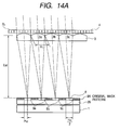
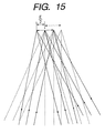
- Figs. 14A, 14B, and 15 are views for explaining this function.
- Figs. 14A and 14B are horizontal sectional views in which this embodiment is illustrated at a ratio close to the actual design values, as in Fig. 11.
- a pair of an aperture portion and a shielding portion are formed by four pixels of the optical modulator 20.
- Fig. 15 shows a state wherein light beams to which directivity is given by the vertical lenticular lens 3 are focused on the observation plane.
- the four pixels 9a of the optical modulator 20 correspond to the vertical cylindrical lens 3a of the vertical lenticular lens 3
- the four pixels 9b and 9c of the optical modulator 20 correspond to the cylindrical lenses 3b and 3c, respectively.
- Fig. 14A shows the initial observation state.
- Fig. 14B all the aperture portions of the mask pattern 9 on the optical modulator 20 are moved to the left in the horizontal direction by the width P h2 of one pixel from the state shown in Fig. 14A.
- the region illuminated with light beams transmitted through the left and right stripe pixels on the observation plane moves in the horizontal direction as a whole by 1/2 the distance E between the eyes, i.e., E/2.
- light beams from the aperture portions when the mask pattern on the optical modulator 20 is set in the initial state shown in Fig. 14A are indicated by solid lines
- light beams from the aperture portions when the mask pattern is set in the state shown in Fig. 14B are indicated by broken lines.
- the converted distance L h2 between the vertical lenticular lens 3 and the optical modulator 20 may be set at a larger value.
- the observation region can be finely moved in accordance with the number of pixels of one aperture portion.
- the observation region can be moved in the horizontal direction using E/k as a unit of movement.
- the horizontal pixel size P h1 of the display device 4 and the horizontal pixel size P h2 of the optical modulator 20 are not directly related to each other.
- the horizontal pixel size P h2 of the optical modulator 20 can be set to be equal to or larger than the horizontal pixel size P h1 of the display device 4. Therefore, the observation region can be smoothly moved in the left or right direction using a smaller unit than the distance between the eye without using any specially precise liquid crystal element as the optical modulator 20.
- Table 1 shows an actual numerical example.
- Fig. 11 is a plan view in which the structure near the optical modulator 20 and the vertical lenticular lens 3 is illustrated almost at the actual ratio in this numerical example, and corresponds to Figs. 10, 14A, and 14B.
- the pitch H L of the vertical cylindrical lens and the width H m of a pair of an aperture portion and a shielding portion formed on the optical modulator 20 in the horizontal direction hardly change.
- the horizontal stripe image displayed on the display device 4 may be combined by alternately arranging the right stripe pixels and the left stripe pixels in units of scanning lines, or stripe pixels corresponding to the width of a plurality of scanning lines may be combined.
- a self-emission type display element such as a CRT or a fluorescent indicator tube may be used as a light source means.
- the same light emission pattern as the mask pattern can be formed using light-emitting portions and non-emitting portions, and directivity can be given to the patterned exit light by the vertical lenticular lens 3.
- the horizontal pixel size P h2 of the self-emission type display element can be selected independently of the horizontal pixel size P h1 of the display device 4.
- the observation region can be moved in the horizontal direction as in the fifth embodiment.
- the observation region can be smoothly moved in the left or right direction using a smaller unit than the distance between the eyes even when the horizontal pixel size P h2 of the self-emission type display element is set to be large.
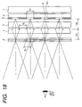
- Fig. 16 is a schematic perspective view of a stereoscopic image display apparatus according to the sixth embodiment of the present invention.
- the sixth embodiment is different from the second embodiment only in that the mask 2 of the second embodiment is changed to an optical modulator, and a mask pattern is formed on the display surface of the optical modulator.
- the remaining arrangements are the same as those of the second embodiment.
- a horizontal lenticular lens (horizontal cylindrical lens array) 7 is arranged between a vertical lenticular lens 3 and a display device 4 of the fifth embodiment.
- the horizontal lenticular lens 7 is formed by arranging, in the vertical direction, a number of cylindrical lenses each having a generatrix in the horizontal direction.
- the function associated with the horizontal direction is the same as in the fifth embodiment because the horizontal lenticular lens 7 has no optical power in the horizontal direction.
- the same stripe image as in the fifth embodiment is displayed on the display device 4.
- Light beams from a backlight source 1 are transmitted through aperture portions 8 of the mask pattern formed on an optical modulator 20 and illuminate the display device 4 through the vertical lenticular lens 3, so that left and right parallax images are separately observed with the eyes of the observer.
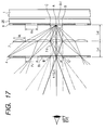
- Fig. 17 is a sectional view for explaining the function of the vertical section of the sixth embodiment. The observation region in the vertical direction will be described with reference to Fig. 17.
- the vertical lenticular lens 3 having no optical function in this section and the substrate of the display device 4 which is not directly associated with the optical function are omitted.
- the horizontal lenticular lens 7 is also schematically illustrated.
- the aperture portions of a mask pattern 9 on the optical modulator 20 are arranged in a checkerboard pattern, as shown in Fig. 16 and correspond, in the vertical direction, to the left and right stripe pixels of a horizontal stripe image displayed on the display device 4.
- the aperture pattern of the aperture portions 8 shown in Fig. 17 is to illuminate stripe pixels for one eye of the observer.
- stripe pixels (L i ) for the left eye of the observer are illuminated.
- the solid portions of the mask pattern 9 are shielding portions for shielding light beams.
- the left stripe pixels (L i ) corresponding to the left eye are represented by blank portions, and right stripe pixels (R i ) corresponding to the right eye are represented by hatched portions.
- Fig. 18 is a sectional view of this embodiment taken along the vertical direction. In Fig. 18, members omitted in Fig. 17 are illustrated.
- V m the vertical width of the aperture portion 8 of the mask pattern 9
- V L the pitch of each horizontal cylindrical lens of the horizontal lenticular lens 7, V L
- the optical function in the vertical direction need only satisfy equations (3) to (5).
- the converted distance L V2 between the optical modulator 20 and the horizontal lenticular lens 7 can be arbitrarily increased.
- the vertical lenticular lens 3 can be arranged/set independently of the characteristics of the horizontal lenticular lens 7 as far as the vertical lenticular lens 3 does not physically interfere with the remaining members.
- a converted distance L h2 between the optical modulator 20 and the vertical lenticular lens 3 can be arbitrarily increased.
- the observation region can be moved in the left or right direction using a smaller unit than a distance E between the eyes as far as the converted distance L h2 between the optical modulator 20 and the vertical lenticular lens 3 is set at a larger value according to the horizontal pixel size, as in the fifth embodiment.
- the display device 4 for displaying an image and the optical modulator 20 for forming a mask pattern can be constituted by identical LCDs.
- E represents the interval between a region illuminated with light beams having image information for the right eye and a region illuminated with light beams having image information for the left eye.
- E is larger than the average distance between the eyes of observers, i.e., 65 mm, no problem is posed in observing a stereoscopic image.
- a pair of an aperture portion and a shielding portion formed on the mask pattern 9 in the horizontal direction can be changed using, as a unit, the horizontal pixel size P h2 of the optical modulator 20.
- each of the pair of an aperture portion and a shielding portion formed on the mask pattern 9 in the horizontal direction is constituted by 20 pixels.
- H m is 3.9 mm, so that the observation distance L h1 can be changed to 1,959 mm in accordance with equation (9).
- n aperture portions and n shielding portions are used as one unit, and the sizes of some aperture portions and shielding portions in this unit are changed. Consequently, the pitch size can be effectively more finely changed.
- Fig. 19 is an explanatory view of combined apertures.
- 25 aperture portions and 25 shielding portions are set as one unit.
- Each of one aperture portion and one shielding portion in this unit is constituted by 19 pixels.
- Each of the remaining aperture portions and shielding portions is constituted by 20 pixels.
- the observation distance L h1 can be changed to 697 mm. This method will be called a combined pitch method hereinafter.
- Table 2 shows an example of actual design values according to the arrangement of this embodiment.
- the horizontal pixel size of the optical modulator 20 is set at 0.1 mm, one aperture portion or one shielding portion is formed by 20 pixels, i.e., the reference size is set at 2 mm, thereby moving the observation region in units of E/20.
- a total of 50 aperture portions and shielding portions are used as one unit, and the observation position is changed in the front-and-rear direction using the combined pitch method.
- the stereoscopic image region can be moved in the left-and-right direction and in the front-and-rear direction to follow the movement of the observer.
- Fig. 20 is a schematic perspective view of a stereoscopic image display apparatus according to the seventh embodiment of the present invention.
- a position detection means for detecting the position of the observer is set in the sixth embodiment, thereby causing the observation region to follow the movement of the observer.
- the stereoscopic image display unit is the same as that of the sixth embodiment.
- a position sensor 51 detects the position of an observer 54.
- Many methods of detecting the position of the observer are conventionally proposed. In this embodiment, various methods can be used to detect the horizontal position of the observer. For example, the image of the observer is picked up with a TV camera, and the central position of the face of the observer is obtained by image processing. To detect the distance of the observer in the front-and-rear direction, a known so-called auto-focusing method of a camera or the like may be used.
- a control unit 53 forms a mask pattern 9 on an optical modulator 20 on the basis of the position information of the observer.
- the stereoscopic image region following function of this embodiment will be described.
- the position sensor 51 detects the position of the observer in the left-and-right direction and in the front-and-rear direction. In this embodiment, control is performed in the following manner.
- the horizontal size of the jth aperture portion and the jth shielding portion in one unit is set to k j times the pixel size P h2 to form aperture portions and shielding portions.
- a checkerboard mask pattern corresponding to the distance L 0 is displayed.
- a backlight source 1 and the optical modulator 20 are used to form a patterned light source. Even when a self-emission type display element such as a CRT is used to form a patterned light source, the stereoscopic image display apparatus of this embodiment can be constituted.
- Fig. 21 is a schematic perspective view of a stereoscopic image display apparatus according to the eighth embodiment of the present invention.
- the arrangement order of two lenticular lenses is reversed to that in the seventh embodiment.
- the specifications of members are set such that equations (1) to (5) described above hold.
- the vertical optical function and the horizontal optical function are independent, as in the sixth and seventh embodiments.
- the converted distance L h2 between the optical modulator 20 and the vertical lenticular lens 3 since the converted distance L h2 between the optical modulator 20 and the vertical lenticular lens 3 is increased, the converted distance L V2 between the horizontal lenticular lens 7 and the optical modulator 20 and the converted distance L V1 between the horizontal lenticular lens 7 and the display device 4 must be set to be larger than the converted distance L h2 .
- the converted distance between the optical modulator 20 and the display device 4 is larger than twice the converted distance L h2 , so the apparatus tends to be thick.
- a vertical lenticular lens 3 is separated from an optical modulator 20 by a distance larger than that between a horizontal lenticular lens 7 and the optical modulator 20. Therefore, the converted distance between a display device 4 and the optical modulator 20 can be made almost equal to a converted distance L h2 between the optical modulator 20 and the vertical lenticular lens 3, so that the thickness of the entire apparatus can be reduced.
- the same effect as described above can be obtained independently of the arrangement order of the two lenticular lenses as far as the apparatus is constituted to satisfy conditions (1) to (5). This is because the vertical optical function and the horizontal optical function are independent, as described above.
- the observation region can be moved in the left-and-right direction and in the front-and-rear direction by the same method as that of the seventh embodiment.
- the observation region can be caused to follow the movement of the observer.
- Table 3 shows an example of actual design values according to the arrangement of this embodiment.
- This invention is to provide a stereoscopic image display apparatus for causing an observer to observe a stereoscopic image, including a light source for illuminating, with a surface illuminant, a mask substrate on which a mask pattern including aperture portions and shielding portions arranged in a checkerboard pattern is formed, a vertical cylindrical lens array constituted by vertical cylindrical lenses each having a generatrix in a vertical direction, and a transmission type display device for displaying an image on scanning lines, wherein right stripe pixels and left stripe pixels obtained by dividing a parallax image for a right eye and a parallax image for a left eye into a number of horizontal stripe pixels are alternately arranged in a predetermined order to form one image, thereby displaying a horizontal stripe image on a display surface of the display device, light beams emitted from the light source, to which directivity is given by the vertical cylindrical lens array, irradiate the horizontal stripe image, the light beams are separately condensed on at least two
Landscapes
- Engineering & Computer Science (AREA)
- Multimedia (AREA)
- Signal Processing (AREA)
- Physics & Mathematics (AREA)
- General Physics & Mathematics (AREA)
- Optics & Photonics (AREA)
- Testing, Inspecting, Measuring Of Stereoscopic Televisions And Televisions (AREA)
- Stereoscopic And Panoramic Photography (AREA)
- Liquid Crystal (AREA)
Applications Claiming Priority (2)
| Application Number | Priority Date | Filing Date | Title |
|---|---|---|---|
| JP250943/96 | 1996-09-02 | ||
| JP25094396A JP3703225B2 (ja) | 1996-09-02 | 1996-09-02 | 立体画像表示方法及びそれを用いた立体画像表示装置 |
Publications (2)
| Publication Number | Publication Date |
|---|---|
| EP0827350A2 true EP0827350A2 (fr) | 1998-03-04 |
| EP0827350A3 EP0827350A3 (fr) | 1999-04-21 |
Family
ID=17215322
Family Applications (1)
| Application Number | Title | Priority Date | Filing Date |
|---|---|---|---|
| EP97115121A Withdrawn EP0827350A3 (fr) | 1996-09-02 | 1997-09-01 | Dispositif d'affichage d'images stéréoscopiques |
Country Status (3)
| Country | Link |
|---|---|
| US (1) | US6160527A (fr) |
| EP (1) | EP0827350A3 (fr) |
| JP (1) | JP3703225B2 (fr) |
Cited By (12)
| Publication number | Priority date | Publication date | Assignee | Title |
|---|---|---|---|---|
| EP0859525A2 (fr) * | 1997-02-18 | 1998-08-19 | Canon Kabushiki Kaisha | Dispositif d'affichage d'images stéreoscopiques utilisant un motif de masque spécifique |
| EP0969418A2 (fr) * | 1998-06-30 | 2000-01-05 | Mixed Reality Systems Laboratory Inc. | Appareil de traítement d'images pour afficher des images tridimensionelles |
| EP0977445A2 (fr) * | 1998-07-27 | 2000-02-02 | Mixed Reality Systems Laboratory Inc. | Dispositif d'affichage d'images stéréoscopiques |
| US6462871B1 (en) | 1997-02-18 | 2002-10-08 | Canon Kabushiki Kaisha | Stereoscopic image display apparatus using specific mask pattern |
| WO2003013153A1 (fr) * | 2001-07-27 | 2003-02-13 | Koninklijke Philips Electronics N.V. | Dispositif d'affichage d'image autostereoscopique pourvu d'un systeme de reperage d'utilisateur |
| GB2387664A (en) * | 2002-04-17 | 2003-10-22 | Philip Anthony Surman | Autostereoscopic display system with horizontal apertures |
| EP1658731B1 (fr) * | 2003-08-26 | 2008-02-27 | SeeReal Technologies GmbH | Ecran multi-utilisateurs autostereoscopique |
| CN100459719C (zh) * | 2003-09-04 | 2009-02-04 | 株式会社东芝 | 三维影像显示装置和方法及三维显示用影像数据生成方法 |
| EP2180716A1 (fr) * | 2008-10-21 | 2010-04-28 | Electronics and Telecommunications Research Institute | Affichage autostéréoscopique avec poursuite d'observateur |
| KR101257827B1 (ko) | 2012-09-20 | 2013-04-29 | (주)프로비전 | 라인형 레이저 빔 형성 장치 및 이를 이용한 터치 패널 제조 방법 |
| WO2016180048A1 (fr) * | 2015-05-13 | 2016-11-17 | 京东方科技集团股份有限公司 | Dispositif d'affichage et son procédé de commande |
| WO2018049840A1 (fr) * | 2016-09-19 | 2018-03-22 | 京东方科技集团股份有限公司 | Dispositif d'affichage et procédé de commande de la luminosité du dispositif d'affichage |
Families Citing this family (42)
| Publication number | Priority date | Publication date | Assignee | Title |
|---|---|---|---|---|
| JPH10232626A (ja) * | 1997-02-20 | 1998-09-02 | Canon Inc | 立体画像表示装置 |
| US6798390B1 (en) * | 1997-08-29 | 2004-09-28 | Canon Kabushiki Kaisha | 3D image reconstructing apparatus and 3D object inputting apparatus |
| US6757422B1 (en) | 1998-11-12 | 2004-06-29 | Canon Kabushiki Kaisha | Viewpoint position detection apparatus and method, and stereoscopic image display system |
| GB2351866A (en) * | 1999-07-07 | 2001-01-10 | Sharp Kk | Stereoscopic display |
| US6335714B1 (en) * | 1999-07-28 | 2002-01-01 | Dynascan Technology Corp. | Display apparatus having a rotating display panel |
| JP3450801B2 (ja) * | 2000-05-31 | 2003-09-29 | キヤノン株式会社 | 瞳孔位置検出装置及び方法、視点位置検出装置及び方法、並びに立体画像表示システム |
| JP3647376B2 (ja) | 2001-01-31 | 2005-05-11 | キヤノン株式会社 | 視点位置検出装置、視点位置検出方法及び立体画像表示システム |
| JP2003337303A (ja) * | 2002-05-17 | 2003-11-28 | Canon Inc | 立体画像表示装置および立体画像表示システム |
| GB2396070A (en) | 2002-12-07 | 2004-06-09 | Sharp Kk | Multiple view display |
| AU2003293847A1 (en) * | 2002-12-13 | 2004-07-09 | Hentze Lissotschenko Patentverwaltungs Gmbh And Co. Kg | Device for recording and device for reproducing three-dimensional items of image information of an object |
| JP4200056B2 (ja) * | 2003-06-17 | 2008-12-24 | 有限会社シーフォン | 表示装置 |
| JP3955002B2 (ja) * | 2003-09-09 | 2007-08-08 | 三洋電機株式会社 | 映像表示装置 |
| US7372629B2 (en) * | 2003-11-06 | 2008-05-13 | Nec Corporation | Three-dimensional image display device, portable terminal device, display panel and fly eye lens |
| WO2005104545A2 (fr) * | 2004-04-19 | 2005-11-03 | The Trustees Of Columbia University In The City Of New York | Procedes et systemes permettant d'afficher des images tridimensionnelles |
| US7724210B2 (en) * | 2004-05-07 | 2010-05-25 | Microvision, Inc. | Scanned light display system using large numerical aperture light source, method of using same, and method of making scanning mirror assemblies |
| US20060061846A1 (en) * | 2004-09-17 | 2006-03-23 | Microvision, Inc. | Scanned light display system using array of collimating elements in conjunction with large numerical aperture light emitter array |
| CN101088298B (zh) * | 2004-12-22 | 2010-12-15 | 马斯特图像3D亚洲有限责任公司 | 视差阻挡型立体显示设备 |
| DE102005040597A1 (de) * | 2005-02-25 | 2007-02-22 | Seereal Technologies Gmbh | Verfahren und Einrichtung zum Nachführen von Sweet-Spots |
| JP4934974B2 (ja) * | 2005-03-17 | 2012-05-23 | エプソンイメージングデバイス株式会社 | 画像表示装置 |
| JP4863044B2 (ja) * | 2005-07-21 | 2012-01-25 | ソニー株式会社 | 表示装置、表示制御方法、並びにプログラム |
| EP1932053A4 (fr) * | 2005-09-16 | 2010-06-02 | Stereographics Corp | Procede et appareil destines a optimiser la vision d'un stereogramme lenticulaire |
| KR100753517B1 (ko) * | 2005-10-12 | 2007-08-31 | 엘지전자 주식회사 | 입체 영상 디스플레이 기능을 갖는 이동통신 단말기 및이를 이용한 입체 영상 디스플레이 방법 |
| US20080043487A1 (en) * | 2006-08-21 | 2008-02-21 | Sprague Randall B | Light bar structure having light conduits and scanned light display system employing same |
| CN101193322B (zh) * | 2006-11-20 | 2010-04-14 | 广达电脑股份有限公司 | 立体影像显示方法及应用该方法的显示系统 |
| JP2010032675A (ja) * | 2008-07-28 | 2010-02-12 | Sony Corp | 立体画像表示装置の製造方法および立体画像表示装置 |
| JP4582219B2 (ja) * | 2008-07-28 | 2010-11-17 | ソニー株式会社 | 立体画像表示装置およびその製造方法 |
| US20100033557A1 (en) * | 2008-07-28 | 2010-02-11 | Sony Corporation | Stereoscopic image display and method for producing the same |
| JP4525808B2 (ja) * | 2008-07-28 | 2010-08-18 | ソニー株式会社 | 立体画像表示装置およびその製造方法 |
| US8314832B2 (en) * | 2009-04-01 | 2012-11-20 | Microsoft Corporation | Systems and methods for generating stereoscopic images |
| KR101626063B1 (ko) | 2010-01-21 | 2016-06-01 | 삼성디스플레이 주식회사 | 입체 영상 표시 방법 및 이를 수행하기 위한 표시 장치 |
| JP2011186224A (ja) * | 2010-03-09 | 2011-09-22 | Sony Corp | 液晶表示装置および映像表示システム |
| US8704879B1 (en) | 2010-08-31 | 2014-04-22 | Nintendo Co., Ltd. | Eye tracking enabling 3D viewing on conventional 2D display |
| WO2012046424A1 (fr) * | 2010-10-04 | 2012-04-12 | パナソニック株式会社 | Dispositif d'affichage vidéo |
| JP6099892B2 (ja) * | 2012-07-09 | 2017-03-22 | パナソニック インテレクチュアル プロパティ コーポレーション オブ アメリカPanasonic Intellectual Property Corporation of America | 映像表示装置 |
| JP6145721B2 (ja) * | 2013-02-19 | 2017-06-14 | パナソニックIpマネジメント株式会社 | 画像表示装置 |
| CN103605211B (zh) * | 2013-11-27 | 2016-04-20 | 南京大学 | 平板化无辅助立体显示装置及方法 |
| US10001583B2 (en) * | 2015-04-06 | 2018-06-19 | Heptagon Micro Optics Pte. Ltd. | Structured light projection using a compound patterned mask |
| JP6791058B2 (ja) * | 2017-08-09 | 2020-11-25 | 株式会社デンソー | 立体表示装置 |
| US10175490B1 (en) * | 2017-12-20 | 2019-01-08 | Aperture In Motion, LLC | Light control devices and methods for regional variation of visual information and sampling |
| US10768431B2 (en) | 2017-12-20 | 2020-09-08 | Aperture In Motion, LLC | Light control devices and methods for regional variation of visual information and sampling |
| CN109521575B (zh) * | 2018-11-20 | 2023-09-22 | 成都航空职业技术学院 | 基于背光源的集成成像3d显示装置 |
| CN109298539B (zh) * | 2018-11-20 | 2023-09-19 | 成都航空职业技术学院 | 均匀光学效率的集成成像3d显示装置 |
Citations (3)
| Publication number | Priority date | Publication date | Assignee | Title |
|---|---|---|---|---|
| EP0540137A1 (fr) * | 1991-10-28 | 1993-05-05 | Nippon Hoso Kyokai | Dispositif d'affichage d'images tridimensionnelles utilisant des bandes parallaxes générées électriquement |
| EP0726482A2 (fr) * | 1995-02-09 | 1996-08-14 | Sharp Kabushiki Kaisha | Dispositif d'affichage autostéréoscopique et méthode de commande d'un tel dispositif |
| EP0788008A1 (fr) * | 1996-01-31 | 1997-08-06 | Canon Kabushiki Kaisha | Dispositif d'affichage d'images stéréoscopiques avec un champ d'observation élargi |
Family Cites Families (18)
| Publication number | Priority date | Publication date | Assignee | Title |
|---|---|---|---|---|
| ES2000293A6 (es) * | 1986-12-29 | 1988-02-01 | Dominguez Montes Juan | Instalacion y procedimiento para obtener imagenes tridimensionales en movimiento esto es tetradimimensionales tanto en color como en blanco y negro |
| JPH01296214A (ja) * | 1988-05-25 | 1989-11-29 | Canon Inc | 表示装置 |
| JP2585717B2 (ja) * | 1988-06-03 | 1997-02-26 | キヤノン株式会社 | 表示装置 |
| JPH0244995A (ja) * | 1988-08-05 | 1990-02-14 | Nippon Telegr & Teleph Corp <Ntt> | 3次元画像表示装置の光指向制御方法 |
| JP2662252B2 (ja) * | 1988-08-12 | 1997-10-08 | 日本電信電話株式会社 | 立体像表示装置 |
| US5162928A (en) * | 1988-11-02 | 1992-11-10 | Canon Kabushiki Kaisha | Head-up display apparatus |
| JP2653186B2 (ja) * | 1989-09-27 | 1997-09-10 | キヤノン株式会社 | ヘッドアップディスプレイ装置 |
| JP2705245B2 (ja) * | 1989-09-27 | 1998-01-28 | キヤノン株式会社 | ヘッドアップディスプレイ装置 |
| GB9027881D0 (en) * | 1990-12-21 | 1991-02-13 | Delta System Design Ltd | Improvements in 3d imaging systems |
| JP3072866B2 (ja) * | 1991-10-15 | 2000-08-07 | 日本電信電話株式会社 | 3次元立体画像表示装置 |
| JP3151766B2 (ja) * | 1992-07-31 | 2001-04-03 | キヤノン株式会社 | 画像表示装置 |
| JP3059590B2 (ja) * | 1992-09-30 | 2000-07-04 | 富士通株式会社 | 立体表示方法及び装置 |
| JPH06175075A (ja) * | 1992-12-08 | 1994-06-24 | Canon Inc | 画像表示装置 |
| ES2165644T3 (es) * | 1993-05-05 | 2002-03-16 | Pierre Allio | Dispositivo de video autoestereoscopico. |
| JPH0775137A (ja) * | 1993-08-31 | 1995-03-17 | Sony Corp | 立体映像用めがね |
| JPH07234459A (ja) * | 1994-02-23 | 1995-09-05 | Sanyo Electric Co Ltd | 立体映像表示装置 |
| JP2951202B2 (ja) * | 1994-02-23 | 1999-09-20 | 三洋電機株式会社 | メガネ無し立体表示装置 |
| JPH0915532A (ja) * | 1995-06-29 | 1997-01-17 | Canon Inc | 立体画像表示方法及びそれを用いた立体画像表示装置 |
-
1996
- 1996-09-02 JP JP25094396A patent/JP3703225B2/ja not_active Expired - Fee Related
-
1997
- 1997-08-29 US US08/921,362 patent/US6160527A/en not_active Expired - Fee Related
- 1997-09-01 EP EP97115121A patent/EP0827350A3/fr not_active Withdrawn
Patent Citations (3)
| Publication number | Priority date | Publication date | Assignee | Title |
|---|---|---|---|---|
| EP0540137A1 (fr) * | 1991-10-28 | 1993-05-05 | Nippon Hoso Kyokai | Dispositif d'affichage d'images tridimensionnelles utilisant des bandes parallaxes générées électriquement |
| EP0726482A2 (fr) * | 1995-02-09 | 1996-08-14 | Sharp Kabushiki Kaisha | Dispositif d'affichage autostéréoscopique et méthode de commande d'un tel dispositif |
| EP0788008A1 (fr) * | 1996-01-31 | 1997-08-06 | Canon Kabushiki Kaisha | Dispositif d'affichage d'images stéréoscopiques avec un champ d'observation élargi |
Cited By (19)
| Publication number | Priority date | Publication date | Assignee | Title |
|---|---|---|---|---|
| EP0859525A3 (fr) * | 1997-02-18 | 1999-03-24 | Canon Kabushiki Kaisha | Dispositif d'affichage d'images stéreoscopiques utilisant un motif de masque spécifique |
| US6151062A (en) * | 1997-02-18 | 2000-11-21 | Canon Kabushiki Kaisha | Stereoscopic image display apparatus using specific mask pattern |
| US6462871B1 (en) | 1997-02-18 | 2002-10-08 | Canon Kabushiki Kaisha | Stereoscopic image display apparatus using specific mask pattern |
| EP0859525A2 (fr) * | 1997-02-18 | 1998-08-19 | Canon Kabushiki Kaisha | Dispositif d'affichage d'images stéreoscopiques utilisant un motif de masque spécifique |
| US6760020B1 (en) | 1998-06-30 | 2004-07-06 | Canon Kabushiki Kaisha | Image processing apparatus for displaying three-dimensional image |
| EP0969418A2 (fr) * | 1998-06-30 | 2000-01-05 | Mixed Reality Systems Laboratory Inc. | Appareil de traítement d'images pour afficher des images tridimensionelles |
| EP0969418A3 (fr) * | 1998-06-30 | 2001-05-02 | Mixed Reality Systems Laboratory Inc. | Appareil de traítement d'images pour afficher des images tridimensionelles |
| EP0977445A2 (fr) * | 1998-07-27 | 2000-02-02 | Mixed Reality Systems Laboratory Inc. | Dispositif d'affichage d'images stéréoscopiques |
| EP0977445A3 (fr) * | 1998-07-27 | 2003-01-22 | Canon Kabushiki Kaisha | Dispositif d'affichage d'images stéréoscopiques |
| WO2003013153A1 (fr) * | 2001-07-27 | 2003-02-13 | Koninklijke Philips Electronics N.V. | Dispositif d'affichage d'image autostereoscopique pourvu d'un systeme de reperage d'utilisateur |
| GB2387664A (en) * | 2002-04-17 | 2003-10-22 | Philip Anthony Surman | Autostereoscopic display system with horizontal apertures |
| GB2387664B (en) * | 2002-04-17 | 2005-08-24 | Philip Anthony Surman | Autostereoscopic display |
| EP1658731B1 (fr) * | 2003-08-26 | 2008-02-27 | SeeReal Technologies GmbH | Ecran multi-utilisateurs autostereoscopique |
| CN100459719C (zh) * | 2003-09-04 | 2009-02-04 | 株式会社东芝 | 三维影像显示装置和方法及三维显示用影像数据生成方法 |
| EP2180716A1 (fr) * | 2008-10-21 | 2010-04-28 | Electronics and Telecommunications Research Institute | Affichage autostéréoscopique avec poursuite d'observateur |
| KR101257827B1 (ko) | 2012-09-20 | 2013-04-29 | (주)프로비전 | 라인형 레이저 빔 형성 장치 및 이를 이용한 터치 패널 제조 방법 |
| WO2016180048A1 (fr) * | 2015-05-13 | 2016-11-17 | 京东方科技集团股份有限公司 | Dispositif d'affichage et son procédé de commande |
| US9875705B2 (en) | 2015-05-13 | 2018-01-23 | Boe Technology Group Co., Ltd. | Display apparatus and method of driving the same |
| WO2018049840A1 (fr) * | 2016-09-19 | 2018-03-22 | 京东方科技集团股份有限公司 | Dispositif d'affichage et procédé de commande de la luminosité du dispositif d'affichage |
Also Published As
| Publication number | Publication date |
|---|---|
| EP0827350A3 (fr) | 1999-04-21 |
| US6160527A (en) | 2000-12-12 |
| JP3703225B2 (ja) | 2005-10-05 |
| JPH1078563A (ja) | 1998-03-24 |
Similar Documents
| Publication | Publication Date | Title |
|---|---|---|
| US6160527A (en) | Stereoscopic image display apparatus | |
| EP0788008B1 (fr) | Dispositif d'affichage d'images stéréoscopiques avec un champ d'observation élargi | |
| US5991074A (en) | Stereoscopic image display apparatus | |
| US6061179A (en) | Stereoscopic image display apparatus with two-/three-dimensional image display switching function | |
| US6462871B1 (en) | Stereoscopic image display apparatus using specific mask pattern | |
| US6710920B1 (en) | Stereoscopic display | |
| US6151062A (en) | Stereoscopic image display apparatus using specific mask pattern | |
| JP2891177B2 (ja) | 立体表示装置 | |
| US8125513B2 (en) | Stereoscopic display device and display method | |
| US6337721B1 (en) | Stereoscopic display | |
| KR100658545B1 (ko) | 입체 화상 재생 장치 | |
| US20030067460A1 (en) | Three-dimensional image display apparatus | |
| EP1185113A2 (fr) | Méthode et dispositif d'affichage d'images stéréoscopiques | |
| JPH11285030A (ja) | 立体画像表示方法及び立体画像表示装置 | |
| US20060227208A1 (en) | Stereoscopic image display apparatus and stereoscopic image display method | |
| JPH10221644A (ja) | 立体画像表示装置 | |
| JP3728013B2 (ja) | 立体画像表示装置 | |
| EP1083756A2 (fr) | Dispositif d'affichage d'images stéréoscopiques | |
| JPH085957A (ja) | メガネ無し立体表示装置 | |
| JP2000206456A (ja) | 立体画像表示装置 | |
| JPH11285031A (ja) | 立体画像表示装置 | |
| JP2002228980A (ja) | 立体画像表示装置 | |
| JP3634486B2 (ja) | 立体映像の表示方法 | |
| JP3056581B2 (ja) | 投写型立体表示装置 | |
| JP3108351B2 (ja) | 投写型立体映像表示装置 |
Legal Events
| Date | Code | Title | Description |
|---|---|---|---|
| PUAI | Public reference made under article 153(3) epc to a published international application that has entered the european phase |
Free format text: ORIGINAL CODE: 0009012 |
|
| AK | Designated contracting states |
Kind code of ref document: A2 Designated state(s): DE FR GB IT NL |
|
| PUAL | Search report despatched |
Free format text: ORIGINAL CODE: 0009013 |
|
| AK | Designated contracting states |
Kind code of ref document: A3 Designated state(s): AT BE CH DE DK ES FI FR GB GR IE IT LI LU MC NL PT SE |
|
| 17P | Request for examination filed |
Effective date: 19991005 |
|
| AKX | Designation fees paid |
Free format text: DE FR GB IT NL |
|
| 17Q | First examination report despatched |
Effective date: 20030530 |
|
| STAA | Information on the status of an ep patent application or granted ep patent |
Free format text: STATUS: THE APPLICATION HAS BEEN WITHDRAWN |
|
| 18W | Application withdrawn |
Effective date: 20080325 |