EP0826941A2 - Rohrblock-Wärmeübertrager - Google Patents
Rohrblock-Wärmeübertrager Download PDFInfo
- Publication number
- EP0826941A2 EP0826941A2 EP97113381A EP97113381A EP0826941A2 EP 0826941 A2 EP0826941 A2 EP 0826941A2 EP 97113381 A EP97113381 A EP 97113381A EP 97113381 A EP97113381 A EP 97113381A EP 0826941 A2 EP0826941 A2 EP 0826941A2
- Authority
- EP
- European Patent Office
- Prior art keywords
- spacer
- pipe block
- pipe
- heat exchanger
- spacers
- Prior art date
- Legal status (The legal status is an assumption and is not a legal conclusion. Google has not performed a legal analysis and makes no representation as to the accuracy of the status listed.)
- Granted
Links
- 125000006850 spacer group Chemical group 0.000 claims abstract description 58
- 239000012530 fluid Substances 0.000 claims abstract description 11
- 238000000926 separation method Methods 0.000 claims description 21
- 238000005192 partition Methods 0.000 abstract 1
- 238000000638 solvent extraction Methods 0.000 abstract 1
- 238000009826 distribution Methods 0.000 description 6
- 238000004519 manufacturing process Methods 0.000 description 5
- 238000010276 construction Methods 0.000 description 4
- 239000003921 oil Substances 0.000 description 4
- 238000005476 soldering Methods 0.000 description 4
- 238000001816 cooling Methods 0.000 description 3
- 239000010705 motor oil Substances 0.000 description 3
- 239000012208 gear oil Substances 0.000 description 2
- 238000007789 sealing Methods 0.000 description 2
- 238000012546 transfer Methods 0.000 description 2
- FIKFLLIUPUVONI-UHFFFAOYSA-N 8-(2-phenylethyl)-1-oxa-3,8-diazaspiro[4.5]decan-2-one;hydrochloride Chemical compound Cl.O1C(=O)NCC11CCN(CCC=2C=CC=CC=2)CC1 FIKFLLIUPUVONI-UHFFFAOYSA-N 0.000 description 1
- 238000004026 adhesive bonding Methods 0.000 description 1
- 230000005540 biological transmission Effects 0.000 description 1
- 230000015572 biosynthetic process Effects 0.000 description 1
- 210000001520 comb Anatomy 0.000 description 1
- 230000000052 comparative effect Effects 0.000 description 1
- 238000011161 development Methods 0.000 description 1
- 238000005516 engineering process Methods 0.000 description 1
- 238000003780 insertion Methods 0.000 description 1
- 230000037431 insertion Effects 0.000 description 1
- 238000009434 installation Methods 0.000 description 1
- 239000007788 liquid Substances 0.000 description 1
- 238000000034 method Methods 0.000 description 1
- XLYOFNOQVPJJNP-UHFFFAOYSA-N water Substances O XLYOFNOQVPJJNP-UHFFFAOYSA-N 0.000 description 1
Images
Classifications
-
- F—MECHANICAL ENGINEERING; LIGHTING; HEATING; WEAPONS; BLASTING
- F28—HEAT EXCHANGE IN GENERAL
- F28D—HEAT-EXCHANGE APPARATUS, NOT PROVIDED FOR IN ANOTHER SUBCLASS, IN WHICH THE HEAT-EXCHANGE MEDIA DO NOT COME INTO DIRECT CONTACT
- F28D1/00—Heat-exchange apparatus having stationary conduit assemblies for one heat-exchange medium only, the media being in contact with different sides of the conduit wall, in which the other heat-exchange medium is a large body of fluid, e.g. domestic or motor car radiators
- F28D1/02—Heat-exchange apparatus having stationary conduit assemblies for one heat-exchange medium only, the media being in contact with different sides of the conduit wall, in which the other heat-exchange medium is a large body of fluid, e.g. domestic or motor car radiators with heat-exchange conduits immersed in the body of fluid
- F28D1/04—Heat-exchange apparatus having stationary conduit assemblies for one heat-exchange medium only, the media being in contact with different sides of the conduit wall, in which the other heat-exchange medium is a large body of fluid, e.g. domestic or motor car radiators with heat-exchange conduits immersed in the body of fluid with tubular conduits
- F28D1/053—Heat-exchange apparatus having stationary conduit assemblies for one heat-exchange medium only, the media being in contact with different sides of the conduit wall, in which the other heat-exchange medium is a large body of fluid, e.g. domestic or motor car radiators with heat-exchange conduits immersed in the body of fluid with tubular conduits the conduits being straight
- F28D1/0535—Heat-exchange apparatus having stationary conduit assemblies for one heat-exchange medium only, the media being in contact with different sides of the conduit wall, in which the other heat-exchange medium is a large body of fluid, e.g. domestic or motor car radiators with heat-exchange conduits immersed in the body of fluid with tubular conduits the conduits being straight the conduits having a non-circular cross-section
- F28D1/05366—Assemblies of conduits connected to common headers, e.g. core type radiators
-
- F—MECHANICAL ENGINEERING; LIGHTING; HEATING; WEAPONS; BLASTING
- F28—HEAT EXCHANGE IN GENERAL
- F28D—HEAT-EXCHANGE APPARATUS, NOT PROVIDED FOR IN ANOTHER SUBCLASS, IN WHICH THE HEAT-EXCHANGE MEDIA DO NOT COME INTO DIRECT CONTACT
- F28D1/00—Heat-exchange apparatus having stationary conduit assemblies for one heat-exchange medium only, the media being in contact with different sides of the conduit wall, in which the other heat-exchange medium is a large body of fluid, e.g. domestic or motor car radiators
- F28D1/02—Heat-exchange apparatus having stationary conduit assemblies for one heat-exchange medium only, the media being in contact with different sides of the conduit wall, in which the other heat-exchange medium is a large body of fluid, e.g. domestic or motor car radiators with heat-exchange conduits immersed in the body of fluid
- F28D1/03—Heat-exchange apparatus having stationary conduit assemblies for one heat-exchange medium only, the media being in contact with different sides of the conduit wall, in which the other heat-exchange medium is a large body of fluid, e.g. domestic or motor car radiators with heat-exchange conduits immersed in the body of fluid with plate-like or laminated conduits
- F28D1/0308—Heat-exchange apparatus having stationary conduit assemblies for one heat-exchange medium only, the media being in contact with different sides of the conduit wall, in which the other heat-exchange medium is a large body of fluid, e.g. domestic or motor car radiators with heat-exchange conduits immersed in the body of fluid with plate-like or laminated conduits the conduits being formed by paired plates touching each other
- F28D1/0325—Heat-exchange apparatus having stationary conduit assemblies for one heat-exchange medium only, the media being in contact with different sides of the conduit wall, in which the other heat-exchange medium is a large body of fluid, e.g. domestic or motor car radiators with heat-exchange conduits immersed in the body of fluid with plate-like or laminated conduits the conduits being formed by paired plates touching each other the plates having lateral openings therein for circulation of the heat-exchange medium from one conduit to another
-
- F—MECHANICAL ENGINEERING; LIGHTING; HEATING; WEAPONS; BLASTING
- F28—HEAT EXCHANGE IN GENERAL
- F28F—DETAILS OF HEAT-EXCHANGE AND HEAT-TRANSFER APPARATUS, OF GENERAL APPLICATION
- F28F9/00—Casings; Header boxes; Auxiliary supports for elements; Auxiliary members within casings
- F28F9/001—Casings in the form of plate-like arrangements; Frames enclosing a heat exchange core
- F28F9/002—Casings in the form of plate-like arrangements; Frames enclosing a heat exchange core with fastening means for other structures
-
- F—MECHANICAL ENGINEERING; LIGHTING; HEATING; WEAPONS; BLASTING
- F28—HEAT EXCHANGE IN GENERAL
- F28F—DETAILS OF HEAT-EXCHANGE AND HEAT-TRANSFER APPARATUS, OF GENERAL APPLICATION
- F28F9/00—Casings; Header boxes; Auxiliary supports for elements; Auxiliary members within casings
- F28F9/02—Header boxes; End plates
- F28F9/0202—Header boxes having their inner space divided by partitions
- F28F9/0204—Header boxes having their inner space divided by partitions for elongated header box, e.g. with transversal and longitudinal partitions
- F28F9/0209—Header boxes having their inner space divided by partitions for elongated header box, e.g. with transversal and longitudinal partitions having only transversal partitions
- F28F9/0212—Header boxes having their inner space divided by partitions for elongated header box, e.g. with transversal and longitudinal partitions having only transversal partitions the partitions being separate elements attached to header boxes
-
- F—MECHANICAL ENGINEERING; LIGHTING; HEATING; WEAPONS; BLASTING
- F28—HEAT EXCHANGE IN GENERAL
- F28F—DETAILS OF HEAT-EXCHANGE AND HEAT-TRANSFER APPARATUS, OF GENERAL APPLICATION
- F28F9/00—Casings; Header boxes; Auxiliary supports for elements; Auxiliary members within casings
- F28F9/02—Header boxes; End plates
- F28F9/0219—Arrangements for sealing end plates into casing or header box; Header box sub-elements
- F28F9/0221—Header boxes or end plates formed by stacked elements
-
- F—MECHANICAL ENGINEERING; LIGHTING; HEATING; WEAPONS; BLASTING
- F28—HEAT EXCHANGE IN GENERAL
- F28D—HEAT-EXCHANGE APPARATUS, NOT PROVIDED FOR IN ANOTHER SUBCLASS, IN WHICH THE HEAT-EXCHANGE MEDIA DO NOT COME INTO DIRECT CONTACT
- F28D21/00—Heat-exchange apparatus not covered by any of the groups F28D1/00 - F28D20/00
- F28D2021/0019—Other heat exchangers for particular applications; Heat exchange systems not otherwise provided for
- F28D2021/008—Other heat exchangers for particular applications; Heat exchange systems not otherwise provided for for vehicles
- F28D2021/0089—Oil coolers
-
- F—MECHANICAL ENGINEERING; LIGHTING; HEATING; WEAPONS; BLASTING
- F28—HEAT EXCHANGE IN GENERAL
- F28D—HEAT-EXCHANGE APPARATUS, NOT PROVIDED FOR IN ANOTHER SUBCLASS, IN WHICH THE HEAT-EXCHANGE MEDIA DO NOT COME INTO DIRECT CONTACT
- F28D21/00—Heat-exchange apparatus not covered by any of the groups F28D1/00 - F28D20/00
- F28D2021/0019—Other heat exchangers for particular applications; Heat exchange systems not otherwise provided for
- F28D2021/008—Other heat exchangers for particular applications; Heat exchange systems not otherwise provided for for vehicles
- F28D2021/0091—Radiators
- F28D2021/0094—Radiators for recooling the engine coolant
-
- F—MECHANICAL ENGINEERING; LIGHTING; HEATING; WEAPONS; BLASTING
- F28—HEAT EXCHANGE IN GENERAL
- F28F—DETAILS OF HEAT-EXCHANGE AND HEAT-TRANSFER APPARATUS, OF GENERAL APPLICATION
- F28F2280/00—Mounting arrangements; Arrangements for facilitating assembling or disassembling of heat exchanger parts
- F28F2280/04—Means for preventing wrong assembling of parts
-
- Y—GENERAL TAGGING OF NEW TECHNOLOGICAL DEVELOPMENTS; GENERAL TAGGING OF CROSS-SECTIONAL TECHNOLOGIES SPANNING OVER SEVERAL SECTIONS OF THE IPC; TECHNICAL SUBJECTS COVERED BY FORMER USPC CROSS-REFERENCE ART COLLECTIONS [XRACs] AND DIGESTS
- Y10—TECHNICAL SUBJECTS COVERED BY FORMER USPC
- Y10S—TECHNICAL SUBJECTS COVERED BY FORMER USPC CROSS-REFERENCE ART COLLECTIONS [XRACs] AND DIGESTS
- Y10S165/00—Heat exchange
- Y10S165/916—Oil cooler
Definitions
- the invention relates to a tube block heat exchanger according to the preamble of claim 1.
- Such heat exchanger are for example in flat tube construction as Oil / air cooler or as water / air cooler in motor vehicles used.
- the one to be cooled flows Liquid from a connection channel functioning as a distribution channel on one side of the pipe block through the pipes to a connection channel functioning as a collecting channel the other tube block side and is from between the tubes blown air cooled.
- To improve the Heat transfer is usually a rib structure in the spaces inserted between the tubes.
- a tube block heat exchanger of this type is for example in published patent application EP 0 479 012 A1.
- There are the flat tubes by means of an intermediate floor or Support comb is kept at a distance on each side of the pipe block.
- the pipes enter through through openings through the intermediate floors or the support combs and open open at the end in laterally adjoining, box-shaped, as Connection channels serving distribution or collecting channels.
- the invention is a technical problem of providing a tube block heat exchanger of the aforementioned Type based, which is comparatively easy to manufacture and has at least two separate fluid circuits.
- the invention solves this problem by providing it a tube block heat exchanger with the features of the claim 1.
- This heat exchanger has a comparative easy to manufacture structure from individual, spaced tubes lying side by side and sealed at the ends as well as spacer elements between two neighboring Pipe end areas are introduced to the desired spaces to form between the tubes.
- the necessary Connection channels on the pipe block cross sides are through respective Cross openings formed in the end areas of the pipes and in the spacers with the exception of the separation spacers are provided.
- the height in the tube block is opposite on each side of the tube block in a technically simple manner two or more separate connection channels are formed.
- Of the Pipe block is thereby in successive pipe block sections divided, which flows through by several fluids separately can be.
- Such a heat exchanger can for example for the simultaneous cooling of Engine oil on the one hand and gear oil on the other hand by means of air be used in a motor vehicle. It is only to fix a single radiator block in the vehicle, which without can also be designed as a large area cooler.
- U-shaped Spacer shoes are provided, each of which has an associated one Grips pipe end area, with adjacent spacers placed in contact and firmly together are connected.
- the spacers which keep adjacent pipes at a distance from each other connected halves of two successive spacer shoes educated.
- the separation spacer elements are thereby realizes that associated, opposite one another at the same height Spacer halves not with a continuous Cross opening are provided.
- This heat exchanger construction allows the insertion of the separation spacer elements very flexibly at any desired height of the Pipe block, so that the pipe block in its overall dimensions, especially the number of tubes used, as also with regard to its division into fluid-separated ones Pipe block sections in the production without major Additional effort optimal for the respective application can be coordinated.
- heat exchanger are the separation spacers on their exposed ones Outside areas designed differently than the other spacer elements, and in such a way that this is from a corresponding Sensor technology can be detected. This way is finished Pipe block heat exchanger can be quickly determined where there are separation spacers are located.
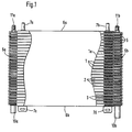
- the tube block heat exchanger shown in Fig. 1 includes a pipe block of several, in a row in the pipe transverse direction spaced apart flat tubes (1).
- corrugated ribs (3) which in Fig. 1 only partially shown for clarity are.
- the corrugated fins (3) serve for improved heat transfer between air that is perpendicular to the plane of the drawing Fig. 1 is blown through the gaps (2), and the fluid flowing in the flat tubes (1).
- each is Flat tube (1) sealed at both ends, e.g. by attaching a flat fold and possibly additional Sealing soldering.
- Each is at both end ranges Flat tube (1), each with a continuous transverse opening (4a, 4b) Mistake.
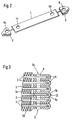
- the tube end areas are each U-shaped Grasp the spacer shoe (5).
- To manufacture the heat exchanger are, as indicated by the arrows in Fig. 2, initially the two spacer shoes (5) on each flat tube (1) attached and then the spacer shoe flat tube units thus obtained put together in a row so that neighboring Touch spacer shoes (5).
- each spacer shoe (5) firmly with the encompassed pipe end area is connected, so that a rigid pipe block structure results. This is through along one end plate element (6a, 6b) each, at which Fastening elements (7a, 7b, 7c, 7d) are provided, with which the pipe block heat exchanger at the desired installation location can be attached.
- connection channels along the two sides of the pipe are the distance shoes (5) with the exception of two special ones Separation spacers (5a, 5b) on each of their two Halves each have a transverse opening (8).
- the spacer shoe cross openings (8) are aligned when the tube block assembly is completed one below the other on the respective transverse pipe side and with the associated pipe transverse openings (4a, 4b), whereby a respective connection channel serving as a distribution or collection channel is formed.
- the separation spacer shoes (5a, 5b) differ from the remaining spacer shoes (5) in that they only on one (5c) of their two halves (5c, 5d) are provided with a transverse opening are formed while the other half (5d) is closed is like this for one (5b) of the two separation spacers can be seen in the detailed view of FIG. 3 is.
- the two closed halves (5d) lie here two separation spacer shoes (5a, 5b) within the same Gap (2a) between two adjacent flat tubes. So that will a division of the connection channel structure in a simple manner each pipe side in two separate connection channels (9a, 9b) achieved, as shown in Fig. 3 for a pipe transverse side are shown.
- the pipe block structure in two pipe block sections each a distribution channel on one side of the pipe and one the associated collecting duct is divided on the other side of the pipe, passed through the two fluids separated from each other can be.
- Fig. 1 are for each of the two pipe sections, one leading to the outside Connection (10a, 10b; 11a, 11b) provided, each of which one as an inlet into the associated distribution channel and the others act as an outlet from the associated manifold.
- Oil / air cooler for simultaneous cooling of engine oil and transmission oil can be used by one of the both, by the separation spacers (5a, 5b) from each other separated pipe block sections the engine oil to be cooled and through the other pipe block section the gear oil to be cooled be passed through and the entire pipe block structure is blown with cooling air.
- the spacer shoes (5, 5a, 5b) the distance between adjacent flat tubes (1) that results from twice the thickness of a spacer half.
- the marking can be designed in such a way that you can see which one is closed trained halves (5d) of the separation spacer (5a, 5b).
- spacer shoes are provided, which the required Spacer elements for mutual spacing of the Provide flat tubes.
- perforated plate pieces as spacer elements between the adjacent pipe end areas inserted and soldered or glued to them be. There is then a pair of non-perforated plate pieces to provide as separation spacers that the Function of dividing the pipe block into fluid-separated sections fulfill.
- the pipes are not folded, as described, but be sealed at the end that the spacers be placed on the flat tubes in such a way that they Half engage in the pipe and connected to it in a fluid-tight manner e.g. by sealing soldering.
- the finished Pipe block construction then changes on each transverse side a spacer shoe half with a flat tube wall itself touching, e.g. by means of soldering or gluing are interconnected.
Landscapes
- Engineering & Computer Science (AREA)
- Physics & Mathematics (AREA)
- Thermal Sciences (AREA)
- Mechanical Engineering (AREA)
- General Engineering & Computer Science (AREA)
- Heat-Exchange Devices With Radiators And Conduit Assemblies (AREA)
- Filling Or Discharging Of Gas Storage Vessels (AREA)
Abstract
Description
- Fig. 1
- eine schematische Seitenansicht eines als Öl/Luft-Kühler in einem Kraftfahrzeug verwendbaren, von zwei Fluiden getrennt durchströmbaren Rohrblock-Wärmeübertragers in Flachrohrbauweise,
- Fig. 2
- eine perspektivische Explosionsansicht eines Distanzschuh-Flachrohr-Elementes des Wärmeübertragers von Fig. 1 und
- Fig. 3
- eine ausschnittweise Schnittansicht eines Querseitenbereichs des Wärmeübertragers von Fig. 1.
Claims (3)
- Rohrblock-Wärmeübertrager miteinem Rohrblock aus mehreren, in einer Reihe in Querrichtung beabstandet nebeneinander angeordneten und wenigstens in ihren Endbereichen flach gestalteten Rohren (1),zwischen je zwei benachbarten, flachen Rohrendbereichen eingefügten und mit diesen fest verbundenen Distanzelementen (5, 5a, 5b) undjeweils wenigstens einem Anschlußkanal entlang jeder Rohrblockquerseite,
dadurch gekennzeichnet, daßdie Rohre (1) endseitig abgedichtet und in ihren beiden Endbereichen mit Queröffnungen (4a, 4b) versehen sind, die mit Distanzelement-Queröffnungen anschlußkanalbildend in Verbindung stehen undwenigstens ein Paar sich im gleichen Zwischenraum (2a) zwischen zwei benachbarten Rohren gegenüberliegender Trennungs-Distanzelemente (5a, 5b) geschlossen ohne durchgehende Queröffnung ausgebildet ist und dadurch auf jeder Rohrblockquerseite wenigstens zwei voneinander separierte Anschlußkanäle (9a, 9b) zur getrennten Durchströmung zugehöriger Rohrblockabschnitte mit mehreren Fluiden gebildet sind. - Rohrblock-Wärmeübertrager nach Anspruch 1, weiter dadurch gekennzeichnet, daß die Distanzelemente von aneinanderliegenden Hälften U-förmiger, die Rohrendbereiche umgreifender Distanzschuhe (5) gebildet sind, wobei die Trennungs-Distanzelemente (5a, 5b) aus Distanzschuhen bestehen, deren eine Hälfte (5d) geschlossen ausgebildet ist.
- Rohrblock-Wärmeübertrager nach Anspruch 1 oder 2, weiter dadurch gekennzeichnet, daß die Trennungs-Distanzelemente (5a, 5b) auf ihren freiliegenden Außenseitenbereichen eine gegenüber derjenigen der übrigen Distanzelemente (5) unterschiedliche, sensierbare Gestaltung besitzen.
Applications Claiming Priority (2)
| Application Number | Priority Date | Filing Date | Title |
|---|---|---|---|
| DE19635457 | 1996-08-31 | ||
| DE19635457A DE19635457A1 (de) | 1996-08-31 | 1996-08-31 | Rohrblock-Wärmeübertrager |
Publications (3)
| Publication Number | Publication Date |
|---|---|
| EP0826941A2 true EP0826941A2 (de) | 1998-03-04 |
| EP0826941A3 EP0826941A3 (de) | 1999-06-16 |
| EP0826941B1 EP0826941B1 (de) | 2001-12-12 |
Family
ID=7804335
Family Applications (1)
| Application Number | Title | Priority Date | Filing Date |
|---|---|---|---|
| EP97113381A Expired - Lifetime EP0826941B1 (de) | 1996-08-31 | 1997-08-02 | Rohrblock-Wärmeübertrager |
Country Status (4)
| Country | Link |
|---|---|
| US (1) | US6196304B1 (de) |
| EP (1) | EP0826941B1 (de) |
| AT (1) | ATE210811T1 (de) |
| DE (2) | DE19635457A1 (de) |
Cited By (5)
| Publication number | Priority date | Publication date | Assignee | Title |
|---|---|---|---|---|
| EP0961095A3 (de) * | 1998-05-29 | 2000-11-08 | Behr Industrietechnik GmbH & Co. | Kühler |
| FR2813663A1 (fr) * | 2000-09-04 | 2002-03-08 | Didier Costes | Echangeur de chaleur utilisant des plaques alveolaires extrudees |
| FR2834336A1 (fr) * | 2001-12-28 | 2003-07-04 | Valeo Thermique Moteur Sa | Element de circuit pour echangeur de chaleur, notamment de vehicule automobile et echangeur de chaleur ainsi obtenu |
| FR2859779A1 (fr) * | 2003-09-16 | 2005-03-18 | Valeo Climatisation | Echangeur de chaleur a tubes plats alternes |
| EP1712864A1 (de) * | 2005-04-14 | 2006-10-18 | Delphi Technologies, Inc. | Verfahren zur Herstellung eines Wärmetauschers und Abstandshalters |
Families Citing this family (17)
| Publication number | Priority date | Publication date | Assignee | Title |
|---|---|---|---|---|
| US6568466B2 (en) * | 2000-06-23 | 2003-05-27 | Andrew Lowenstein | Heat exchange assembly |
| US6321832B1 (en) * | 2001-02-09 | 2001-11-27 | Delphi Technologies, Inc. | Radiator with integrated liquid-air hybrid oil cooler |
| NO20022964D0 (no) * | 2002-06-19 | 2002-06-19 | Norsk Hydro As | Manifold med innsats |
| DE10237648A1 (de) * | 2002-08-13 | 2004-02-26 | Behr Gmbh & Co. | Wärmeübertrager |
| FR2860288B1 (fr) | 2003-09-26 | 2005-11-11 | Valeo Thermique Moteur Sa | Element de circuit pour echangeur de chaleur, et echangeur de chaleur ainsi obtenu |
| DE102004007510B4 (de) * | 2004-02-13 | 2019-08-14 | Mahle International Gmbh | Wärmeübertrager, insbesondere Ölkühler für Kraftfahrzeuge |
| FR2870330B1 (fr) * | 2004-05-13 | 2006-08-18 | Valeo Thermique Moteur Sas | Embout de tube pour element de circuit hydraulique, en particulier pour echangeur de chaleur |
| JP4700935B2 (ja) * | 2004-07-16 | 2011-06-15 | カルソニックカンセイ株式会社 | 熱交換器 |
| US8371365B2 (en) * | 2007-05-03 | 2013-02-12 | Brayton Energy, Llc | Heat exchange device and method for manufacture |
| KR100941301B1 (ko) * | 2007-06-15 | 2010-02-11 | 주식회사 경동나비엔 | 열교환기 |
| KR101369421B1 (ko) | 2012-03-13 | 2014-03-03 | 주식회사 동화엔텍 | 지그 일체형 플레이트 핀 열교환기 |
| CA2839884C (en) * | 2013-02-19 | 2020-10-27 | Scambia Holdings Cyprus Limited | Plate heat exchanger including separating elements |
| WO2019169501A1 (en) * | 2018-03-07 | 2019-09-12 | Dana Canada Corporation | Heat exchangers with integrated electrical heating elements and with multiple fluid flow passages |
| USD892878S1 (en) * | 2019-02-28 | 2020-08-11 | Resource International Inc. | Transmission cooler for automotive applications |
| USD892877S1 (en) * | 2019-02-28 | 2020-08-11 | Resource International Inc. | Transmission cooler for automotive applications |
| DE102020207552A1 (de) * | 2020-06-18 | 2021-12-23 | Mahle International Gmbh | Wärmeübertrager |
| DE102022103829A1 (de) | 2022-02-17 | 2023-08-17 | Akg Verwaltungsgesellschaft Mbh | Wärmeaustauscher |
Citations (1)
| Publication number | Priority date | Publication date | Assignee | Title |
|---|---|---|---|---|
| EP0479012A1 (de) | 1990-10-05 | 1992-04-08 | Behr GmbH & Co. | Wärmetauscher |
Family Cites Families (12)
| Publication number | Priority date | Publication date | Assignee | Title |
|---|---|---|---|---|
| US409928A (en) * | 1889-08-27 | Benjamin l | ||
| SE7508256L (sv) | 1975-07-18 | 1977-01-19 | Munters Ab Carl | Sett att framstella en vermevexlarkorpp for rekuperativa vexlare |
| US4274482A (en) * | 1978-08-21 | 1981-06-23 | Nihon Radiator Co., Ltd. | Laminated evaporator |
| US4327802A (en) | 1979-06-18 | 1982-05-04 | Borg-Warner Corporation | Multiple fluid heat exchanger |
| US4893673A (en) | 1984-10-31 | 1990-01-16 | Rockwell International Corporation | Entry port inserts for internally manifolded stacked, finned-plate heat exchanger |
| DE3810131C1 (en) * | 1988-03-25 | 1989-07-06 | Sueddeutsche Kuehlerfabrik Julius Fr. Behr Gmbh & Co Kg, 7000 Stuttgart, De | Heat exchanger |
| DE3824074A1 (de) * | 1988-07-15 | 1990-01-18 | Laengerer & Reich Kuehler | Oelkuehler |
| US5180004A (en) | 1992-06-19 | 1993-01-19 | General Motors Corporation | Integral heater-evaporator core |
| DE4401859A1 (de) * | 1994-01-22 | 1995-07-27 | Kloeckner Humboldt Deutz Ag | Doppelwärmetauscher |
| US5462113A (en) | 1994-06-20 | 1995-10-31 | Flatplate, Inc. | Three-circuit stacked plate heat exchanger |
| DE4437877C2 (de) * | 1994-10-22 | 1997-08-07 | Behr Gmbh & Co | Wärmetauscher, insbesondere Ölkühler |
| US5638900A (en) | 1995-01-27 | 1997-06-17 | Ail Research, Inc. | Heat exchange assembly |
-
1996
- 1996-08-31 DE DE19635457A patent/DE19635457A1/de not_active Withdrawn
-
1997
- 1997-08-02 AT AT97113381T patent/ATE210811T1/de not_active IP Right Cessation
- 1997-08-02 DE DE59705743T patent/DE59705743D1/de not_active Expired - Lifetime
- 1997-08-02 EP EP97113381A patent/EP0826941B1/de not_active Expired - Lifetime
- 1997-08-27 US US08/917,909 patent/US6196304B1/en not_active Expired - Fee Related
Patent Citations (1)
| Publication number | Priority date | Publication date | Assignee | Title |
|---|---|---|---|---|
| EP0479012A1 (de) | 1990-10-05 | 1992-04-08 | Behr GmbH & Co. | Wärmetauscher |
Cited By (6)
| Publication number | Priority date | Publication date | Assignee | Title |
|---|---|---|---|---|
| EP0961095A3 (de) * | 1998-05-29 | 2000-11-08 | Behr Industrietechnik GmbH & Co. | Kühler |
| FR2813663A1 (fr) * | 2000-09-04 | 2002-03-08 | Didier Costes | Echangeur de chaleur utilisant des plaques alveolaires extrudees |
| FR2834336A1 (fr) * | 2001-12-28 | 2003-07-04 | Valeo Thermique Moteur Sa | Element de circuit pour echangeur de chaleur, notamment de vehicule automobile et echangeur de chaleur ainsi obtenu |
| WO2003056268A1 (fr) * | 2001-12-28 | 2003-07-10 | Valeo Thermique Moteur | Elément de circuit pour échangeur de chaleur, notamment de véhicule automobile et échangeur de chaleur ainsi obtenu |
| FR2859779A1 (fr) * | 2003-09-16 | 2005-03-18 | Valeo Climatisation | Echangeur de chaleur a tubes plats alternes |
| EP1712864A1 (de) * | 2005-04-14 | 2006-10-18 | Delphi Technologies, Inc. | Verfahren zur Herstellung eines Wärmetauschers und Abstandshalters |
Also Published As
| Publication number | Publication date |
|---|---|
| DE59705743D1 (de) | 2002-01-24 |
| EP0826941B1 (de) | 2001-12-12 |
| DE19635457A1 (de) | 1998-03-05 |
| US6196304B1 (en) | 2001-03-06 |
| EP0826941A3 (de) | 1999-06-16 |
| ATE210811T1 (de) | 2001-12-15 |
Similar Documents
| Publication | Publication Date | Title |
|---|---|---|
| EP0826941B1 (de) | Rohrblock-Wärmeübertrager | |
| DE69219421T2 (de) | Wärmetauscher | |
| DE60130274T2 (de) | Wärmetauscher mit paralleler Fluidströmung | |
| EP0992756B1 (de) | Wärmetauscher, insbesondere für Gase und Flüssigkeiten | |
| DE69428219T2 (de) | Plattenwärmetauscher | |
| EP1042641B1 (de) | Wärmeübertragender rohrblock und dafür verwendbares mehrkammer-flachrohr | |
| DE19654362A1 (de) | Wärmeübertrageranordnung | |
| EP1544564A1 (de) | Wärmeübertrager mit flachen Rohren und flaches Wärmeübertragerrohr | |
| EP0964218A2 (de) | Wärmetauscher mit verrippten Flachrohren, insbesondere Heizungswärmetauscher, Motorkühler, Verflüssiger oder Verdampfer, für Kraftfahrzeuge | |
| DE60203660T2 (de) | Mehrstromwärmetauscher in Stapelbauweise | |
| EP0961095B1 (de) | Kühler | |
| DE3440064C2 (de) | ||
| DE69416037T2 (de) | Wärmetauscher | |
| EP2187157B1 (de) | Wärmeübertrager zur Beheizung eines Kraftfahrzeuges | |
| EP1792135B1 (de) | Wärmetauscher für kraftfahrzeuge | |
| EP0582835A1 (de) | Wärmetauscher | |
| DE3815070A1 (de) | Kuehler, insbesondere fluessigkeitskuehler | |
| DE69507922T2 (de) | Plattenwärmaustauscher | |
| DE4327213C2 (de) | Rekuperativer Wärmetauscher, insbesondere Kühler für Kraftfahrzeuge | |
| DE19515528A1 (de) | Umlenkboden aus Blech für zwei- oder mehrflutige Flachrohre von Wärmetauschern für Kraftfahrzeuge | |
| DE102004007510B4 (de) | Wärmeübertrager, insbesondere Ölkühler für Kraftfahrzeuge | |
| DE60024723T2 (de) | Platte mit Wulsten für Wärmetauscher und deren Herstellung | |
| EP0177904B1 (de) | Vorrichtung zum Austausch der Wärme zwischen zwei im Kreuzstrom zueinander geführten Gasen | |
| EP0236859B1 (de) | Wärmetauscher für Brennkraftmaschinen | |
| EP1788320B1 (de) | Wärmetauschereinsatz |
Legal Events
| Date | Code | Title | Description |
|---|---|---|---|
| PUAI | Public reference made under article 153(3) epc to a published international application that has entered the european phase |
Free format text: ORIGINAL CODE: 0009012 |
|
| AK | Designated contracting states |
Kind code of ref document: A2 Designated state(s): AT DE FR GB IT |
|
| AX | Request for extension of the european patent |
Free format text: AL;LT;LV;RO;SI |
|
| PUAL | Search report despatched |
Free format text: ORIGINAL CODE: 0009013 |
|
| AK | Designated contracting states |
Kind code of ref document: A3 Designated state(s): AT BE CH DE DK ES FI FR GB GR IE IT LI LU MC NL PT SE |
|
| AX | Request for extension of the european patent |
Free format text: AL;LT;LV;RO;SI |
|
| 17P | Request for examination filed |
Effective date: 19990715 |
|
| AKX | Designation fees paid |
Free format text: AT DE FR GB IT |
|
| GRAG | Despatch of communication of intention to grant |
Free format text: ORIGINAL CODE: EPIDOS AGRA |
|
| 17Q | First examination report despatched |
Effective date: 20010511 |
|
| GRAG | Despatch of communication of intention to grant |
Free format text: ORIGINAL CODE: EPIDOS AGRA |
|
| GRAH | Despatch of communication of intention to grant a patent |
Free format text: ORIGINAL CODE: EPIDOS IGRA |
|
| GRAH | Despatch of communication of intention to grant a patent |
Free format text: ORIGINAL CODE: EPIDOS IGRA |
|
| GRAA | (expected) grant |
Free format text: ORIGINAL CODE: 0009210 |
|
| AK | Designated contracting states |
Kind code of ref document: B1 Designated state(s): AT DE FR GB IT |
|
| PG25 | Lapsed in a contracting state [announced via postgrant information from national office to epo] |
Ref country code: IT Free format text: LAPSE BECAUSE OF FAILURE TO SUBMIT A TRANSLATION OF THE DESCRIPTION OR TO PAY THE FEE WITHIN THE PRE;WARNING: LAPSES OF ITALIAN PATENTS WITH EFFECTIVE DATE BEFORE 2007 MAY HAVE OCCURRED AT ANY TIME BEFORE 2007. THE CORRECT EFFECTIVE DATE MAY BE DIFFERENT FROM THE ONE RECORDED.SCRIBED TIME-LIMIT Effective date: 20011212 Ref country code: GB Free format text: LAPSE BECAUSE OF FAILURE TO SUBMIT A TRANSLATION OF THE DESCRIPTION OR TO PAY THE FEE WITHIN THE PRESCRIBED TIME-LIMIT Effective date: 20011212 |
|
| REF | Corresponds to: |
Ref document number: 210811 Country of ref document: AT Date of ref document: 20011215 Kind code of ref document: T |
|
| REG | Reference to a national code |
Ref country code: GB Ref legal event code: IF02 |
|
| REF | Corresponds to: |
Ref document number: 59705743 Country of ref document: DE Date of ref document: 20020124 |
|
| ET | Fr: translation filed | ||
| GBV | Gb: ep patent (uk) treated as always having been void in accordance with gb section 77(7)/1977 [no translation filed] |
Effective date: 20011212 |
|
| PG25 | Lapsed in a contracting state [announced via postgrant information from national office to epo] |
Ref country code: AT Free format text: LAPSE BECAUSE OF NON-PAYMENT OF DUE FEES Effective date: 20020802 |
|
| PLBE | No opposition filed within time limit |
Free format text: ORIGINAL CODE: 0009261 |
|
| STAA | Information on the status of an ep patent application or granted ep patent |
Free format text: STATUS: NO OPPOSITION FILED WITHIN TIME LIMIT |
|
| 26N | No opposition filed | ||
| PGFP | Annual fee paid to national office [announced via postgrant information from national office to epo] |
Ref country code: FR Payment date: 20070821 Year of fee payment: 11 |
|
| REG | Reference to a national code |
Ref country code: FR Ref legal event code: ST Effective date: 20090430 |
|
| PG25 | Lapsed in a contracting state [announced via postgrant information from national office to epo] |
Ref country code: FR Free format text: LAPSE BECAUSE OF NON-PAYMENT OF DUE FEES Effective date: 20080901 |
|
| PGFP | Annual fee paid to national office [announced via postgrant information from national office to epo] |
Ref country code: DE Payment date: 20100920 Year of fee payment: 14 |
|
| REG | Reference to a national code |
Ref country code: DE Ref legal event code: R119 Ref document number: 59705743 Country of ref document: DE Effective date: 20120301 |
|
| PG25 | Lapsed in a contracting state [announced via postgrant information from national office to epo] |
Ref country code: DE Free format text: LAPSE BECAUSE OF NON-PAYMENT OF DUE FEES Effective date: 20120301 |