EP0826450A1 - Procédé de calibration d'un évidement - Google Patents
Procédé de calibration d'un évidement Download PDFInfo
- Publication number
- EP0826450A1 EP0826450A1 EP97114049A EP97114049A EP0826450A1 EP 0826450 A1 EP0826450 A1 EP 0826450A1 EP 97114049 A EP97114049 A EP 97114049A EP 97114049 A EP97114049 A EP 97114049A EP 0826450 A1 EP0826450 A1 EP 0826450A1
- Authority
- EP
- European Patent Office
- Prior art keywords
- stamp
- calibration
- shock absorber
- recess
- pressure
- Prior art date
- Legal status (The legal status is an assumption and is not a legal conclusion. Google has not performed a legal analysis and makes no representation as to the accuracy of the status listed.)
- Granted
Links
- 238000000034 method Methods 0.000 title claims abstract description 23
- 230000035939 shock Effects 0.000 claims description 52
- 239000006096 absorbing agent Substances 0.000 claims description 48
- 239000011159 matrix material Substances 0.000 claims description 10
- 230000002093 peripheral effect Effects 0.000 claims description 8
- 238000005304 joining Methods 0.000 claims description 6
- 230000000149 penetrating effect Effects 0.000 claims 1
- 239000002245 particle Substances 0.000 abstract 1
- 238000004519 manufacturing process Methods 0.000 description 8
- 238000003754 machining Methods 0.000 description 6
- 238000003825 pressing Methods 0.000 description 5
- 239000000843 powder Substances 0.000 description 3
- 238000005245 sintering Methods 0.000 description 2
- 241001522319 Chloris chloris Species 0.000 description 1
- 230000015572 biosynthetic process Effects 0.000 description 1
- 238000004512 die casting Methods 0.000 description 1
- 238000009826 distribution Methods 0.000 description 1
- 238000003780 insertion Methods 0.000 description 1
- 230000037431 insertion Effects 0.000 description 1
- 238000005495 investment casting Methods 0.000 description 1
- 239000007769 metal material Substances 0.000 description 1
- 238000000465 moulding Methods 0.000 description 1
- 238000004663 powder metallurgy Methods 0.000 description 1
- 238000007493 shaping process Methods 0.000 description 1
Images


Classifications
-
- B—PERFORMING OPERATIONS; TRANSPORTING
- B22—CASTING; POWDER METALLURGY
- B22F—WORKING METALLIC POWDER; MANUFACTURE OF ARTICLES FROM METALLIC POWDER; MAKING METALLIC POWDER; APPARATUS OR DEVICES SPECIALLY ADAPTED FOR METALLIC POWDER
- B22F3/00—Manufacture of workpieces or articles from metallic powder characterised by the manner of compacting or sintering; Apparatus specially adapted therefor ; Presses and furnaces
- B22F3/02—Compacting only
- B22F3/03—Press-moulding apparatus therefor
-
- B—PERFORMING OPERATIONS; TRANSPORTING
- B22—CASTING; POWDER METALLURGY
- B22F—WORKING METALLIC POWDER; MANUFACTURE OF ARTICLES FROM METALLIC POWDER; MAKING METALLIC POWDER; APPARATUS OR DEVICES SPECIALLY ADAPTED FOR METALLIC POWDER
- B22F5/00—Manufacture of workpieces or articles from metallic powder characterised by the special shape of the product
- B22F5/10—Manufacture of workpieces or articles from metallic powder characterised by the special shape of the product of articles with cavities or holes, not otherwise provided for in the preceding subgroups
-
- B—PERFORMING OPERATIONS; TRANSPORTING
- B22—CASTING; POWDER METALLURGY
- B22F—WORKING METALLIC POWDER; MANUFACTURE OF ARTICLES FROM METALLIC POWDER; MAKING METALLIC POWDER; APPARATUS OR DEVICES SPECIALLY ADAPTED FOR METALLIC POWDER
- B22F3/00—Manufacture of workpieces or articles from metallic powder characterised by the manner of compacting or sintering; Apparatus specially adapted therefor ; Presses and furnaces
- B22F3/12—Both compacting and sintering
- B22F3/16—Both compacting and sintering in successive or repeated steps
- B22F3/164—Partial deformation or calibration
- B22F2003/166—Surface calibration, blasting, burnishing, sizing, coining
-
- Y—GENERAL TAGGING OF NEW TECHNOLOGICAL DEVELOPMENTS; GENERAL TAGGING OF CROSS-SECTIONAL TECHNOLOGIES SPANNING OVER SEVERAL SECTIONS OF THE IPC; TECHNICAL SUBJECTS COVERED BY FORMER USPC CROSS-REFERENCE ART COLLECTIONS [XRACs] AND DIGESTS
- Y10—TECHNICAL SUBJECTS COVERED BY FORMER USPC
- Y10T—TECHNICAL SUBJECTS COVERED BY FORMER US CLASSIFICATION
- Y10T29/00—Metal working
- Y10T29/49—Method of mechanical manufacture
- Y10T29/49229—Prime mover or fluid pump making
- Y10T29/49249—Piston making
- Y10T29/49252—Multi-element piston making
-
- Y—GENERAL TAGGING OF NEW TECHNOLOGICAL DEVELOPMENTS; GENERAL TAGGING OF CROSS-SECTIONAL TECHNOLOGIES SPANNING OVER SEVERAL SECTIONS OF THE IPC; TECHNICAL SUBJECTS COVERED BY FORMER USPC CROSS-REFERENCE ART COLLECTIONS [XRACs] AND DIGESTS
- Y10—TECHNICAL SUBJECTS COVERED BY FORMER USPC
- Y10T—TECHNICAL SUBJECTS COVERED BY FORMER US CLASSIFICATION
- Y10T29/00—Metal working
- Y10T29/49—Method of mechanical manufacture
- Y10T29/49229—Prime mover or fluid pump making
- Y10T29/49249—Piston making
- Y10T29/49265—Ring groove forming or finishing
-
- Y—GENERAL TAGGING OF NEW TECHNOLOGICAL DEVELOPMENTS; GENERAL TAGGING OF CROSS-SECTIONAL TECHNOLOGIES SPANNING OVER SEVERAL SECTIONS OF THE IPC; TECHNICAL SUBJECTS COVERED BY FORMER USPC CROSS-REFERENCE ART COLLECTIONS [XRACs] AND DIGESTS
- Y10—TECHNICAL SUBJECTS COVERED BY FORMER USPC
- Y10T—TECHNICAL SUBJECTS COVERED BY FORMER US CLASSIFICATION
- Y10T29/00—Metal working
- Y10T29/49—Method of mechanical manufacture
- Y10T29/49826—Assembling or joining
- Y10T29/49861—Sizing mating parts during final positional association
-
- Y—GENERAL TAGGING OF NEW TECHNOLOGICAL DEVELOPMENTS; GENERAL TAGGING OF CROSS-SECTIONAL TECHNOLOGIES SPANNING OVER SEVERAL SECTIONS OF THE IPC; TECHNICAL SUBJECTS COVERED BY FORMER USPC CROSS-REFERENCE ART COLLECTIONS [XRACs] AND DIGESTS
- Y10—TECHNICAL SUBJECTS COVERED BY FORMER USPC
- Y10T—TECHNICAL SUBJECTS COVERED BY FORMER US CLASSIFICATION
- Y10T29/00—Metal working
- Y10T29/49—Method of mechanical manufacture
- Y10T29/49826—Assembling or joining
- Y10T29/49945—Assembling or joining by driven force fit
Definitions
- the invention relates to a method for calibrating a essentially disc-shaped sintered component, the two opposite large areas and one the two Has peripheral surfaces connecting large areas, wherein in the peripheral surface, which is a continuous and / or polygonal contour has at least one forming an undercut Recess is arranged.
- the goal of this manufacturing technique is to make molded articles metallic materials that are manufactured in large quantities be avoided, if possible, at least under Minimization of complex machining processes. Procedures that are used for this are in room or Pressing processes carried out at elevated temperature, die casting processes, Investment casting and powder metallurgical Sintering process.
- powders are in appropriately shaped dies with stamps that profiled can be, optionally using Thorns, if necessary with the application of temperature, to shaped bodies pressed and then sintered. Is problematic with this manufacturing process, however, the formation of undercuts on and in the moldings produced. In these cases, combinations of powder metallurgy are often used Process and machining shaping back.
- shock absorber pistons Such a combination of methods is used in the manufacture disc-shaped sintered components, in particular shock absorber pistons, used. It was common until now, the shock absorber piston, that of at least one or more of the same or unequal parts, so that a circumferential ring groove through machining manufacturing processes was introduced. In the case of pressing the Grünlings preformed ring groove had to do this after sintering can be brought to their final dimensions by machining processes. This is time consuming and costly.
- the invention has for its object the above to avoid disadvantages and the procedure for To simplify the manufacture of such parts.
- the sintered component is placed in a calibration matrix and at least one upper and one lower die and at least one engaging in the recess Calibration slide is set and then a Press pressure applied to the die and thereby the Recess through at least partial deformation to the final dimension is calibrated.
- a method has the advantage that the process step of machining or machining of a recess is avoided and thus one procedural step is saved. Thereby processing time and costs of sintered components, in particular shock absorber pistons.
- shock absorber piston it is not necessary is a recess, for example an annular groove a shock absorber piston to be machined or reworked.
- a shock absorber piston it is possible to calibrate the ring groove without this or deform the passage channels so that the function of the Shock absorber piston is no longer guaranteed.
- Partial deformation of the annular groove can, for example, thereby achieved that the annular groove of the sintered shock absorber piston based on the final dimension to be achieved in your Diameter an undersize and / or their groove width an oversize having.
- Significance is when applying the method to one Shock absorber pistons in particular the dimensional accuracy of the width of the ring groove and the accuracy of the parallelism of the ring groove flanks to each other.
- a calibration mandrel is inserted into the hole becomes.
- the recess preferably a hole for receiving the piston rod at one Shock absorber piston in the same process step on it Gauge block is calibrated.
- the stamp prevents through the calibration mandrel Deformations of the axial recess due to the pressure the stamp prevents.
- a particularly advantageous embodiment of the invention is one formed from at least two sub-elements Component provided that the sub-elements in a first joining operation are added, then into the calibration matrix be inserted, and that before applying the Pressing the sub-elements by applying a form be finally joined and then the pressure applied becomes.
- This method proves to be advantageous in that the at least two of the same or different Sintered component composed of partial elements the first pre-operation as a unit in the calibration matrix can be inserted and thereby handling problems be avoided.
- At least one partial element before the application of the pressing pressure is set via the calibration slide.
- the sub-elements by applying a form at least one form stamp and / or on at least one parallel stamps are added to the form stamp.
- the Applying a form here can especially for the final joining of the sub-elements can be used.
- the sintered component is stretched and the to Calibrate the necessary pressure via at least one of the Form stamp and / or at least one of the form stamp parallel stamp is applied.
- the sintered component is stretched and the to Calibrate the necessary pressure via at least one of the Form stamp and / or at least one of the form stamp parallel stamp is applied, the parallel Stamp on the outer edge area of the sintered component presses.
- the edge area of the shock absorber piston i.e. the annular groove limiting area, presses so that by a matched Pressure distribution the ring groove is calibrated without that there are undesirable deformations in the border area between Ring groove and the rest of the disc body comes.
- the die and the parallel stamp with the same pressure press on the component.
- the form stamp but also with less or greater pressure than that Press parallel stamp on the component and thereby one achieve targeted local deformation.
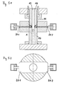
- Fig. 1 shows a shock absorber piston 1, which consists of a lower Shock absorber piston part 2 and an upper shock absorber piston part 3 exists.
- a shock absorber piston 1 In the middle of the shock absorber piston 1 there is a cylindrical bore 4. Also points the shock absorber piston 1 through channels 6, which him in enforce essentially in the axial direction.
- the one on the Circumferential surface of the shock absorber piston 1 arranged annular groove 5 is due to the undercut of the shock absorber piston parts 2 and 3 formed and must be made to their final dimensions will.
- Fig. 2 shows a three-part shock absorber piston 1, which a center sleeve 7, and a same upper 8 and lower Shock absorber piston part 9.
- the on the peripheral surface the shock absorber piston 1 arranged annular groove 5 is by the undercut of the shock absorber piston parts 8 and 9 is formed and must also be made to measure.
- Fig. 3 shows a two-part shock absorber piston 1, based on which is the precise final production by calibrating the Ring groove 5 in FIGS. 4.1 to 6.2 is explained below.
- This shock absorber piston 1 consists of two different shock absorber piston parts, namely the upper shock piston part 10 and the lower shock piston part 11. Furthermore the shock absorber piston 1 through channels 6 and an annular groove 5 on its peripheral surface, the annular groove 5 mainly in shape through the lower shock piston part 11 is formed and the upper shock piston part 10 forms the lateral boundary of the annular groove 5.
- the shock absorber piston 1 which consists of the upper 10 and lower shock absorber piston part 11 exists, can be added. This can be done manually or for example also by means of an automatic joining device be performed.
- the pre-assembled shock absorber piston 1 is then inserted into a calibration matrix 12, which is limited by a lower die 17.
- the lower die 17 is an upper die 18 with assigned a sleeve-like stamp 14.
- the shock absorber piston 1 is by means of a pre-pressure of the leading Stamp 14 added to the piston shirt 15.
- the joining the shock absorber piston 1 can also by means of the leading sleeve-like stamp 14 and / or by means of the upper Form stamp 18 are performed.
- the upper form stamp 18, the leading, rifle-like stamp 14 and the lower one Form stamps 17 correspond to the surface of the upper one 19 and lower shock absorber piston part 16 profiled.
- the calibration slide 20 correspond in its outer, engaging in the annular groove 5 Dimensions the desired production dimension of the ring groove.
- the calibration allowance provided on the sintered component from approx. 1 to 10% in height due to plastic deformation reduced, so that in particular the annular groove 5 the desired Receives final dimensions.
- the inner stamp 18 mainly delivers all other dimensions It is of particular importance that the Ring groove width to which dimension a is calibrated and the upper one 21 and lower 22 ring groove flank after calibration in parallel are to each other and the gauge block for the ring groove diameter b is reached.
- the sintered and joined Shock absorber piston 1 slightly the groove width larger and the ring groove diameter designed slightly smaller are.
- the calibration slide 20 By pressing on the die Shock absorber piston 1, in its annular groove 5, the calibration slide 20 intervene, the annular groove width is due to partial deformations a and the ring groove diameter b brought to the final dimension and the parallelism of the ring groove flanks 21, 22 ensures.
- 6.1 and 6.2 show the demolding step. For this the calibration slide 20 from the calibrated ring groove 5 removed and the shock absorber piston 1 through the lower Stamp 17 ejected from the die 13.
Landscapes
- Engineering & Computer Science (AREA)
- Manufacturing & Machinery (AREA)
- Mechanical Engineering (AREA)
- Pistons, Piston Rings, And Cylinders (AREA)
- Measuring Fluid Pressure (AREA)
Applications Claiming Priority (2)
| Application Number | Priority Date | Filing Date | Title |
|---|---|---|---|
| DE19635183A DE19635183A1 (de) | 1996-08-30 | 1996-08-30 | Verfahren zur Kalibrierung einer vorgeformten Ausnehmung |
| DE19635183 | 1996-08-30 |
Publications (2)
| Publication Number | Publication Date |
|---|---|
| EP0826450A1 true EP0826450A1 (fr) | 1998-03-04 |
| EP0826450B1 EP0826450B1 (fr) | 2001-02-28 |
Family
ID=7804177
Family Applications (1)
| Application Number | Title | Priority Date | Filing Date |
|---|---|---|---|
| EP97114049A Expired - Lifetime EP0826450B1 (fr) | 1996-08-30 | 1997-08-14 | Procédé de calibration d'un évidement |
Country Status (4)
| Country | Link |
|---|---|
| US (1) | US6101713A (fr) |
| EP (1) | EP0826450B1 (fr) |
| DE (2) | DE19635183A1 (fr) |
| ES (1) | ES2155643T3 (fr) |
Families Citing this family (7)
| Publication number | Priority date | Publication date | Assignee | Title |
|---|---|---|---|---|
| DE102010009800B3 (de) * | 2010-03-01 | 2011-06-16 | Gkn Sinter Metals Holding Gmbh | Verfahren zum Hochgenauigkeitskalibrieren eines Bauteils |
| DE102013201962B4 (de) * | 2013-02-06 | 2016-08-18 | Schwäbische Hüttenwerke Automotive GmbH | Sinterbauteil mit Verstemmwulst |
| AT513616B1 (de) | 2013-05-28 | 2014-06-15 | Miba Sinter Austria Gmbh | Verfahren zum Verschließen einer Bohrung |
| DE102013015676A1 (de) | 2013-09-23 | 2015-03-26 | Gkn Sinter Metals Holding Gmbh | Verfahren zur Herstellung eines Sinterteils mit höhenpräziser Formteilhöhe sowie Teilesatz aus Sinterfügeteilen |
| DE102013015677A1 (de) * | 2013-09-23 | 2015-03-26 | Gkn Sinter Metals Holding Gmbh | Verfahren zur Herstellung eines Sinterteils mit hochgenauer radialer Präzision sowie Teilesatz mit Sinterfügeteilen |
| EP3263249B1 (fr) * | 2016-06-30 | 2019-01-23 | Seco Tools Ab | Outil de compression |
| DE102019134153A1 (de) * | 2019-12-12 | 2021-06-17 | Gkn Sinter Metals Engineering Gmbh | Sinterteil und Verfahren zu dessen Herstellung |
Citations (4)
| Publication number | Priority date | Publication date | Assignee | Title |
|---|---|---|---|---|
| FR1490434A (fr) * | 1966-08-29 | 1967-07-28 | Federal Mogul Corp | Procédé de fabrication de pièces compliquées en poudre frittée |
| DE2854079A1 (de) * | 1978-12-14 | 1980-07-03 | Federal Mogul Corp | Verfahren zum schmieden eines werkstueckes mit zurueckspringenden oberflaechenabschnitten |
| DE4118040A1 (de) * | 1991-06-01 | 1992-12-03 | Glyco Metall Werke | Verfahren zur herstellung eines sintermetall- oder gesenkschmiede-fertigteils |
| EP0557548A1 (fr) * | 1992-02-26 | 1993-09-01 | Ringsdorff Sinter GmbH | Piston d'amortisseur multi-pièce par ajustage |
Family Cites Families (14)
| Publication number | Priority date | Publication date | Assignee | Title |
|---|---|---|---|---|
| US6683A (en) * | 1849-08-28 | And john w | ||
| US2089790A (en) * | 1935-07-24 | 1937-08-10 | Texas Co | Method of forming a rolled joint |
| US2294095A (en) * | 1940-02-07 | 1942-08-25 | John W Pease | Wooden ladder construction |
| US2446621A (en) * | 1943-12-03 | 1948-08-10 | Gen Tire & Rubber Co | Method of making precision antivibration mountings |
| US2388953A (en) * | 1944-07-01 | 1945-11-13 | Joseph C Coombs | Spark plug gap adjuster |
| US2501826A (en) * | 1945-04-06 | 1950-03-28 | Frederick I Mccarthy | Spark plug |
| US2610686A (en) * | 1947-08-23 | 1952-09-16 | Krasberg Rudolf | Automatic stop for dies |
| US2627120A (en) * | 1950-11-15 | 1953-02-03 | Timken Roller Bearing Co | Spacer gauge for adjustable roller bearings |
| DE1265993B (de) * | 1962-01-18 | 1968-04-11 | Driam A G | Vorrichtung zum Messen der Schweissspaltbreite bei der Herstellung von Schraubennahtrohren |
| US3209437A (en) * | 1962-04-13 | 1965-10-05 | Voorhies Carl | Method of securing together two members |
| US3255521A (en) * | 1964-07-13 | 1966-06-14 | Crawford Fitting Co | Method of assembly |
| GB1145592A (en) * | 1967-01-16 | 1969-03-19 | Crestshore Engineering Ltd | Template for use in measuring pipework |
| US3834212A (en) * | 1972-12-11 | 1974-09-10 | Wallance Expanding Machines In | Apparatus for forming metal wheels |
| JPS5911779B2 (ja) * | 1976-09-13 | 1984-03-17 | 豊生ブレ−キ工業株式会社 | ドラムブレ−キ用ストラツト部材の製造方法 |
-
1996
- 1996-08-30 DE DE19635183A patent/DE19635183A1/de not_active Withdrawn
-
1997
- 1997-08-14 ES ES97114049T patent/ES2155643T3/es not_active Expired - Lifetime
- 1997-08-14 EP EP97114049A patent/EP0826450B1/fr not_active Expired - Lifetime
- 1997-08-14 DE DE59703037T patent/DE59703037D1/de not_active Expired - Lifetime
- 1997-08-29 US US08/921,112 patent/US6101713A/en not_active Expired - Lifetime
Patent Citations (4)
| Publication number | Priority date | Publication date | Assignee | Title |
|---|---|---|---|---|
| FR1490434A (fr) * | 1966-08-29 | 1967-07-28 | Federal Mogul Corp | Procédé de fabrication de pièces compliquées en poudre frittée |
| DE2854079A1 (de) * | 1978-12-14 | 1980-07-03 | Federal Mogul Corp | Verfahren zum schmieden eines werkstueckes mit zurueckspringenden oberflaechenabschnitten |
| DE4118040A1 (de) * | 1991-06-01 | 1992-12-03 | Glyco Metall Werke | Verfahren zur herstellung eines sintermetall- oder gesenkschmiede-fertigteils |
| EP0557548A1 (fr) * | 1992-02-26 | 1993-09-01 | Ringsdorff Sinter GmbH | Piston d'amortisseur multi-pièce par ajustage |
Also Published As
| Publication number | Publication date |
|---|---|
| ES2155643T3 (es) | 2001-05-16 |
| DE59703037D1 (de) | 2001-04-05 |
| US6101713A (en) | 2000-08-15 |
| DE19635183A1 (de) | 1998-03-05 |
| EP0826450B1 (fr) | 2001-02-28 |
Similar Documents
| Publication | Publication Date | Title |
|---|---|---|
| EP2060346B1 (fr) | Outil d'étanchéité, dispositif de compactage comprenant cet outil et procédé pour la compactage d'une pièce frittée ou de poudres | |
| DE10150613B4 (de) | Radlagereinheit für Kraftfahrzeuge | |
| DE2219856B2 (de) | Verfahren zum Herstellen von in einem Arbeitsgang geschmiedeten Sinterschmiedewerkstücken | |
| EP1133374B1 (fr) | Procede pour la production d'une piece frittee avec formage ulterieur de l'ebauche | |
| EP1543254B8 (fr) | Element de piston fabrique selon une technique de metallurgie des poudres et dote d'entretoises d'appui, et procede de fabrication associe | |
| WO2015039747A1 (fr) | Procédé permettant de produire une pièce frittée d'une hauteur de pièce moulée précise et ensemble de pièces composé de pièces frittées assemblées | |
| DE19508632C2 (de) | Verfahren zum Verbinden eines ersten Bauteiles mit einem zweiten Bauteil | |
| DE3936438A1 (de) | Extrudergehaeusebauteil fuer einen zweischneckenextruder und verfahren zur herstellung | |
| DE3515180A1 (de) | Verfahren und vorrichtung zum herstellen einer flanschenbuchse | |
| DE19508952C2 (de) | Preßvorrichtung zur Erzeugung eines Formteils und entsprechendes Formteil | |
| DE3110756A1 (de) | Verfahren zur herstellung einer aluminiumfelge | |
| EP0826450B1 (fr) | Procédé de calibration d'un évidement | |
| DE2733925C2 (de) | Verfahren zum Herstellen von Verbundfließpreßkörpern | |
| EP0266712B1 (fr) | Procédé et appareil de fabrication d'éléments de friction, notamment pour corps de synchronisation dans des transmissions de véhicule | |
| DE102015210588A1 (de) | Verfahren und Vorrichtung zum Pressen eines Grünlings | |
| EP0682999B1 (fr) | Article moulé, procédé et installation pour sa préparation | |
| DE19909821A1 (de) | Niet zum Fügen von Werkstücken | |
| DE10314544A1 (de) | Formschüssige Fügeverbindung | |
| DE2953354C2 (de) | Verfahren zum Herstellen eines inneren Gelenkkörpers für ein homokinetisches Gelenk | |
| DE3816090C2 (fr) | ||
| DE2544325A1 (de) | Plastisches formverfahren fuer metalle | |
| DE1813448A1 (de) | Verfahren und Vorrichtung zum Verbinden von kleinen Bauteilen mit einer Grundplatte aus superplastischem Metall | |
| EP0579005B1 (fr) | Procédé, dispositif et matrice pour la fabrication d'une pièce ayant une section profilée | |
| DE102018217822B3 (de) | Verfahren zur Herstellung mindestens einer Verzahnung an einem Bauteil und Werkzeug zur Durchführung des Verfahrens | |
| DE3724000A1 (de) | Verfahren und vorrichtung zum herstellen von reibschluessigen elementen, insbesondere von synchronisierungskoerpern in stufengetrieben von kraftfahrzeugen |
Legal Events
| Date | Code | Title | Description |
|---|---|---|---|
| PUAI | Public reference made under article 153(3) epc to a published international application that has entered the european phase |
Free format text: ORIGINAL CODE: 0009012 |
|
| AK | Designated contracting states |
Kind code of ref document: A1 Designated state(s): DE ES FR GB IT |
|
| 17P | Request for examination filed |
Effective date: 19980513 |
|
| AKX | Designation fees paid |
Free format text: DE ES FR GB IT |
|
| RBV | Designated contracting states (corrected) |
Designated state(s): DE ES FR GB IT |
|
| RAP1 | Party data changed (applicant data changed or rights of an application transferred) |
Owner name: GKN SINTER METALS HOLDING GMBH |
|
| GRAG | Despatch of communication of intention to grant |
Free format text: ORIGINAL CODE: EPIDOS AGRA |
|
| RAP1 | Party data changed (applicant data changed or rights of an application transferred) |
Owner name: GKN SINTER METALS GMBH |
|
| GRAG | Despatch of communication of intention to grant |
Free format text: ORIGINAL CODE: EPIDOS AGRA |
|
| GRAH | Despatch of communication of intention to grant a patent |
Free format text: ORIGINAL CODE: EPIDOS IGRA |
|
| 17Q | First examination report despatched |
Effective date: 20000727 |
|
| GRAH | Despatch of communication of intention to grant a patent |
Free format text: ORIGINAL CODE: EPIDOS IGRA |
|
| GRAA | (expected) grant |
Free format text: ORIGINAL CODE: 0009210 |
|
| AK | Designated contracting states |
Kind code of ref document: B1 Designated state(s): DE ES FR GB IT |
|
| GBT | Gb: translation of ep patent filed (gb section 77(6)(a)/1977) |
Effective date: 20010228 |
|
| REF | Corresponds to: |
Ref document number: 59703037 Country of ref document: DE Date of ref document: 20010405 |
|
| ITF | It: translation for a ep patent filed |
Owner name: BARZANO' E ZANARDO ROMA S.P.A. |
|
| ET | Fr: translation filed | ||
| REG | Reference to a national code |
Ref country code: ES Ref legal event code: FG2A Ref document number: 2155643 Country of ref document: ES Kind code of ref document: T3 |
|
| REG | Reference to a national code |
Ref country code: GB Ref legal event code: IF02 |
|
| PLBE | No opposition filed within time limit |
Free format text: ORIGINAL CODE: 0009261 |
|
| STAA | Information on the status of an ep patent application or granted ep patent |
Free format text: STATUS: NO OPPOSITION FILED WITHIN TIME LIMIT |
|
| 26N | No opposition filed | ||
| PGFP | Annual fee paid to national office [announced via postgrant information from national office to epo] |
Ref country code: FR Payment date: 20090819 Year of fee payment: 13 Ref country code: ES Payment date: 20090821 Year of fee payment: 13 |
|
| PGFP | Annual fee paid to national office [announced via postgrant information from national office to epo] |
Ref country code: GB Payment date: 20090821 Year of fee payment: 13 |
|
| PGFP | Annual fee paid to national office [announced via postgrant information from national office to epo] |
Ref country code: IT Payment date: 20090824 Year of fee payment: 13 |
|
| GBPC | Gb: european patent ceased through non-payment of renewal fee |
Effective date: 20100814 |
|
| REG | Reference to a national code |
Ref country code: FR Ref legal event code: ST Effective date: 20110502 |
|
| PG25 | Lapsed in a contracting state [announced via postgrant information from national office to epo] |
Ref country code: IT Free format text: LAPSE BECAUSE OF NON-PAYMENT OF DUE FEES Effective date: 20100814 |
|
| PG25 | Lapsed in a contracting state [announced via postgrant information from national office to epo] |
Ref country code: FR Free format text: LAPSE BECAUSE OF NON-PAYMENT OF DUE FEES Effective date: 20100831 |
|
| PG25 | Lapsed in a contracting state [announced via postgrant information from national office to epo] |
Ref country code: GB Free format text: LAPSE BECAUSE OF NON-PAYMENT OF DUE FEES Effective date: 20100814 |
|
| REG | Reference to a national code |
Ref country code: ES Ref legal event code: FD2A Effective date: 20111019 |
|
| PG25 | Lapsed in a contracting state [announced via postgrant information from national office to epo] |
Ref country code: ES Free format text: LAPSE BECAUSE OF NON-PAYMENT OF DUE FEES Effective date: 20100815 |
|
| REG | Reference to a national code |
Ref country code: DE Ref legal event code: R082 Ref document number: 59703037 Country of ref document: DE Representative=s name: KNH PATENTANWAELTE KAHLHOEFER NEUMANN ROESSLER, DE Ref country code: DE Ref legal event code: R082 Ref document number: 59703037 Country of ref document: DE Representative=s name: VON KREISLER SELTING WERNER - PARTNERSCHAFT VO, DE |
|
| REG | Reference to a national code |
Ref country code: DE Ref legal event code: R082 Ref document number: 59703037 Country of ref document: DE Representative=s name: KNH PATENTANWAELTE KAHLHOEFER NEUMANN ROESSLER, DE |
|
| PGFP | Annual fee paid to national office [announced via postgrant information from national office to epo] |
Ref country code: DE Payment date: 20160823 Year of fee payment: 20 |
|
| REG | Reference to a national code |
Ref country code: DE Ref legal event code: R071 Ref document number: 59703037 Country of ref document: DE |