EP0825083A1 - Soufflet d'intercirculation pour matériel roulant - Google Patents
Soufflet d'intercirculation pour matériel roulant Download PDFInfo
- Publication number
- EP0825083A1 EP0825083A1 EP97401595A EP97401595A EP0825083A1 EP 0825083 A1 EP0825083 A1 EP 0825083A1 EP 97401595 A EP97401595 A EP 97401595A EP 97401595 A EP97401595 A EP 97401595A EP 0825083 A1 EP0825083 A1 EP 0825083A1
- Authority
- EP
- European Patent Office
- Prior art keywords
- bellows
- module
- regions
- bellows according
- region
- Prior art date
- Legal status (The legal status is an assumption and is not a legal conclusion. Google has not performed a legal analysis and makes no representation as to the accuracy of the status listed.)
- Granted
Links
Images

Classifications
-
- B—PERFORMING OPERATIONS; TRANSPORTING
- B61—RAILWAYS
- B61D—BODY DETAILS OR KINDS OF RAILWAY VEHICLES
- B61D17/00—Construction details of vehicle bodies
- B61D17/04—Construction details of vehicle bodies with bodies of metal; with composite, e.g. metal and wood body structures
- B61D17/20—Communication passages between coaches; Adaptation of coach ends therefor
- B61D17/22—Communication passages between coaches; Adaptation of coach ends therefor flexible, e.g. bellows
-
- Y—GENERAL TAGGING OF NEW TECHNOLOGICAL DEVELOPMENTS; GENERAL TAGGING OF CROSS-SECTIONAL TECHNOLOGIES SPANNING OVER SEVERAL SECTIONS OF THE IPC; TECHNICAL SUBJECTS COVERED BY FORMER USPC CROSS-REFERENCE ART COLLECTIONS [XRACs] AND DIGESTS
- Y10—TECHNICAL SUBJECTS COVERED BY FORMER USPC
- Y10T—TECHNICAL SUBJECTS COVERED BY FORMER US CLASSIFICATION
- Y10T29/00—Metal working
- Y10T29/49—Method of mechanical manufacture
- Y10T29/49826—Assembling or joining
- Y10T29/49877—Assembling or joining of flexible wall, expansible chamber devices [e.g., bellows]
Definitions
- the subject of the present invention is a bellows for rolling stock, intended by example to ensure the connection between two cars of a mobile assembly such as a train, a tram, a bus, or any other rail or road vehicle.
- Some known devices use a riveted configuration made of leather with like reinforcements of aluminum profiles, while others are made on the basis of a coated fabric on both sides of polyvinyl chloride (PVC), or rubber, then cut, assembled by gluing and sewing and finally reinforced on the outer contour of the waves by a bent and crimped aluminum profile.
- PVC polyvinyl chloride
- the problem therefore exists of providing a bellows of connection against bad weather, in particular for a railway car, ensuring watertightness and to absorb the travel between cars while maintaining a developable geometry for guarantee a good service life.
- a general object of the present invention is to bring an advantageous solution to this problem.
- an interconnection bellows for rolling stock having wavy regions forming a deformable volume, characterized in that it comprises a plurality of modules assembled together, each module being made of a material based on a elastomer such as rubber and comprising at least two wavy regions joined together by vulcanization.
- This vulcanization assembly presents in besides the important advantage of avoiding the presence of seams which affect waterproofing on the one hand and part constitute dirt retention zones.
- the bellows is advantageously characterized by that at least one module has at least one element of reinforcement housed inside at least one stiffener of the module, said stiffener being constituted by a frame having a larger section than the rest of the module, said stiffener being located in the extension of the outer end of at least one wavy region.
- said stiffener connects two wavy regions of the module, when the module is not a module end.
- Said frame may include at least one recess making it possible to house at least one said element of reinforcement.
- Said reinforcing element is preferably a glass and resin rod, especially epoxy.
- Said stiffener may have a surface external forming an external contour of the form module general rectangular.
- the reinforcement (s) are advantageously arranged only in regions substantially straight.
- the bellows is characterized in that the modules constituting the bellows have a said frame stiffener located at each of their ends longitudinal and in that said end frames are delimited longitudinally by regions of closed outline and in that said modules are assembled between them at least one end by said frames end for example using screws so that press said contour regions against each other closed.
- Said closed contour regions can have complementary sawtooth profiles, to ensure a good seal.
- the process is characterized in that the module blank has at least one stiffener forming a frame stiffener having a cross section greater than that of the rest of the blank, said stiffening frame connecting two said wavy regions, and in that at least one element of reinforcement is housed inside the stiffener frame.
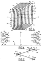
- the interconnection bellows shown in Figure 1 is a bellows 40 connecting between two cars with a number of wavy regions or waves 2 vulcanized in shape, seamless or collage.
- each wave is in the form of an inclined frame 2 which presents in section a substantially planar section, inclined at an angle a to the normal to the axis longitudinal XX 'of the bellows.
- the edge 21 of the frame 2 which is directed towards the inside of the bellows 40 extends by a planar region 20 of closed contour which is vulcanized with the flat region 20 of wave 2 which is adjacent.
- the module shown in Figure 1b comprises, for example, six wavy regions 2.
- the edge 22 of the frame 2 which is directed towards the outside of the bellows 40 is extended by a stiffener exterior 3 which is common to two adjacent frames 2.
- the stiffener 3 has a clearly marked section greater than that of regions 2, while frames 2 constitute flexible waves making it possible to ensure the displacements sought. In this way the stiffeners 3 of the bellows 40 retain their shape during deformation frames 2.
- Said external stiffener 3 has preferably reinforcing elements 1 such as one or several epoxy glass rods which are housed in the external stiffener 3, which are for example drowned therein, in particular with adhesion to the material constituting the external reinforcement 3, or else fixed thereon, for example by being arranged in recesses provided for this purpose.
- the external stiffener 3 forms a frame exterior of axis XX 'of generally rectangular shape outer contour 35 and having parts substantially straight 10, 12 and 14 interconnected by corner regions 11. Reinforcements 1, are of preferably arranged only in parts substantially straight 10, 12 and 14.
- the reinforcement (s) 1 according to the invention allow to overcome wave reinforcements by Aluminum of the Prior Art. Such reinforcements in aluminum which are bent and crimped, are complicated work.
- the bellows 40 is made from modules 50 placed end to end and assembled for example by screws 6, at external end stiffeners 30.
- the frames 2 which form the central part of the wave, the flat regions 20 and the external stiffeners 3 and 30 are made in vulcanized elastomer, for example rubber, and more particularly in vulcanized rubberized fabric, the waves 2 being joined together by vulcanization, this vulcanization ensuring mechanical cohesion and tightness at the level of the frames 2 and the stiffeners exteriors 3.
- Each module 50 can have two end stiffeners 30 delimited longitudinally by regions of closed contour 36 allowing their assembly for example by screws 6. These regions 36 may have additional profiles 31, for example sawtooth, to ensure a seal without having a very large number of fixing screws 6 (figure 3).
- the fixing screws 6 can thus be spaced apart for example 200 to 300 mm.
- Wave 1 reinforcements can be combined to form a very light part, presenting a module of progressive bending according to the characterization of the rods and how they work.
- the wave reinforcement 1 can be the support of the wave and advantageously replace the fabric on its surface to create a wave behaving like "a flat spring ".
- the end fixing can be resumed on a stiffener 32 with dimensions larger than the stiffener 30 and which is adhered to the end frame 2 ' and drilled in 38 for fixing on the body of the car (see Figure 1b).
- each end may consist of a metal cable fixed on the wave, outside or inside of it for secure the bellows on a profile provided for this effect.
- the bellows 40 in its set consists of 2 or 3, even 4, 50 modules which are molded, vulcanized and which are assembled by this system where the mark 30 constitutes the molded rubber stiffener with its reinforcements glass-resin 5, the assembly consisting of modules C and D being assembled here by means of screws 6 (figure 3).
- FIG. 1 represents a bellows 40 consisting of two modules 50.
- the entire frame 2 can be made on the basis of a ply 7 of rushes of epoxy glass to ensure great vertical stiffness at frame 2 while retaining its possibilities of deformation.
- This rush sheet includes for example strings of epoxy glass thread spaced one step apart example from 5 to 10 mm and joined together by weft threads to form the web 7.
- the corner regions 11 can also be provided with a ply 7.
- the web 7 which constitutes the reinforcement is embedded in the rubber.
- the present invention applies also to give stiffness to the joints sealing molded or extruded.
- the bellows according to the invention may have one end a seal 55 molded or extruded which is then adhered (or glued) to the bellows.
- a way preferred embodiment of this joint is shown in Figure 5. It has a reinforcement region 58 in which are preferably drowned one or more reinforcing elements 8, for example one or more rods glass-resin, and a lip 9 intended to ensure sealing.
Abstract
Description
- disposer dans un moule des feuilles de caoutchouc non vulcanisé pour former une ébauche de module présentant au moins deux régions ondulées,
- vulcaniser l'ébauche de module pour obtenir un module présentant au moins deux régions ondulées assemblées entre elles par vulcanisation,
- assembler mécaniquement une pluralité des dits modules pour former le soufflet.
- la figure la représente, en perspective, un soufflet d'intercirculation selon l'invention ;
- la figure 1b représente une coupe d'un module selon l'invention par un plan horizontal passant par l'axe XX' ;
- la figure 2 représente une coupe d'un module selon l'invention, comportant un raidisseur extérieur ;
- la figure 3 illustre l'assemblage de deux modules selon l'invention ;
- la figure 4 représente une variante du module selon l'invention ;
- et la figure 5 représente en coupe un profilé caoutchouc équipé d'un raidisseur selon une variante de l'invention.
Claims (14)
- Soufflet d'intercirculation pour matériel roulant, présentant des régions ondulées formant un volume déformable, caractérisé en ce qu'il comporte une pluralité de modules assemblés entre eux, chaque module étant réalisé en un matériau à base de caoutchouc et comportant au moins deux régions ondulées (2) assemblées entre elles par vulcanisation.
- Soufflet selon la revendication 1, caractérisé en ce qu'au moins un module comporte au moins un élément de renfort (1) logé à l'intérieur d'au moins un raidisseur (3, 30, 32) du module, ledit raidisseur (3, 30, 32) formant un cadre raidisseur ayant une section supérieure à celle du reste du module, ledit raidisseur étant situé dans le prolongement de l'extrémité extérieure d'au moins une région ondulée du module.
- Soufflet selon la revendication 2, caractérisé en ce que ledit cadre raidisseur (3, 30, 32) comporte au moins un évidement permettant de loger au moins un dit élément de renfort (1).
- Soufflet selon une des revendications 2 ou 3, caractérisé en ce que ledit élément de renfort (1) est un jonc en verre époxy.
- Soufflet selon une des revendications 2 à 4, caractérisé en ce que ledit cadre raidisseur (3, 30, 32) présente des régions sensiblement rectilignes (10, 12) raccordées entre elles par les régions de coin (11).
- Soufflet selon la revendication 5, caractérisé en ce que le ou les éléments de renfort (1) sont disposés uniquement dans les régions sensiblement rectilignes (10, 12).
- Soufflet selon une des revendications 2 à 6, caractérisé en ce que les modules constituant le soufflet présentent un dit cadre raidisseur (30) situé à chacune de leurs extrémités longitudinales et en ce que ledits cadres d'extrémité (30, 32) sont délimités longitudinalement par des régions de contour fermé (36) et en ce que ledits modules sont assemblés entre eux à au moins une extrémité par ledits cadres d'extrémité (30) de manière à appuyer l'une contre l'autre lesdites régions de contour fermé (36).
- Soufflet selon une des revendications précédentes, caractérisé en ce qu'il comporte un tissu ou une nappe de joncs tramée (7) noyée dans ledit matériau à base de caoutchouc au moins dans une zone du module.
- Soufflet selon la revendication 8, caractérisé en ce qu'une dite zone est une dite région de coin (11).
- Soufflet selon une des revendications précédentes, caractérisé en ce que les régions de contour fermé (36) présentent des profils complémentaires en dents de scie (31).
- Soufflet selon une des revendications précédentes, caractérisé en ce qu'il présente à une extrémité un joint d'étanchéité (55).
- Soufflet selon la revendication 1, caractérisé en ce que ce joint présente une première région dans laquelle est noyé au moins un élément de renfort (8) et une deuxième région (9) formant une lèvre d'étanchéité.
- Procédé de réalisation d'un soufflet d'interconnexion, caractérisé en ce qu'il comporte les étapes suivantes :disposer dans un moule des feuilles de caoutchouc non vulcanisé pour former une ébauche de module présentant au moins deux régions ondulées,vulcaniser l'ébauche de module pour obtenir un module présentant au moins deux régions ondulées assemblées entre elles par vulcanisation,assembler mécaniquement une pluralité des dits modules pour former le soufflet.
- Procédé selon la revendication 13, caractérisé en ce que l'ébauche de module présente au moins une région formant un cadre raidisseur ayant une section supérieure à celle du reste de l'ébauche, ladite région formant cadre reliant deux dites régions ondulées, et en ce qu'au moins un élément de renfort est logé à l'intérieur de ladite région formant cadre.
Applications Claiming Priority (2)
| Application Number | Priority Date | Filing Date | Title |
|---|---|---|---|
| FR9608932 | 1996-07-17 | ||
| FR9608932A FR2751291B1 (fr) | 1996-07-17 | 1996-07-17 | Soufflet d'intercirculation pour materiel roulant |
Publications (2)
| Publication Number | Publication Date |
|---|---|
| EP0825083A1 true EP0825083A1 (fr) | 1998-02-25 |
| EP0825083B1 EP0825083B1 (fr) | 2001-06-06 |
Family
ID=9494137
Family Applications (1)
| Application Number | Title | Priority Date | Filing Date |
|---|---|---|---|
| EP97401595A Expired - Lifetime EP0825083B1 (fr) | 1996-07-17 | 1997-07-04 | Soufflet d'intercirculation pour matériel roulant |
Country Status (6)
| Country | Link |
|---|---|
| US (2) | US5953998A (fr) |
| EP (1) | EP0825083B1 (fr) |
| JP (1) | JPH1081233A (fr) |
| DE (1) | DE69705093T2 (fr) |
| ES (1) | ES2159092T3 (fr) |
| FR (1) | FR2751291B1 (fr) |
Families Citing this family (15)
| Publication number | Priority date | Publication date | Assignee | Title |
|---|---|---|---|---|
| KR200230783Y1 (ko) * | 2001-02-23 | 2001-07-19 | 박수정 | 철도 차량용 연결막 |
| US6840529B2 (en) * | 2002-10-17 | 2005-01-11 | David B. Call | Articulated pickup truck camper/trailer |
| US20040133411A1 (en) * | 2003-01-08 | 2004-07-08 | Derrick Babb | Automated Transit System |
| DE102005005621B4 (de) * | 2005-02-08 | 2009-01-08 | Hübner GmbH | Balg eines Übergangs zwischen zwei gelenkig miteinander verbundenen Fahrzeugen oder Balg einer Fluggastbrücke |
| IT1390798B1 (it) * | 2008-07-31 | 2011-10-19 | Pei Protezioni Elaborazioni | Dispositivo di collegamento tra il soffietto ed il telaio di veicoli articolati. |
| DE102009023823B4 (de) * | 2009-06-04 | 2011-02-17 | Hübner GmbH | Balg zwischen zwei gelenkig miteinander verbundenen Fahrzeugen oder Balg einer Fluggasttreppe oder -brücke |
| WO2011019766A2 (fr) * | 2009-08-11 | 2011-02-17 | Draggone Aerodynamics, Inc. | Dispositif permettant d'améliorer l'aérodynamique d'un semi-remorque dans l'espace vide entre le tracteur et la remorque |
| DE102010005250B4 (de) * | 2010-01-20 | 2013-03-21 | Db Fernverkehr Ag | Schienenfahrzeug für einen Fahrbetrieb auf Gleisanlagen mit Schotter-Oberbau |
| US8733777B2 (en) * | 2010-02-05 | 2014-05-27 | HÜBNER GmbH & Co. KG | Corrugation bellows of a transfer between two pivotably interconnected vehicles |
| ES2539037T3 (es) * | 2010-02-05 | 2015-06-25 | HÜBNER GmbH & Co. KG | Fuelle ondulado de un paso entre dos vehículos conectados de modo articulado entre ellos |
| CA2858516A1 (fr) * | 2013-08-06 | 2015-02-06 | A&A Manufacturing Co., Inc. | Soufflet pour vehicule articule |
| KR102073127B1 (ko) * | 2018-06-28 | 2020-02-04 | 조성암 | 압출 펌핑모듈 및 이를 이용한 다아이프램 도료공급장치 |
| CN110869612A (zh) * | 2018-06-28 | 2020-03-06 | 曹瑆岩 | 挤压抽吸模块及利用其的隔膜式流体供给装置 |
| KR102073119B1 (ko) * | 2018-06-28 | 2020-02-04 | 조성암 | 압출 펌핑모듈 및 이를 이용한 다아이프램 도료공급장치 |
| EP4108430A1 (fr) * | 2021-06-24 | 2022-12-28 | Hübner GmbH & Co. KG | Procédé de fabrication d'une section de paroi de recouvrement d'un recouvrement flexible, ainsi que recouvrement doté d'une paroi de recouvrement composée de l'au moins une section de paroi de recouvrement fabriquée selon le procédé |
Citations (3)
| Publication number | Priority date | Publication date | Assignee | Title |
|---|---|---|---|---|
| FR914247A (fr) * | 1945-04-06 | 1946-10-02 | Soufflet d'intercommunication entre les voitures de chemin de fer et procédés de fabrication | |
| FR2328141A1 (fr) * | 1975-10-16 | 1977-05-13 | Taurus Gumiipari Vallalat | Soufflet flexible a plis a base d'un complexe textile-elastomere |
| DE3612425A1 (de) * | 1986-04-12 | 1987-10-15 | Huebner Gummi & Kunststoff | Uebergangsschutz |
Family Cites Families (7)
| Publication number | Priority date | Publication date | Assignee | Title |
|---|---|---|---|---|
| US2282063A (en) * | 1938-10-07 | 1942-05-05 | Us Rubber Co | Railroad passenger car |
| US2534124A (en) * | 1945-03-22 | 1950-12-12 | Cook Electric Co | Method of fabricating bellows |
| US2408473A (en) * | 1945-06-21 | 1946-10-01 | Clarence P Nelson | Dust seal for adjoining railroad cars |
| DE2617931C2 (de) * | 1976-04-23 | 1984-06-14 | Hübner Gummi- und Kunststoff GmbH, 3500 Kassel | Faltenbalg |
| DE3309898A1 (de) * | 1983-03-18 | 1984-09-20 | Hübner Gummi- und Kunststoff GmbH, 3500 Kassel | Vorrichtung zum abdecken des verschlusses von faltenbaelgen |
| FR2629034B1 (fr) * | 1988-03-25 | 1990-04-20 | Caoutchouc Manuf Plastique | Membrane deformable pour tunnel d'intercirculation entre vehicules successifs ferroviaires ou routiers |
| FR2645097B1 (fr) * | 1989-03-28 | 1991-06-21 | Caoutchouc Manuf Plastique | Membrane deformable pour tunnel d'intercirculation entre vehicules successifs ferroviaires ou routiers a ondes de profondeur croissante |
-
1996
- 1996-07-17 FR FR9608932A patent/FR2751291B1/fr not_active Expired - Fee Related
-
1997
- 1997-07-04 DE DE69705093T patent/DE69705093T2/de not_active Expired - Fee Related
- 1997-07-04 ES ES97401595T patent/ES2159092T3/es not_active Expired - Lifetime
- 1997-07-04 EP EP97401595A patent/EP0825083B1/fr not_active Expired - Lifetime
- 1997-07-16 US US08/893,984 patent/US5953998A/en not_active Expired - Fee Related
- 1997-07-17 JP JP9192802A patent/JPH1081233A/ja active Pending
-
1999
- 1999-06-30 US US09/343,465 patent/US6085403A/en not_active Expired - Fee Related
Patent Citations (3)
| Publication number | Priority date | Publication date | Assignee | Title |
|---|---|---|---|---|
| FR914247A (fr) * | 1945-04-06 | 1946-10-02 | Soufflet d'intercommunication entre les voitures de chemin de fer et procédés de fabrication | |
| FR2328141A1 (fr) * | 1975-10-16 | 1977-05-13 | Taurus Gumiipari Vallalat | Soufflet flexible a plis a base d'un complexe textile-elastomere |
| DE3612425A1 (de) * | 1986-04-12 | 1987-10-15 | Huebner Gummi & Kunststoff | Uebergangsschutz |
Also Published As
| Publication number | Publication date |
|---|---|
| FR2751291A1 (fr) | 1998-01-23 |
| DE69705093T2 (de) | 2002-02-07 |
| DE69705093D1 (de) | 2001-07-12 |
| US6085403A (en) | 2000-07-11 |
| EP0825083B1 (fr) | 2001-06-06 |
| US5953998A (en) | 1999-09-21 |
| ES2159092T3 (es) | 2001-09-16 |
| JPH1081233A (ja) | 1998-03-31 |
| FR2751291B1 (fr) | 1998-10-02 |
Similar Documents
| Publication | Publication Date | Title |
|---|---|---|
| EP0825083B1 (fr) | Soufflet d'intercirculation pour matériel roulant | |
| EP2082942B1 (fr) | Soufflet d'intercirculation entre voitures d'un véhicule ferroviaire | |
| EP0390665B1 (fr) | Membrane déformable pour tunnel d'intercirculation entre véhicules successifs ferroviaires ou routiers à ondes de profondeur croissante | |
| CA1329053C (fr) | Membrane deformable pour tunnel d'intercirculation entre vehicules successifs ferroviaires ou routiers | |
| EP0297936B1 (fr) | Dispositif destiné à assurer la continuité de passage entre deux véhicules successifs ferroviaires ou routiers | |
| EP0240407B1 (fr) | Dispositif destiné à assurer la continuité de passage entre deux véhicules successifs ferroviaires ou routiers | |
| JP5272256B2 (ja) | 接着によってその支持部と一体にグレージングを組み立てる方法、及び、この方法を実現するための手段 | |
| FR2529836A1 (fr) | Soufflet elastique autoporteur | |
| FR2569455A1 (fr) | Joint d'etancheite profile permettant d'assembler deux elements de carter a bords paralleles | |
| FR2573714A1 (fr) | Couloir d'intercirculation entre deux voitures de transport en commun | |
| EP0248685A1 (fr) | Joint tubulaire formé de deux membranes roulantes sous faible surpression pour anneau d'intercirculation | |
| EP2758280B1 (fr) | Panneau de protection destine a etre fixe sur une partie de la carrosserie d'un vehicule automobile et vehicule equipe d'un tel panneau | |
| FR2492939A1 (fr) | Garniture tubulaire, en particulier pour l'encadrement de portieres, capots et parties ouvrantes de vehicules automobiles | |
| EP0296901B1 (fr) | Joint d' étanchéité entre un bâti support et un panneau mobile | |
| FR2858287A1 (fr) | Perfectionnement a un dispositif de fixation d'un soufflet d'intercommunication, en particulier pour materiel de transport | |
| FR2980426A1 (fr) | Panneau de protection destine a etre fixe sur une partie de la carrosserie d'un vehicule automobile et vehicule equipe d'un tel panneau | |
| CA2674768A1 (fr) | Systeme de vitrage rigidifie par le collage d'extrusion | |
| KR20130122992A (ko) | 반사지의 훼손방지를 위한 델리네이터 제조방법 | |
| EP1162121A1 (fr) | Dispositif de fixation d'un soufflet et procédé pour sa mise en oeuvre | |
| BE1011654A3 (fr) | Joint d'isolement pour porte, fenetre ou analogue. | |
| EP0442229A1 (fr) | Joint d'étanchéité tubulaire, pour périphérie d'ouverture d'un véhicule | |
| EP1911621A1 (fr) | Joint d'etancheite sur porte pour vehicule | |
| FR2668996A1 (fr) | Soufflet formant protection de passage d'intercommunication pour vehicules articules circulant a grande vitesse. | |
| FR2911311A1 (fr) | Dispositif de fixation pour parement de vehicule automobile et parement associe | |
| CA2860078C (fr) | Vitrage dote de moyens peripheriques d'etancheite et son procede de fabrication |
Legal Events
| Date | Code | Title | Description |
|---|---|---|---|
| PUAI | Public reference made under article 153(3) epc to a published international application that has entered the european phase |
Free format text: ORIGINAL CODE: 0009012 |
|
| AK | Designated contracting states |
Kind code of ref document: A1 Designated state(s): BE DE ES GB IT LU NL SE |
|
| AX | Request for extension of the european patent |
Free format text: AL;LT;LV;RO;SI |
|
| 17P | Request for examination filed |
Effective date: 19980814 |
|
| AKX | Designation fees paid |
Free format text: BE DE ES GB IT LU NL SE |
|
| RBV | Designated contracting states (corrected) |
Designated state(s): BE DE ES GB IT LU NL SE |
|
| GRAG | Despatch of communication of intention to grant |
Free format text: ORIGINAL CODE: EPIDOS AGRA |
|
| 17Q | First examination report despatched |
Effective date: 20000926 |
|
| GRAG | Despatch of communication of intention to grant |
Free format text: ORIGINAL CODE: EPIDOS AGRA |
|
| GRAH | Despatch of communication of intention to grant a patent |
Free format text: ORIGINAL CODE: EPIDOS IGRA |
|
| GRAH | Despatch of communication of intention to grant a patent |
Free format text: ORIGINAL CODE: EPIDOS IGRA |
|
| GRAA | (expected) grant |
Free format text: ORIGINAL CODE: 0009210 |
|
| AK | Designated contracting states |
Kind code of ref document: B1 Designated state(s): BE DE ES GB IT LU NL SE |
|
| REF | Corresponds to: |
Ref document number: 69705093 Country of ref document: DE Date of ref document: 20010712 |
|
| ITF | It: translation for a ep patent filed |
Owner name: STUDIO TORTA S.R.L. |
|
| PGFP | Annual fee paid to national office [announced via postgrant information from national office to epo] |
Ref country code: SE Payment date: 20010806 Year of fee payment: 5 Ref country code: ES Payment date: 20010806 Year of fee payment: 5 |
|
| PGFP | Annual fee paid to national office [announced via postgrant information from national office to epo] |
Ref country code: GB Payment date: 20010808 Year of fee payment: 5 |
|
| PGFP | Annual fee paid to national office [announced via postgrant information from national office to epo] |
Ref country code: NL Payment date: 20010816 Year of fee payment: 5 |
|
| PGFP | Annual fee paid to national office [announced via postgrant information from national office to epo] |
Ref country code: LU Payment date: 20010823 Year of fee payment: 5 Ref country code: DE Payment date: 20010823 Year of fee payment: 5 |
|
| REG | Reference to a national code |
Ref country code: ES Ref legal event code: FG2A Ref document number: 2159092 Country of ref document: ES Kind code of ref document: T3 |
|
| PGFP | Annual fee paid to national office [announced via postgrant information from national office to epo] |
Ref country code: BE Payment date: 20010919 Year of fee payment: 5 |
|
| GBT | Gb: translation of ep patent filed (gb section 77(6)(a)/1977) |
Effective date: 20010904 |
|
| REG | Reference to a national code |
Ref country code: GB Ref legal event code: IF02 |
|
| PLBE | No opposition filed within time limit |
Free format text: ORIGINAL CODE: 0009261 |
|
| STAA | Information on the status of an ep patent application or granted ep patent |
Free format text: STATUS: NO OPPOSITION FILED WITHIN TIME LIMIT |
|
| 26N | No opposition filed | ||
| PG25 | Lapsed in a contracting state [announced via postgrant information from national office to epo] |
Ref country code: LU Free format text: LAPSE BECAUSE OF NON-PAYMENT OF DUE FEES Effective date: 20020704 Ref country code: GB Free format text: LAPSE BECAUSE OF NON-PAYMENT OF DUE FEES Effective date: 20020704 |
|
| PG25 | Lapsed in a contracting state [announced via postgrant information from national office to epo] |
Ref country code: SE Free format text: LAPSE BECAUSE OF NON-PAYMENT OF DUE FEES Effective date: 20020705 Ref country code: ES Free format text: LAPSE BECAUSE OF NON-PAYMENT OF DUE FEES Effective date: 20020705 |
|
| PG25 | Lapsed in a contracting state [announced via postgrant information from national office to epo] |
Ref country code: BE Free format text: LAPSE BECAUSE OF NON-PAYMENT OF DUE FEES Effective date: 20020731 |
|
| BERE | Be: lapsed |
Owner name: *LE JOINT FRANCAIS SNC Effective date: 20020731 |
|
| PG25 | Lapsed in a contracting state [announced via postgrant information from national office to epo] |
Ref country code: NL Free format text: LAPSE BECAUSE OF NON-PAYMENT OF DUE FEES Effective date: 20030201 Ref country code: DE Free format text: LAPSE BECAUSE OF NON-PAYMENT OF DUE FEES Effective date: 20030201 |
|
| GBPC | Gb: european patent ceased through non-payment of renewal fee |
Effective date: 20020704 |
|
| EUG | Se: european patent has lapsed | ||
| NLV4 | Nl: lapsed or anulled due to non-payment of the annual fee |
Effective date: 20030201 |
|
| REG | Reference to a national code |
Ref country code: ES Ref legal event code: FD2A Effective date: 20030811 |
|
| PG25 | Lapsed in a contracting state [announced via postgrant information from national office to epo] |
Ref country code: IT Free format text: LAPSE BECAUSE OF NON-PAYMENT OF DUE FEES Effective date: 20050704 |