EP0823745A2 - Mehrpoliger Mehrstellungs-Mikrowellenschalter mit gemeinsamer Redundanz - Google Patents
Mehrpoliger Mehrstellungs-Mikrowellenschalter mit gemeinsamer Redundanz Download PDFInfo
- Publication number
- EP0823745A2 EP0823745A2 EP97113766A EP97113766A EP0823745A2 EP 0823745 A2 EP0823745 A2 EP 0823745A2 EP 97113766 A EP97113766 A EP 97113766A EP 97113766 A EP97113766 A EP 97113766A EP 0823745 A2 EP0823745 A2 EP 0823745A2
- Authority
- EP
- European Patent Office
- Prior art keywords
- switch
- interface blade
- connector
- output connector
- input
- Prior art date
- Legal status (The legal status is an assumption and is not a legal conclusion. Google has not performed a legal analysis and makes no representation as to the accuracy of the status listed.)
- Withdrawn
Links
Images


Classifications
-
- H—ELECTRICITY
- H01—ELECTRIC ELEMENTS
- H01P—WAVEGUIDES; RESONATORS, LINES, OR OTHER DEVICES OF THE WAVEGUIDE TYPE
- H01P1/00—Auxiliary devices
- H01P1/10—Auxiliary devices for switching or interrupting
-
- H—ELECTRICITY
- H01—ELECTRIC ELEMENTS
- H01P—WAVEGUIDES; RESONATORS, LINES, OR OTHER DEVICES OF THE WAVEGUIDE TYPE
- H01P1/00—Auxiliary devices
- H01P1/10—Auxiliary devices for switching or interrupting
- H01P1/12—Auxiliary devices for switching or interrupting by mechanical chopper
- H01P1/125—Coaxial switches
Definitions
- This invention relates to a new and innovative system of a multipole multiposition microwave switch system that enables the integration of a plurality of high-power RF transmission line switches into one mechanical assembly while giving the system an ability to provide a redundant operation for each of the high-power RF transmission line switches.
- the invention combines the connectibility of, more particularly, three or more single-pole-double-throw [SPDT] switches and one single-pole-multiple-throw [SPMT] switch to form a single unit of multiple-pole-(multiple plus one)-throw [(N)P(N+1)T] multipole multiposition microwave switch system.
- SPMT will describe any one of single-pole-double-throw [SPDT], single-pole-three-throw [SP3T], single-pole-four-throw [SP4T], single-pole-five-throw [SP5T], and so on as the letter "M” indicates the number of throws In a given switch.
- N will also describe a variable to identify the number of coaxial connecting units.
- RF coaxial switches are used for transmit-receive switches to switch a single antenna between transmitter and receiver and for many transfer purposes.
- Each of the transmit-receive switches were often accompanies with a back up means to transmit and to receive as a redundant system.
- a several SPDT switches were combined together with one SPMT switch.
- An example of such a combination would be a group of four individual SPDT's connected to one SP4T switch.
- the number of SPDT's increased, the number of external connections increased dramatically.
- the present invention is directed to a new and innovative system of a multipole multiposition microwave switch system that enables the integration of a plurality of high-power RF transmission line switches into one mechanical assembly while giving the system an ability to provide a redundant operation for each of the high-power RF transmission line switches.
- the present invention is able to obtain low interference among the signals because the majority of high frequency RF interconnecting is done inside a controlled housing assembly which provides excellent shielding.
- the present invention is also able to obtain low voltage loss and low power loss between each high frequency RF interconnections as each interconnecting is made by hard wiring, not a connector interface, inside a controlled housing assembly.
- the first version of the present invention comprises a housing which encloses all components of the invention.
- the housing acts as a electrical shield protecting signals from any external electromagnetic interference.
- this first version combines three SPDT switches with one another SP3T switch to provide redundancy to the three SPDT switches. Therefore, this version of the multipole multiposition microwave switch system includes a set of three RF input connectors identified as a first RF input connector, a second RF input connector, and a third RF input connector. These three RF input connectors are protruding out of the housing, enabling connections to be made from the outside of the housing. These three RF input connectors are where RF signals are entered into the housing to be relayed to the corresponding RF output connectors.
- the housing also has a set of three RF output connectors, identified as a first RF output connector, a second RF output connector, and a third RF output connector.
- the RF signals from three RF input connectors are relayed to the corresponding three RF output connectors to be sent out of the housing.
- the relay mechanism between three RF input connectors and three RF output connectors are three RF switches.
- the first RF switch is connected between the first RF input connector and the first RF output connector
- the second RF switch is connected between the second RF input connector and the second RF output connector
- the third RF switch is connected between the third RF input connector and the third RF output connector.
- Each of three RF switches is designed to receive a command from a controlling unit.
- the controlling unit may be enclosed within the housing or may be external to the housing.
- the housing also has a common RF input connector which is identified as a redundant RF input device. Through this redundant RF input device, the user is enabled to input secondary RF signals for each of the RF output connectors. This connecting point is commonly shared among each of the RF output connectors.
- the relay mechanism between the redundant RF input device and each of the RF output connectors are three control switches.
- the first control switch is connected between the redundant RF input device and the first RF output connector
- the second control switch is connected between the redundant RF input device and the second RF output connector
- the third control switch is connected between the redundant RF input device and the third RF output connector.
- Each of three control switches is designed to receive a command from the controlling unit. The important feature of this invention is that these control switches are positioned radially, making parallel connections, having the common point at the redundant RF input connector. Therefore, forming a 3P4T multipole multiposition microwave switch system.
- control switches are positioned radially, making parallel connections, having the common point at the redundant RF input connector, the system can grow easily in its switching capacity by having additional sets of a RF input connector, a RF output connector, a RF switch, and a control switch, wherein the RF switch connects between the RF input connector and the RF output connector, and control switch connects between the redundant RF input device and the RF output connector. Therefore each of these additional sets radially and parallelly oriented around the redundant RF input device, we now have an increasing multiple-pole-(multiple plus one)-throw [(N)P(N+1)T] multipole multiposition microwave switch system. Therefore, for the first time, 3P4T, 4P5T, 5P6T, 6P7T, 7T8P, and others with more switches are possible within one packaging.
- the second version of the invention further comprises of a means for commanding each of the RF switches and each of the control switches wherein the means for commanding is able to control each RF switch and each control switch individually.
- This means for commanding each of the RF switches and each of the control switches can either be housed within the housing or packaged separately outside the housing.
- the third version of the invention also comprises of a plurality of interface blades having two ends.
- Each of the interface blades has two ends wherein about the middle portion of the interface blade is pivoted so that each end is free to move about the pivot.
- the interface blade is pivoted about the middle portion of the interface blade so any movement of one end of the interface blade is countered by the other end but in opposite direction.
- the third version of the invention also comprises of a means for commanding each of the interface blades wherein each of the interface blades will command their corresponding RF switch and control switch. Because the interface blade is positioned between its corresponding RF switch and its corresponding control switch, a single command to toggle the interface blade will make or break the appropriate electrical connection with the corresponding RF switch and the control switch.
- the prior art in this field is to combine a several SPDT switches with one SPMT switch.
- An example of such a combination would be a group of four individual SPDT's connected to one SP4T switch.
- One difficulty with such a combination of a multiple SPDT's with a SPMT is that as the number of SPDT's increased, the number of external connections increased dramatically. And as the number of connection increased outside the metal housing, and as the frequency of the signal being carried by the system climbed higher, it has been increasingly difficult to maintain optimized impedance match to the active channel. Therefore, it is also difficult to obtain low interference among the signals and low voltage standing wave ratio. Additionally, it has been increasingly difficult to maintain adequate RF voltage and RF power handling capabilities while still maintaining good isolation for the unused channels.
- this invention does not require any external connection between any SPDT's and SPMT. Therefore, it is easier to maintain the optimized impedance match to the active channel, and easier to obtain low interference among the signals. Additionally, because the number of connectors required is reduced, the voltage loss is also minimized; increasing the RF power handling efficiency.
- this multipole multiposition microwave switch system orients its switches parallelly and radially with the redundant RF connector. Therefore, because each of the switching mechanism along with its input and output RF connectors are parallelly, radially, and commonly connected to the redundant RF connector, the number of switches along with their input and output RF connectors are not physically limited. Therefore, this invention allows the packaging of any variety of multiple-pole-(multiple plus one)-throw [(N)P(N+1)T] multipole multiposition microwave switch system; such as 3P4T, 4P5T, 5P6T, 6P7T, 7T8P, and others with more switches.
- One additional advantage is the simplicity of the invention. Many of the SPDT's can now be combined within one packaging because of this invention. This feature is especially important when the system requires high frequency of switching as the simplicity of the design and the single redundant connection shared among many channels reduce the probability of the system failure. Moreover, because there is not a need for wiring between switches, the present invention requires less operator's valuable time.
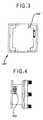
- Fig. 3, Fig. 4, and Fig 5 show a bottom view, a side view, and a top plan view of a multipole multiposition microwave switch system 101 respectively.
- Fig. 3 and Fig 4 show a standard "D" shape connector 103 , protruding out of a housing 105 of the multipole multiposition microwave switch system 101 .
- the standard "D" shape connector 103 carries the control commands to control the switching of plurality of switches within the multipole multiposition microwave switch system 101 .
- FIG. 3, Fig. 4 and Fig. 5 illustrate the outward appearance of a 4P5T embodiment of the multipole multiposition microwave switch system 101 .
- This embodiment comprises of a first RF input connector 107 and a first RF output connector 109 , a second RF input connector 111 and a second RF output connector 113 , a third RF input connector 115 and a third RF output connector 117 , a fourth RF input connector 119 and a fourth RF output connector 121 , and a redundant RF input connector 123 .
- Fig. 6 is a schematic of the multipole multiposition microwave switch system 101 of 4P5T. This schematic illustrates the simplicity of the multipole multiposition microwave switch system 101 .
- the first RF input connector 107 is connected to a first RF switch 125
- the second RF input connector 111 is connected to a second RF switch 127
- the third RF input connector 115 is connected to a third RF switch 129
- the fourth RF input connector 119 is connected to a fourth RF switch 131
- the first RF output connector 109 is connected to a first interface blade 133
- the second RF output connector 113 is connected to a second interface blade 135
- the third RF output connector 117 is connected to a third interface blade 137
- the fourth RF output connector 121 is connected to a fourth interface blade 139 .
- the redundant RF input connector 123 is commonly and parallelly connected to a first control switch 141 , a second control switch 143 , a third control switch 145 , and a fourth control switch 147 . Because the redundant RF input connector 123 is commonly and parallelly connected to the first control switch 141 , the second control switch 143 , the third control switch 145 , and the fourth control switch 147 , one can observe that a single external connection point provided by the redundant RF input connector 123 can give a redundant electrical path to each of the first control switch 141 , the second control switch 143 , the third control switch 145 , and the fourth control switch 147 .
- each of the electrical input carried by the RF input connectors 107 , 111 , 115 , and 119 can now be transmitted to the corresponding RF output connectors 109 , 113 , 117 , and 121 by a single redundant RF input connector 123 .
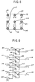
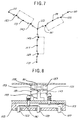
- Fig. 7 is a simplified line schematic of another version of the multipole multiposition microwave switch system 101 , a 3P4T system. Although the first interface blade 133 , the second interface blade 135 , and the third interface blade 137 are not shown for the simplicity of the schematic, the simplest form of the present invention is fully illustrated. From Fig. 7, one can observe that the redundant RF input connector 123 is commonly and serially connected to each of three control switches 141 , 143 , 145 .
- Fig. 8 is a simplified cross-sectional view of the means for commanding each of the RF switches 125 , 127 , 129 , and 131 , and each of the control switches 141 , 143 , 145 , and 147 by the use of corresponding interface blades 133 , 135 , 137 , and 139 .
- the first RF input connector 107 , the first output connector 109 , and the redundant RF input connector 123 are protruding out of the housing 105 .
- the first control switch 141 has two ends wherein one end can make an electrical contact with the redundant RF input connector 123 and the other end can make an electrical contact with the first RF output connector 109 .
- the first control switch 141 is made of electrically conductive material so that when two ends of the first control switch 141 are making electrical contact with the redundant RF input connector 123 and the first RF output connector 109 , an electrical circuit between the redundant RF input connector 123 and the first RF output connector 109 is complete.
- the first RF switch 125 has two ends wherein one end can make an electrical contact with the first RF input connector 107 and the other end can make an electrical contact with the first RF output connector 109 .
- the first RF switch 125 is made of electrically conductive material so that when two ends of the first RF switch 125 are making electrical contact with the first RF input connector 107 and the first RF output connector 109 , an electrical circuit between the first RF input connector 107 and the first RF output connector 109 is complete.
- the first interface blade 133 is positioned between the first control switch 141 and the first RF switch 125 .
- the first interface blade 133 has a first end of the first interface blade 149 , a second end of the first interface blade 151 , and a middle portion of the first interface blade 153 .
- the first end of the first interface blade 149 is attached to an extension from the first RF switch 125
- the second end of the first interface blade 151 is attached to an extension from the first control switch 141
- a middle portion of the first interface blade 153 is pivotally hinged on a first interface blade support 155 which is securely attached to the housing 105 .
- first solenoid 157 for the first end of the first interface blade 149
- second solenoid 159 for the second end of the first interface blade 151
- permanent magnet 161 for the first interface blade 133 .
- An operator can control the toggling of the first end of the first interface blade 149 and the second end of the first interface blade 151 by selectively sending the current to either the first solenoid 157 for the first end of the first interface blade 159 , or the second solenoid 159 for the second end of the first interface blade 159 .
- the middle portion of the first interface blade 153 is rotably pivoted on the first interface blade support 155 , the first interface blade 133 will seesaw back and forth, enabling the switching on and off of both the first RF switch 125 and the first control switch 141 .
- Fig. 9 is a simplified line schematic of the multipole multiposition microwave switch system 101 of 4P5T which is illustrated in Fig. 3, Fig. 4, Fig. 5, and Fig. 6. Similar to Fig. 7, the first interface blade 133 , the second interface blade 135 , the third interface blade 137 , and the fourth interface blade 139 are not shown for the simplicity of the schematic. From Fig. 9, one can once again observe that the redundant RF input connector 123 is commonly and serially connected to each of four control switches 141 , 143 , 145 , 147 .
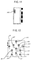
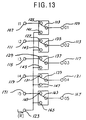
- Fig. 10 is a simplified line schematic of the multipole multiposition microwave switch system 101 of 5P6T. Similar to Fig. 7 and Fig. 9, the first interface blade 133 , the second interface blade 135 , the third interface blade 137 , the fourth interface blade 139 , and a fifth interface blade 163 (shown in Fig. 13) are not shown for the simplicity of the schematic. From Fig. 10, one can once again observe that the redundant RF input connector 123 is commonly and serially connected to each of four control switches 141 , 143 , 145 , 147 , and with a fifth control switch 165 . The fifth control switch 165 connects between the redundant RF input connector 123 and a fifth RF output connector 167 . Also, a fifth RF switch 169 connects between the fifth RF output connector 167 and a fifth RF input connector 171 .
- Fig. 11, and Fig. 12 show a side view, and a top plan view of the multipole multiposition microwave switch system 101 of 5P6T respectively.
- Fig. 11, and Fig. 12 also show the standard "D" shape connector 103 , protruding out of a housing 105 of the multipole multiposition microwave switch system 101 .
- the standard "D" shape connector 103 carries the control commands to control the switching of plurality of switches within the multipole multiposition microwave switch system 101 .
- the embodiment of 5P6T comprises of the first RF input connector 107 and the first RF output connector 109 , the second RF input connector 111 and the second RF output connector 113 , the third RF input connector 115 and the third RF output connector 117 , the fourth RF input connector 119 and the fourth RF output connector 121 , the fifth RF input connector 171 and the fifth RF output connector 167 , and the redundant RF input connector 123 .
- Fig. 13 is a schematic of the multipole multiposition microwave switch system 101 of 5P6T. In addition to the elements shown in Fig. 6, Fig. 13 also shows the fifth interface blade 163 , the fifth control switch 165 , the fifth RF output connector 167 , fifth RF switch 169 , and the fifth RF input connector 171 .
- Fig. 14 is a simplified line schematic of the multipole multiposition microwave switch system 101 of 6P7T. Similar to Fig. 7, Fig. 9, and Fig. 10, the first interface blade 133 , the second interface blade 135 , the third interface blade 137 , the fourth interface blade 139 , the fifth interface blade 163 , a sixth interface blade are not shown for the simplicity of the schematic.
- the redundant RF input connector 123 is commonly and serially connected to each of five control switches 141 , 143 , 145 , 147 , 165 and with a sixth control switch 173 .
- the sixth control switch 173 connects between the redundant RF input connector 123 and a sixth RF output connector 175 .
- a sixth RF switch 177 connects between the sixth RF output connector 175 and a sixth RF input connector 179 .
- this invention allows the packaging of any variety of multiple-pole-(multiple plus one)-throw [(N)P(N+1)T] multipole multiposition microwave switch system; such as 3P4T, 4P5T, 5P6T, 6P7T, 7T8P, and others with more switches.
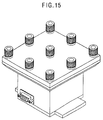
- Fig. 15 is an isometric view of the multipole multiposition microwave switch system 101 of 4P5T. The simplicity of the design is apparent.
- Fig. 1 shows an example of such a combination which has a group of four individual SPDT's connected to one SP4T switch.
- One difficulty with such a combination of a multiple SPDT's with a SPMT is that as the number of SPDT's increased, the number of external connections increased dramatically. And as the number of connection increased outside the metal housing, and as the frequency of the signal being carried by the system climbed higher, it has been increasingly difficult to maintain optimized impedance match to the active channel. Therefore, it is also difficult to obtain low interference among the signals and low voltage standing wave ratio. Additionally, it has been increasingly difficult to maintain adequate RF voltage and RF power handling capabilities while still maintaining good isolation for the unused channels.
- this invention does not require any external connections to form a [(N)P(N+1)T]. Therefore, it is easier to maintain the optimized impedance match to the active channel, and easier to obtain low interference among the signals. Additionally, because the number of connectors required is reduced, the voltage loss is also minimized; increasing the RF power handling efficiency.
- this invention allows the packaging of any variety of multiple-pole-(multiple plus one)-throw [(N)P(N+1)T] multipole multiposition microwave switch system; such as 3P4T, 4P5T, 5P6T, 6P7T, 7T8P, and others with more switches.
- One additional advantage is the simplicity of the invention. Many of the SPDT's can now be combined within one packaging because of this invention. This feature is especially important when the system requires high frequency of switching as the simplicity of the design and the single redundant connection shared among many channels reduce the probability of the system failure. Moreover, because there is not a need for wiring between switches, the present invention requires less operator's valuable time.
- the multipole multiposition microwave switch system 101 can have a different means of switching each of the control switches and the RF switches without using the interface blades.
- Such a different mean may be a use of a group of solenoids to differently activating each of the control switches and the RF switches.
Landscapes
- Waveguide Switches, Polarizers, And Phase Shifters (AREA)
- Transmitters (AREA)
- Transceivers (AREA)
- Radio Relay Systems (AREA)
- Electronic Switches (AREA)
Applications Claiming Priority (2)
| Application Number | Priority Date | Filing Date | Title |
|---|---|---|---|
| US694600 | 1996-08-09 | ||
| US08/694,600 US5712603A (en) | 1996-08-09 | 1996-08-09 | Multipole multiposition microwave switch with a common redundancy |
Publications (2)
| Publication Number | Publication Date |
|---|---|
| EP0823745A2 true EP0823745A2 (de) | 1998-02-11 |
| EP0823745A3 EP0823745A3 (de) | 1999-06-16 |
Family
ID=24789512
Family Applications (1)
| Application Number | Title | Priority Date | Filing Date |
|---|---|---|---|
| EP97113766A Withdrawn EP0823745A3 (de) | 1996-08-09 | 1997-08-08 | Mehrpoliger Mehrstellungs-Mikrowellenschalter mit gemeinsamer Redundanz |
Country Status (5)
| Country | Link |
|---|---|
| US (1) | US5712603A (de) |
| EP (1) | EP0823745A3 (de) |
| JP (1) | JP3288270B2 (de) |
| KR (1) | KR100233234B1 (de) |
| CN (1) | CN1119823C (de) |
Cited By (1)
| Publication number | Priority date | Publication date | Assignee | Title |
|---|---|---|---|---|
| AT408915B (de) * | 1999-01-19 | 2002-04-25 | Vaillant Gmbh | Heizungsanlage |
Families Citing this family (12)
| Publication number | Priority date | Publication date | Assignee | Title |
|---|---|---|---|---|
| US5828268A (en) * | 1997-06-05 | 1998-10-27 | Hughes Electronics Corporation | Microwave switches and redundant switching systems |
| US6006112A (en) * | 1997-11-26 | 1999-12-21 | Lucent Technologies, Inc. | Transceiver with RF loopback and downlink frequency scanning |
| US6133812A (en) * | 1998-05-21 | 2000-10-17 | Relcomm Technologies, Inc. | Switching relay with magnetically resettable actuator mechanism |
| US6545562B2 (en) * | 2001-02-09 | 2003-04-08 | Adc Telecommunications, Inc. | Plug connector for cable television network and method of use |
| WO2006075307A2 (en) * | 2005-01-17 | 2006-07-20 | Nxp B.V. | Modular switching arrangement |
| KR100686962B1 (ko) | 2005-12-19 | 2007-02-26 | 주식회사 에이스테크놀로지 | 리던던시 스위치 장치 |
| KR100718000B1 (ko) * | 2005-12-30 | 2007-05-15 | 고려대학교 산학협력단 | 멀티레이어 구조의 쌍방향 스위치 및 이를 구비한 기지국장치 |
| JP2007251587A (ja) * | 2006-03-16 | 2007-09-27 | Agilent Technol Inc | スイッチマトリクス |
| US7511593B2 (en) * | 2006-08-14 | 2009-03-31 | Eacceleration Corporation | DVI-compatible multi-pole double-throw mechanical switch |
| US8188809B2 (en) * | 2008-12-02 | 2012-05-29 | Nokia Corporation | Output selection of multi-output filter |
| US8196684B2 (en) * | 2010-10-20 | 2012-06-12 | Caiozza Joseph C | Wearable folding wing apparatus |
| CN104021955A (zh) * | 2014-05-20 | 2014-09-03 | 北京雷格讯电子有限责任公司 | 恒定接触力运动技术 |
Family Cites Families (32)
| Publication number | Priority date | Publication date | Assignee | Title |
|---|---|---|---|---|
| US3739306A (en) * | 1970-09-03 | 1973-06-12 | Bunker Ramo | Microwave coaxial switch |
| AT314020B (de) * | 1971-04-13 | 1974-02-15 | Bunker Ramo | Elektrischer schalter |
| US3764939A (en) * | 1972-06-12 | 1973-10-09 | Gen Electric | Rf matching system for high frequency relays |
| US3808566A (en) * | 1973-05-24 | 1974-04-30 | Gen Dynamics Corp | Switching system |
| US4206332A (en) * | 1977-05-09 | 1980-06-03 | Tektronix, Inc. | Coaxial switch |
| US4198611A (en) * | 1977-08-01 | 1980-04-15 | Rca Corporation | Redundancy system with eight devices for five channels |
| US4187416A (en) * | 1977-09-21 | 1980-02-05 | The United States Of America As Represented By The Administrator Of The National Aeronautics And Space Administration | High power RF coaxial switch |
| DE2753420C3 (de) * | 1977-11-30 | 1980-06-19 | Siemens Ag, 1000 Berlin Und 8000 Muenchen | Einrichtung zur Ersatzschaltung von Betriebssystemen für digitale Signale |
| US4167714A (en) * | 1978-03-20 | 1979-09-11 | Burroughs Corporation | Constant impedance transmission line routing network |
| JPS5844829A (ja) * | 1981-09-11 | 1983-03-15 | Nippon Telegr & Teleph Corp <Ntt> | 衛星搭載装置の冗長装置 |
| US4399439A (en) * | 1981-11-23 | 1983-08-16 | Rca Corporation | Signal switching matrix |
| US4502027A (en) * | 1982-03-01 | 1985-02-26 | Raytheon Company | Bidirectional switch |
| US4477781A (en) * | 1983-02-17 | 1984-10-16 | The United States Of America As Represented By The Secretary Of The Navy | Combined microwave parallel amplifier- RF attenuator/modulator |
| US4583061A (en) * | 1984-06-01 | 1986-04-15 | Raytheon Company | Radio frequency power divider/combiner networks |
| JPS61112401A (ja) * | 1984-07-20 | 1986-05-30 | Nec Corp | 超高周波スイツチ |
| US4697056A (en) * | 1984-08-02 | 1987-09-29 | Dynatech/U-Z, Inc. | Multiposition microwave switch with extended operational frequency range |
| US4736171A (en) * | 1986-01-15 | 1988-04-05 | The United States Of America As Represented By The Secretary Of The Air Force | Adaptive microwave channelization |
| US4695811A (en) * | 1986-07-28 | 1987-09-22 | Tektronix, Inc. | High frequency coaxial switch |
| US4795960A (en) * | 1986-12-02 | 1989-01-03 | Bruce Malcolm | Programmable attenuators |
| US4779065A (en) * | 1987-04-28 | 1988-10-18 | General Electric Company | Microwave signal routing matrix |
| US4755769A (en) * | 1987-05-20 | 1988-07-05 | General Electric Company | Composite amplifier with efficient power reduction |
| JPS63318839A (ja) * | 1987-06-22 | 1988-12-27 | Nippon Telegr & Teleph Corp <Ntt> | 切替機能内蔵端局装置 |
| US4924196A (en) * | 1988-12-14 | 1990-05-08 | Hughes Aircraft Company | Waveguide matrix switch |
| US4965542A (en) * | 1989-02-28 | 1990-10-23 | Victor Nelson | Magnetic switch for coaxial transmission lines |
| US4982442A (en) * | 1989-04-25 | 1991-01-01 | Motorola, Inc. | Low cost antenna switch using relays configured in a transmit/receive arrangement |
| CA2014585C (en) * | 1990-04-12 | 1992-11-03 | R. Glenn Thomson | C-, s- and t-switches operated by permanent magnets |
| US5132644A (en) * | 1990-06-13 | 1992-07-21 | Knorr Siegfried G | Microwave cavity switch |
| EP0577888A1 (de) * | 1992-05-29 | 1994-01-12 | Nec Corporation | Schaltungsanordnung für redundantes Signalübertragungssystem |
| US5281936A (en) * | 1992-06-01 | 1994-01-25 | Teledyne Industries, Inc. | Microwave switch |
| JPH0786988A (ja) * | 1993-09-16 | 1995-03-31 | Fujitsu Ltd | Pca伝送装置及びpca伝送方法 |
| US5451918A (en) * | 1994-05-04 | 1995-09-19 | Teledyne Industries, Inc. | Microwave multi-port transfer switch |
| US5481073A (en) * | 1994-06-09 | 1996-01-02 | Quintech, Inc. | Modular broadband bidirectional programmable switch system with stacked modular switch arrangement |
-
1996
- 1996-08-09 US US08/694,600 patent/US5712603A/en not_active Expired - Fee Related
-
1997
- 1997-08-08 EP EP97113766A patent/EP0823745A3/de not_active Withdrawn
- 1997-08-09 KR KR1019970038114A patent/KR100233234B1/ko not_active Expired - Fee Related
- 1997-08-09 CN CN97118556A patent/CN1119823C/zh not_active Expired - Fee Related
- 1997-08-11 JP JP21653597A patent/JP3288270B2/ja not_active Expired - Fee Related
Cited By (1)
| Publication number | Priority date | Publication date | Assignee | Title |
|---|---|---|---|---|
| AT408915B (de) * | 1999-01-19 | 2002-04-25 | Vaillant Gmbh | Heizungsanlage |
Also Published As
| Publication number | Publication date |
|---|---|
| KR100233234B1 (ko) | 1999-12-01 |
| EP0823745A3 (de) | 1999-06-16 |
| US5712603A (en) | 1998-01-27 |
| KR19980018554A (ko) | 1998-06-05 |
| JP3288270B2 (ja) | 2002-06-04 |
| CN1119823C (zh) | 2003-08-27 |
| CN1175785A (zh) | 1998-03-11 |
| JPH10224103A (ja) | 1998-08-21 |
Similar Documents
| Publication | Publication Date | Title |
|---|---|---|
| US5712603A (en) | Multipole multiposition microwave switch with a common redundancy | |
| US4375622A (en) | Multiport radio frequency signal combiner | |
| US6958665B2 (en) | Micro electro-mechanical system (MEMS) phase shifter | |
| US5270719A (en) | Transmission/reception module for an electronically phase-controlled antenna | |
| US9059495B2 (en) | Compact multiport waveguide switches | |
| US5451918A (en) | Microwave multi-port transfer switch | |
| US7046101B2 (en) | Switchable RF power divider/combiner with switchable impedance matching elements | |
| US4061989A (en) | Redundancy switching system | |
| CN110739509A (zh) | 一种高频微波传输系统及单刀十掷同轴开关 | |
| EP2940782B1 (de) | Halbleiterdiodenschalter | |
| US4361905A (en) | Arrangement for connecting selected antennas to a radio for transmitting and receiving | |
| US6816026B2 (en) | Orthogonal polarization and frequency selectable waveguide using rotatable waveguide sections | |
| US5270505A (en) | Remote controlled switch/receptacle | |
| CN109088132A (zh) | 一种通信卫星多波束切换的多结铁氧体开关网络 | |
| US10498415B2 (en) | Systems and methods for a multi-mode active electronically scanned array | |
| US4151489A (en) | Waveguide switch having four ports and three connecting states | |
| KR100354706B1 (ko) | 합성 채널수에 따른 임피던스 정합 선로를 갖는 n경로 | |
| US6118911A (en) | Waveguide switch matrix using junctions matched in only one state | |
| Figur et al. | Design and characterization of a simplified planar 16× 8 RF MEMS switch matrix for a GEO-stationary data relay | |
| WO1998039812A8 (en) | A high frequency multi-port switching circuit | |
| KR102869897B1 (ko) | 밀리미터 파 범위 용 다기능 정류기 | |
| KR20040025424A (ko) | 임피던스 정합 합성 및 분배기 | |
| US6525650B1 (en) | Electronic switching matrix | |
| US20060001510A1 (en) | High isolation rf switch | |
| EP0308859A2 (de) | Hohlleiterschalter mit Dielektrikum gefüllten Hohlleitern |
Legal Events
| Date | Code | Title | Description |
|---|---|---|---|
| PUAI | Public reference made under article 153(3) epc to a published international application that has entered the european phase |
Free format text: ORIGINAL CODE: 0009012 |
|
| AK | Designated contracting states |
Kind code of ref document: A2 Designated state(s): AT BE CH DE DK ES FI FR GB GR IE IT LI LU MC NL PT SE |
|
| PUAL | Search report despatched |
Free format text: ORIGINAL CODE: 0009013 |
|
| AK | Designated contracting states |
Kind code of ref document: A3 Designated state(s): AT BE CH DE DK ES FI FR GB GR IE IT LI LU MC NL PT SE |
|
| AKX | Designation fees paid | ||
| REG | Reference to a national code |
Ref country code: DE Ref legal event code: 8566 |
|
| STAA | Information on the status of an ep patent application or granted ep patent |
Free format text: STATUS: THE APPLICATION IS DEEMED TO BE WITHDRAWN |
|
| 18D | Application deemed to be withdrawn |
Effective date: 19991217 |