EP0308859A2 - Hohlleiterschalter mit Dielektrikum gefüllten Hohlleitern - Google Patents
Hohlleiterschalter mit Dielektrikum gefüllten Hohlleitern Download PDFInfo
- Publication number
- EP0308859A2 EP0308859A2 EP88115376A EP88115376A EP0308859A2 EP 0308859 A2 EP0308859 A2 EP 0308859A2 EP 88115376 A EP88115376 A EP 88115376A EP 88115376 A EP88115376 A EP 88115376A EP 0308859 A2 EP0308859 A2 EP 0308859A2
- Authority
- EP
- European Patent Office
- Prior art keywords
- dielectrically loaded
- switch
- waveguide
- loaded waveguide
- dielectrically
- Prior art date
- Legal status (The legal status is an assumption and is not a legal conclusion. Google has not performed a legal analysis and makes no representation as to the accuracy of the status listed.)
- Granted
Links
Images
Classifications
-
- H—ELECTRICITY
- H01—ELECTRIC ELEMENTS
- H01P—WAVEGUIDES; RESONATORS, LINES, OR OTHER DEVICES OF THE WAVEGUIDE TYPE
- H01P1/00—Auxiliary devices
- H01P1/10—Auxiliary devices for switching or interrupting
- H01P1/12—Auxiliary devices for switching or interrupting by mechanical chopper
- H01P1/122—Waveguide switches
Definitions
- the present invention relates to microwave circuits. More specifically, the present invention relates to switches used to connect signals from two or more microwave channels.
- Microwave switches selectively connect channels in microwave circuits and systems.
- the two categories of switches related to this invention are coaxial switches and waveguide switches.
- Coaxial switches are known to have several limitations. The most severe being power handling capability. The maximum average power that the coaxial switch can handle is typically limited by overheating of the internal switch materials due to RF losses. The conventional designs typically result in poor thermal conductivity from the transmission line center conductor. Poor thermal conductivity results in excessive heat build-up which can cause the safe operating temperatures of the materials being used to be exceeded resulting in failures.
- Multipacting breakdown is a resonant radio frequency discharge which is attributable to secondary emissions of electrons from discharging surfaces when a radio frequency field of sufficient magnitude and proper frequency is applied across a gap in a vacuum. Multipacting causes disruption of communications and if not controlled can lead to destruction of the switch.
- Coaxial switches are also generally more mechanically complex than other designs. As a result, many switch configurations, though realizable, are difficult and costly to implement in a coaxial design.
- Waveguide switches do not have the mechanical complexity or the power limitations of the coaxial switches. However, these switches are generally much larger and heavier than coax switches for C band and lower frequencies. Thus, current waveguide switches are generally not acceptable for use in many spacecraft applications.
- the dielectrically loaded waveguide switch of the present invention provides a high power handling switch with small size and low weight.
- the dielectrically loaded waveguide switch of the present invention includes first and second dielectrically loaded waveguides selectively connected by a switch.
- the switch includes a third dielectrically loaded waveguide mounted for communication with said first and second waveguides upon switch actuation.
- Fig. 1 shows a typical conventional switch 10′
- the switch 10′ is partially in section and includes a rotor 12′ which contains a plurality of waveguides 16′ 20′ and 24, and a stator 14, which contains a plurality of waveguides 15′, 18′, 22′ and 26′.
- the rotor 12′ and stator 14′ are typically made of aluminum or other suitable material.
- the waveguides 15′, 16′, 18′, 20′, 22′, 24′, and 26′ are typically rectangular, square or circular housings each of which is sized to propagate at a particular frequency.
- the rotor 12′ is rotated to align the desired waveguides for transmission of a microwave signal between the appropriate waveguide ports 28′ 30′ 32, and 34′.
- a microwave signal supplied to waveguide port 28′ will propagate through waveguides 15′ 16′ and 22′ to waveguide port 30′and a microwave signal supplied to waveguide port 32′will propagate through waveguides 18′ 20′ and 26′to waveguide port 34′.
- the number and configuration of the waveguides 15′ 16′, 18′, 20′, 22′, 24′ and 26′ may vary without departing from the scope of the present invention.
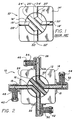
- Fig. 2 shows a corresponding illustrative embodiment of dielectrically loaded waveguide switch 10 utilizing the teachings of the present invention.
- the switch 10 is shown in section and includes a rotor 12 which contains a plurality of dielectrically loaded waveguides 16, 20 and 24 and a stator 14 which contains a plurality of dielectrically loaded waveguides 15, 18, 22, and 26.
- the dielectrically loaded waveguides 15, 16, 18, 20, 22, 24, and 26 differ from waveguides 15′ 16′, 18′, 20′, 22′, 24′ and 26′ of the related art in that waveguides 15, 16, 18, 20, 22, 24 and 26 are loaded with a dielectric material
- dielectrically loaded waveguides 15, 22, 18 and 26 of the present invention differ from waveguides 15′ 22′, 18′ and 26′ of the related art in that dielectrically loaded waveguides 15, 22, 18 and 26 are coupled to coaxial connectors 40, 42, 44, and 46 respectively through coaxial probes 48, 50, 52, and 54 respectively.
- dielectrically loaded waveguides 15, 16, 18, 20, 22, 24 and 26 is reduced from the size of waveguides 15′, 16′, 18′, 20′, 22′, 24′ and 26′ of the related art by the square root of the dielectric constant (e r ) of the loading material.
- a common low loss dielectric material fabricated from Barium tetritinate has an e r of 37.
- the dielectrically loaded waveguides 15, 16, 18, 20, 22, 24 and 26 of the present invention can be reduced in size to less than one sixth that of waveguides 15′, 16′, 18′, 20′, 22′, 24′ and 26′ of the related art.
- the invention is not limited to any particular size of waveguide or type of dielectric material. Those skilled in the art having access to the present teachings will be able to design dielectrically loaded waveguide switches using dielectric materials suitable for the switch size, and microwave frequency desired for a particular application.
- the rotor 12 is essentially the same as 12′ of the related art except that the size of the rotor 12 can be substantially reduced due to the reduced size of waveguides 16, 20 and 24.
- the stator 14 is essentially the same as 14′ of the related art with the exception that coaxial connectors 40, 42, 44 and 46 are mounted on stator 14 and the size of stator 14 is reduced due to the reduced size of dielectrically loaded waveguides 15, 18, 22 and 26.
- connectors 40, 42, 44, and 46 may be SMA or other suitable connectors without departing from the scope of the present invention.
- transitions to dielectrically loaded waveguides or to standard waveguides could be used in place of a coaxial connector without departing from the scope of the present invention.
- a microwave signal supplied to coaxial connector 40 will propagate along coaxial probe 48 and through dielectrically loaded waveguides 15, 16 and 22 to coaxial probe 50 of coaxial connector 42 and a microwave signal supplied to coaxial connector 44 will propagate along coaxial probe 52 and through dielectrically loaded waveguides 18, 20, and 26 to coaxial probe 54 of coaxial connector 46.
- a microwave signal supplied to coaxial connector 44 will propagate along coaxial probe 52 and through dielectrically loaded waveguides 18, 20, and 26 to coaxial probe 54 of coaxial connector 46.
- the present invention is not limited to switches. Instead it may be used wherever it is desired to reduce the size of a waveguide.
- the present invention allows for a variety of system configurations by which waveguides are switched.
Landscapes
- Waveguide Switches, Polarizers, And Phase Shifters (AREA)
Applications Claiming Priority (2)
| Application Number | Priority Date | Filing Date | Title |
|---|---|---|---|
| US07/099,401 US4908589A (en) | 1987-09-21 | 1987-09-21 | Dielectrically loaded waveguide switch |
| US99401 | 1987-09-21 |
Publications (3)
| Publication Number | Publication Date |
|---|---|
| EP0308859A2 true EP0308859A2 (de) | 1989-03-29 |
| EP0308859A3 EP0308859A3 (en) | 1990-04-25 |
| EP0308859B1 EP0308859B1 (de) | 1994-06-15 |
Family
ID=22274836
Family Applications (1)
| Application Number | Title | Priority Date | Filing Date |
|---|---|---|---|
| EP88115376A Expired - Lifetime EP0308859B1 (de) | 1987-09-21 | 1988-09-20 | Hohlleiterschalter mit Dielektrikum gefüllten Hohlleitern |
Country Status (5)
| Country | Link |
|---|---|
| US (1) | US4908589A (de) |
| EP (1) | EP0308859B1 (de) |
| JP (1) | JPH01164101A (de) |
| CA (1) | CA1294015C (de) |
| DE (1) | DE3850200T2 (de) |
Families Citing this family (4)
| Publication number | Priority date | Publication date | Assignee | Title |
|---|---|---|---|---|
| DE19856334A1 (de) * | 1998-12-07 | 2000-06-08 | Bosch Gmbh Robert | Hohlleiterschalter |
| US10522888B2 (en) | 2015-08-03 | 2019-12-31 | European Space Agency | Microwave branching switch |
| US20180275760A1 (en) | 2017-03-23 | 2018-09-27 | Mindmaze Holding Sa | System, method and apparatus for accurately measuring haptic forces |
| US11205825B2 (en) | 2018-03-23 | 2021-12-21 | Victor Nelson | Non-contact type coaxial switch |
Family Cites Families (15)
| Publication number | Priority date | Publication date | Assignee | Title |
|---|---|---|---|---|
| US2427940A (en) * | 1943-01-28 | 1947-09-23 | Rca Corp | Transmission line switch |
| US2413298A (en) * | 1943-07-01 | 1946-12-31 | Gen Electric | Ultra high frequency switch |
| US2761137A (en) * | 1946-01-05 | 1956-08-28 | Lester C Van Atta | Solid dielectric waveguide with metal plating |
| US2759153A (en) * | 1950-06-22 | 1956-08-14 | Gen Comm Company | Radio frequency electric switch |
| US2766355A (en) * | 1953-08-25 | 1956-10-09 | Thompson Prod Inc | Coaxial switch |
| US2822524A (en) * | 1954-10-25 | 1958-02-04 | Sanders Associates Inc | Wave guide |
| US2816198A (en) * | 1954-11-05 | 1957-12-10 | Thompson Prod Inc | Coaxial switch |
| US3001053A (en) * | 1957-06-20 | 1961-09-19 | Alford Andrew | Coaxial switch |
| US3346825A (en) * | 1965-06-28 | 1967-10-10 | Ass Elect Ind | Waveguide switch with semiconductor in thermal contact with waveguide walls |
| US3577105A (en) * | 1969-05-29 | 1971-05-04 | Us Army | Method and apparatus for joining plated dielectric-form waveguide components |
| JPS5444113B2 (de) * | 1973-08-20 | 1979-12-24 | ||
| US4242652A (en) * | 1978-07-10 | 1980-12-30 | Hughes Aircraft Company | Four port waveguide switch |
| FR2535547B1 (fr) * | 1982-10-29 | 1988-09-16 | Thomson Csf | Resonateurs bi-rubans et filtres realises a partir de ces resonateurs |
| US4490700A (en) * | 1982-12-01 | 1984-12-25 | The United States Of America As Represented By The Secretary Of The Army | Dielectric waveguide ferrite modulator/switch |
| EP0293386B1 (de) * | 1986-02-18 | 1992-05-13 | TELDIX GmbH | Mikrowellenschalter mit wenigstens zwei schaltstellungen |
-
1987
- 1987-09-21 US US07/099,401 patent/US4908589A/en not_active Expired - Fee Related
-
1988
- 1988-09-20 EP EP88115376A patent/EP0308859B1/de not_active Expired - Lifetime
- 1988-09-20 CA CA000577854A patent/CA1294015C/en not_active Expired - Fee Related
- 1988-09-20 DE DE3850200T patent/DE3850200T2/de not_active Expired - Fee Related
- 1988-09-21 JP JP63235129A patent/JPH01164101A/ja active Pending
Also Published As
| Publication number | Publication date |
|---|---|
| EP0308859A3 (en) | 1990-04-25 |
| DE3850200D1 (de) | 1994-07-21 |
| DE3850200T2 (de) | 1994-12-15 |
| JPH01164101A (ja) | 1989-06-28 |
| CA1294015C (en) | 1992-01-07 |
| EP0308859B1 (de) | 1994-06-15 |
| US4908589A (en) | 1990-03-13 |
Similar Documents
| Publication | Publication Date | Title |
|---|---|---|
| Fromm et al. | A new microwave rotary joint | |
| US9979067B2 (en) | N-way, ridged waveguide, radial power combiner/divider | |
| US4754239A (en) | Waveguide to stripline transition assembly | |
| EP0455485B1 (de) | Raumfeldleistungsaddierer | |
| US4491810A (en) | Multi-port, multi-frequency microwave combiner with overmoded square waveguide section | |
| CA1192629A (en) | Dual polarization transition and/or switch | |
| EP0556941B1 (de) | Antenne und Mikrowellenumsetzer, in einer Schaltungspackung integriert | |
| US4686498A (en) | Coaxial connector | |
| KR100233234B1 (ko) | 공통 리던던시를 갖는 다극 다위치 마이크로웨이브 스위치 | |
| US4908589A (en) | Dielectrically loaded waveguide switch | |
| US10177726B1 (en) | Waveguide to microstrip line N-port power splitter/combiner | |
| Kazemi et al. | Radial power combiners—An overview: A comprehensive analysis of power combiners, their structures and evolution from their inception to the present | |
| US20190348732A1 (en) | Non-contact type coaxial switch | |
| US11205825B2 (en) | Non-contact type coaxial switch | |
| US4117426A (en) | Multiple channel rotary joint | |
| US4473807A (en) | Coaxial K inverter | |
| US3199055A (en) | Microwave rotary joint | |
| US9705171B2 (en) | Dielectric resonator filter and multiplexer having a common wall with a centrally located coupling iris and a larger peripheral aperture adjustable by a tuning screw | |
| Jia et al. | Analysis of a passive spatial combiner using tapered slotline array in oversized coaxial waveguide | |
| US5212462A (en) | Stripline microwave module having means for contactless coupling between signal lines on different planar levels | |
| US3281728A (en) | Rotating joint assembly | |
| US3886499A (en) | High frequency electrical network with frequency dependent characteristics having a constant input resistance | |
| EP0343887A1 (de) | Wellenleitervorrichtung | |
| GB2218854A (en) | Waveguide apparatus | |
| US3188588A (en) | Te01 mode coaxial waveguide system and rotary joint |
Legal Events
| Date | Code | Title | Description |
|---|---|---|---|
| PUAI | Public reference made under article 153(3) epc to a published international application that has entered the european phase |
Free format text: ORIGINAL CODE: 0009012 |
|
| 17P | Request for examination filed |
Effective date: 19881011 |
|
| AK | Designated contracting states |
Kind code of ref document: A2 Designated state(s): DE FR GB IT |
|
| PUAL | Search report despatched |
Free format text: ORIGINAL CODE: 0009013 |
|
| AK | Designated contracting states |
Kind code of ref document: A3 Designated state(s): DE FR GB IT |
|
| 17Q | First examination report despatched |
Effective date: 19921216 |
|
| GRAA | (expected) grant |
Free format text: ORIGINAL CODE: 0009210 |
|
| AK | Designated contracting states |
Kind code of ref document: B1 Designated state(s): DE FR GB IT |
|
| REF | Corresponds to: |
Ref document number: 3850200 Country of ref document: DE Date of ref document: 19940721 |
|
| PGFP | Annual fee paid to national office [announced via postgrant information from national office to epo] |
Ref country code: FR Payment date: 19940808 Year of fee payment: 7 |
|
| ITF | It: translation for a ep patent filed | ||
| PGFP | Annual fee paid to national office [announced via postgrant information from national office to epo] |
Ref country code: GB Payment date: 19940815 Year of fee payment: 7 |
|
| PGFP | Annual fee paid to national office [announced via postgrant information from national office to epo] |
Ref country code: DE Payment date: 19940824 Year of fee payment: 7 |
|
| ET | Fr: translation filed | ||
| PLBE | No opposition filed within time limit |
Free format text: ORIGINAL CODE: 0009261 |
|
| STAA | Information on the status of an ep patent application or granted ep patent |
Free format text: STATUS: NO OPPOSITION FILED WITHIN TIME LIMIT |
|
| 26N | No opposition filed | ||
| PG25 | Lapsed in a contracting state [announced via postgrant information from national office to epo] |
Ref country code: GB Effective date: 19950920 |
|
| GBPC | Gb: european patent ceased through non-payment of renewal fee |
Effective date: 19950920 |
|
| PG25 | Lapsed in a contracting state [announced via postgrant information from national office to epo] |
Ref country code: FR Effective date: 19960531 |
|
| PG25 | Lapsed in a contracting state [announced via postgrant information from national office to epo] |
Ref country code: DE Effective date: 19960601 |
|
| REG | Reference to a national code |
Ref country code: FR Ref legal event code: ST |
|
| PG25 | Lapsed in a contracting state [announced via postgrant information from national office to epo] |
Ref country code: IT Free format text: LAPSE BECAUSE OF NON-PAYMENT OF DUE FEES Effective date: 20050920 |