EP0823581B1 - Aluminiumfolienstruktur und Verfahren zum Erzeugen einer Aluminiumfolienstruktur - Google Patents
Aluminiumfolienstruktur und Verfahren zum Erzeugen einer Aluminiumfolienstruktur Download PDFInfo
- Publication number
- EP0823581B1 EP0823581B1 EP97109267A EP97109267A EP0823581B1 EP 0823581 B1 EP0823581 B1 EP 0823581B1 EP 97109267 A EP97109267 A EP 97109267A EP 97109267 A EP97109267 A EP 97109267A EP 0823581 B1 EP0823581 B1 EP 0823581B1
- Authority
- EP
- European Patent Office
- Prior art keywords
- fold
- aluminium foil
- aluminum foil
- notches
- foil structure
- Prior art date
- Legal status (The legal status is an assumption and is not a legal conclusion. Google has not performed a legal analysis and makes no representation as to the accuracy of the status listed.)
- Expired - Lifetime
Links
- 239000005030 aluminium foil Substances 0.000 title claims 23
- 238000004519 manufacturing process Methods 0.000 title description 4
- 238000000034 method Methods 0.000 claims description 17
- 238000009413 insulation Methods 0.000 claims description 12
- 238000005452 bending Methods 0.000 claims description 6
- 239000011159 matrix material Substances 0.000 claims description 4
- 239000011888 foil Substances 0.000 description 90
- XAGFODPZIPBFFR-UHFFFAOYSA-N aluminium Chemical compound [Al] XAGFODPZIPBFFR-UHFFFAOYSA-N 0.000 description 87
- 229910052782 aluminium Inorganic materials 0.000 description 87
- 238000007373 indentation Methods 0.000 description 4
- 238000005520 cutting process Methods 0.000 description 3
- 230000000087 stabilizing effect Effects 0.000 description 3
- 206010040954 Skin wrinkling Diseases 0.000 description 2
- 238000004049 embossing Methods 0.000 description 2
- 239000006260 foam Substances 0.000 description 2
- 125000006850 spacer group Chemical group 0.000 description 2
- 230000001419 dependent effect Effects 0.000 description 1
- 238000011161 development Methods 0.000 description 1
- 230000018109 developmental process Effects 0.000 description 1
- 238000012986 modification Methods 0.000 description 1
- 230000004048 modification Effects 0.000 description 1
- 238000007493 shaping process Methods 0.000 description 1
- 230000037303 wrinkles Effects 0.000 description 1
Images


Classifications
-
- F—MECHANICAL ENGINEERING; LIGHTING; HEATING; WEAPONS; BLASTING
- F16—ENGINEERING ELEMENTS AND UNITS; GENERAL MEASURES FOR PRODUCING AND MAINTAINING EFFECTIVE FUNCTIONING OF MACHINES OR INSTALLATIONS; THERMAL INSULATION IN GENERAL
- F16L—PIPES; JOINTS OR FITTINGS FOR PIPES; SUPPORTS FOR PIPES, CABLES OR PROTECTIVE TUBING; MEANS FOR THERMAL INSULATION IN GENERAL
- F16L59/00—Thermal insulation in general
- F16L59/08—Means for preventing radiation, e.g. with metal foil
Definitions
- the invention relates to an aluminum foil structure and a Process for producing an aluminum foil structure.
- DE-A-40 03 770 discloses thermal insulation for thermal devices with air-filled mats made of aluminum foil, the outside of which is profiled in a meandering shape. The mats are stacked with their profiled sides in several layers.
- a thermal insulation for a baking and roasting oven muffle for cookers which consists of a multilayer aluminum foil package and a foam mat, the individual layers of the aluminum foil package being laid or wound around the outer wall of the baking and roasting oven muffle and the foam mat encloses the aluminum foil package.
- An aluminum stamping foil is provided as the aluminum foil. Air-filled spaces are created between the embossed structures of the individual aluminum embossing foil layers, which improve the thermal insulation.
- GB-A-474370 discloses an aluminum foil structure and a method for producing an aluminum foil structure.
- This known aluminum foil structure is provided with double folds which have two linear fold edges projecting in opposite directions away from the foil surface.
- Thermal insulation is that the individual Aluminum foil layers on a variety of contact surfaces touch. Thermal bridges are created at these contact surfaces between the individual layers of film, due to the good heat conduction of aluminum a heat transfer through the thermal insulation can take place.
- the invention is based on the object of an aluminum foil structure to indicate with at least one aluminum foil, with the arrangement of several layers of aluminum foil one above the other the heat conduction between successive ones in the stack Aluminum foil layers kept as low as possible and the distances between the aluminum foil layers be respected.
- the aluminum foil structure should can be used in particular as thermal insulation, in particular for the muffle of a household appliance. Furthermore should a method for producing such an aluminum foil structure can be specified.
- the aluminum foil structure according to claim 1 comprises at least an aluminum foil with a front surface and a rear surface.
- the aluminum foil has at least at least one from the front surface Aluminum foil bent folding element, the largest Distance from the front surface in the form of a tip is trained.
- the back surface of each aluminum foil is in a directly opposite the folding element Partial area essentially without indentations.
- This aluminum foil structure enables an excellent Thermal insulation.
- the at least one aluminum foil can namely wrapped in at least two layers on top of each other or several aluminum foils can be stacked on top of each other be, the folding elements as spacers act between the foil layers by adding an aluminum foil layer on the tips of the next folding elements Location is supported.
- the gas between the film layers preferably Air, ensures good thermal insulation. Due to the The small surface area of the tips is the direct heat transfer between adjacent film layers by heat conduction only slight.
- the aluminum foil structure are several layers of aluminum foil stacked one on top of the other, that the tips of the folding elements of an aluminum foil layer on a flat part of a surface the next aluminum foil layer.
- each aluminum foil provided, the tips of which are arranged in a matrix are.
- the aluminum foil structure is a preferred application as thermal insulation, especially for the oven muffle of a household appliance.
- the at least one folding element by deforming the folding edge the fold is formed towards the surface of the aluminum foil.
- the Fold along at least two cuts to the surface of the Cut aluminum foil and the folding element by bending the corners of the between the two incisions lying part of the fold to the surface of the aluminum foil shaped.
- Several incisions are then preferably made into the crease, and the crease is between at least two cuts to the surface of the aluminum foil bent over so that they essentially in the end position parallel to the surface of the aluminum foil lies.
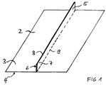
- FIG. 1 shows an aluminum foil 2 with a front surface (Front) 3 and a rear surface (back) 4.
- the aluminum foil 2 is by folding steps or Bending steps deformed in a partial area so that a Fold 5 is created with two fold surfaces 6 and 7, which in one Fold edge 8 converge.
- the two fold surfaces 6 and 7 are at the smallest possible distance from each other arranged and preferably touch on the inside, with a portion of the rear surface 4 of the Aluminum foil 2 are formed.
- To make the fold 5 the aluminum foil 2 becomes more parallel to one another along three Folded lines (fold lines) folded.
- the middle Fold line corresponds to the fold edge 8 of the fold 5, while the one to the right of the folded edge 8 in the illustration Kink line is designated 9.
- the crease line is hidden by fold 5 in the drawing.
- the two folding surfaces 6 and 7 of the fold 5 have the same height, measured as the distance from the Surface 3 of the aluminum foil 2, so that the folded edge 8 at a substantially equal distance from the Surface 3 of the aluminum foil 2 runs.
- the fold 5 provided with several cuts 10 to 13, preferably directed perpendicular to the surface 3 of the aluminum foil 2 are and preferably also up to the surface 3 reach down the aluminum foil 2.
- the one between the cuts 10 and 11 lying part of the fold 5 is on the Surface 3 of the aluminum foil 2 folded down a crease line 20 as well as that between the incisions 12 and 13 lying part of the fold 5.
- the folded down in this way Parts of the fold 5 form stabilizing elements 14 on the surface 3 of the aluminum foil 2 lie on.
- the incisions 11 and 12 and behind the incision 13 fold parts remain 15 'stand, each having two corners 16 and 17. These fold parts 15 'have the essentially one-dimensional Fold edge 8 of the original fold 5.
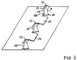
- FIG. 3 shows an exemplary embodiment for such a shaping of the folding elements.
- the fully formed folding elements are denoted by 15 and are by bending (folding) the corners 16 and 17 of the pleats 15 'in FIG. 2 formed.
- the corners 16 and 17 thus become the surface 3 of the Folded aluminum foil 2 that from the folded edge 8 in greatest distance from the surface 3 essentially one punctiform tip 25 remains and the rest of the fold edge 8 deeper, H. closer to surface 3 of the aluminum foil 2, is arranged. So it will be along Kink lines 18 essentially triangular wings 21 and 22nd with the corners 16 and 17 down to the surface 3 of the Folded aluminum foil 2.
- the two wings 21 and 22 can be supported in particular on the surface 3.
- the two wings 21 and 22 of the folding elements 15 folded in the opposite direction as shown are arranged or on the same side of the fold 5 his.
- the two wings 21 and 22 do not have to be arranged symmetrically so that the tip 25 of a Folding element 15 also against the center of the folding element 15 can be arranged shifted.
- the whole Folding element 15 also from the vertical to the surface 3 of the Aluminum foil 2 be inclined.
- the folding elements 15 can, for example, suitable roller tools and cutting tools suitable for the cutting processes be used.
- FIG. 4 shows an embodiment of an aluminum foil structure with an aluminum foil 2, which is arranged in a matrix Folding elements 15 with corresponding matrix arranged Tips 25 and between two folding elements 15 arranged stabilizing elements 14 according to FIG. 3rd having.
- Aluminum foil structures according to FIG. 3 or FIG. 4 can thus be in any Number stacked on top of each other by rear surface 4 of an aluminum foil 2 on the tips 25 of an underlying or overlying aluminum foil 2 is put on.
- the heat transfer between two with the folding elements 15 provided aluminum foils 2 due to the small contact areas over the tips 25 extremely low, so that with a stack of according to the Invention structured aluminum foils 2 an excellent Thermal insulation, especially for a furnace muffle Household appliances (oven, stove) can be reached.
- the stacked aluminum foil layers 2 are then wrapped around the oven muffle.
- folding elements also on both surfaces of the aluminum foil be staggered.
- the tips of the folding elements form the highest point of each folding element, measured from the film surface, but need not point away from the surface in a vertical direction, but can also be inclined against this direction.
- the actual surface area of the tips is generally less than 2 mm 2 , preferably less than 1 mm 2 .
Landscapes
- Engineering & Computer Science (AREA)
- General Engineering & Computer Science (AREA)
- Mechanical Engineering (AREA)
- Cookers (AREA)
- Baking, Grill, Roasting (AREA)
Description
- FIG. 1 bis 3
- die Ergebnisse von drei aufeinanderfolgenden Verfahrensschritten eines Verfahrens zum Herstellen einer Aluminiumfolienstruktur und
- FIG. 4
- ein Ausführungsbeispiel einer Aluminiumfolienstruktur
- 2
- Aluminiumfolie
- 3, 4
- Oberfläche
- 5
- Falte
- 6, 7
- Faltenfläche
- 8
- Faltenkante
- 9
- Knicklinie
- 10 - 13
- Einschnitte
- 14
- Stabilisierungselement
- 15
- Faltelement
- 15'
- Faltenteil
- 16, 17
- Ecke
- 18
- Knicklinie
- 20
- Knicklinie
- 21, 22
- Flügel
- 25
- Spitze
Claims (9)
- Aluminiumfolienstruktur mit wenigstens einer Aluminiumfolie (2) mit einer vorderen Oberfläche (3) und einer hinteren Oberfläche (4), wobei
a) die Aluminiumfolie (2) wenigstens an ihrer vorderen Oberfläche (3) wenigstens ein aus der Aluminiumfolie (2) gebogenes Faltelement (15) aufweist und dieses Faltelement (15) beim größten Abstand von der vorderen Oberfläche (3) in eine wenigstens annähernd punktförmige Spitze (25) zuläuft
dadurch gekennzeichnet, daß
b) die hintere Oberfläche (4) jeder Aluminiumfolie (2) wenigstens in einem unmittelbar dem Faltelement (15) gegenüberliegenden Teilbereich im wesentlichen eben ohne Einbuchtungen ist. - Aluminiumfolienstruktur nach Anspruch 1 mit mehreren Aluminiumfolienlagen, die derart übereinandergestapelt sind, daß ebene Teilbereiche einer Oberfläche einer Aluminiumfolienlage auf den Spitzen der Faltelemente der nächsten Aluminiumfolienlage aufliegen.
- Aluminiumfolienstruktur nach Anspruch 1 oder Anspruch 2, bei der jede Aluminiumfolie (2) mehrere Faltelemente (15) aufweist, deren Spitzen (25) matrixförmig angeordnet sind.
- Wärmeisolierung mit einer Aluminiumfolienstruktur nach einem der vorhergehenden Ansprüche.
- Haushaltsgerät mit einer Ofenmuffel, die mit einer Wärmeisolierung gemäß Anspruch 4 umgeben ist.
- Verfahren zum Erzeugen einer Aluminiumfolienstruktur, bei dema) in einem ersten Schritt in eine Aluminiumfolie (2) wenigstens eine Falte (5) mit zwei in einer von einer Oberfläche (3) der Aluminiumfolie (2) beabstandeten Faltkante (8) zusammenlaufenden und dicht beieinander angeordneten, vorzugsweise sich berührenden, Faltenflächen (6,7) gleichen Höhe gefaltet wird undb) in einem zweiten Schritt die Falte (5) zu wenigstens einem Faltelement (15) weiterverformt wird, das in dem größten Abstand von der Oberfläche (3) der Aluminiumfolie (2) in eine wenigstens annähernd punktförmigen Spitze (25) zuläuft, wobei die Faltenflächen (6,7) dicht beieinander angeordnet bleiben, vorzugsweise sich weiter berühren.
- Verfahren nach Anspruch 6, bei dem das wenigstens eine Faltelement (15) durch Verformen der Faltkante (8) der Falte (5) zur Oberfläche (3) der Aluminiumfolie (2) hin geformt wird.
- Verfahren nach Anspruch 6 oder Anspruch 7, bei dem die Falte (5) entlang wenigstens zweier Einschnitte (10,11,12,13) zur Oberfläche (3) der Aluminiumfolie (2) hin eingeschnitten wird und das Faltelement (15) durch Biegen der Ecken (16,17) des zwischen den beiden Einschnitten (11,12) liegenden Faltenteils (15') der Falte (5) zur Oberfläche (3) der Aluminiumfolie (2) hin geformt wird.
- Verfahren nach Anspruch 8, bei dem mehrere Einschnitte (10,11,12,13) in die Falte (5) erzeugt werden und die Falte (5) zwischen wenigstens zwei Einschnitten (10,11 oder 12,13) zur Oberfläche (3) der Aluminiumfolie (2) hin umgebogen wird, so daß sie im wesentlichen parallel zur Oberfläche (3) der Aluminiumfolie (2) zu liegen kommt.
Applications Claiming Priority (2)
| Application Number | Priority Date | Filing Date | Title |
|---|---|---|---|
| DE19631938A DE19631938A1 (de) | 1996-08-08 | 1996-08-08 | Aluminiumfolienstruktur und Verfahren zum Erzeugen einer Aluminiumfolienstruktur |
| DE19631938 | 1996-08-08 |
Publications (2)
| Publication Number | Publication Date |
|---|---|
| EP0823581A1 EP0823581A1 (de) | 1998-02-11 |
| EP0823581B1 true EP0823581B1 (de) | 2000-02-02 |
Family
ID=7802066
Family Applications (1)
| Application Number | Title | Priority Date | Filing Date |
|---|---|---|---|
| EP97109267A Expired - Lifetime EP0823581B1 (de) | 1996-08-08 | 1997-06-07 | Aluminiumfolienstruktur und Verfahren zum Erzeugen einer Aluminiumfolienstruktur |
Country Status (3)
| Country | Link |
|---|---|
| EP (1) | EP0823581B1 (de) |
| DE (2) | DE19631938A1 (de) |
| ES (1) | ES2143265T3 (de) |
Family Cites Families (2)
| Publication number | Priority date | Publication date | Assignee | Title |
|---|---|---|---|---|
| GB474370A (en) * | 1936-04-24 | 1937-10-25 | George Richardson | Improvements in or relating to heat insulation |
| US5011743A (en) * | 1990-01-22 | 1991-04-30 | Atd Corporation | Pad including heat sink and thermal insulation areas |
-
1996
- 1996-08-08 DE DE19631938A patent/DE19631938A1/de not_active Withdrawn
-
1997
- 1997-06-07 DE DE59701084T patent/DE59701084D1/de not_active Expired - Fee Related
- 1997-06-07 EP EP97109267A patent/EP0823581B1/de not_active Expired - Lifetime
- 1997-06-07 ES ES97109267T patent/ES2143265T3/es not_active Expired - Lifetime
Also Published As
| Publication number | Publication date |
|---|---|
| EP0823581A1 (de) | 1998-02-11 |
| ES2143265T3 (es) | 2000-05-01 |
| DE59701084D1 (de) | 2000-03-09 |
| DE19631938A1 (de) | 1998-02-12 |
Similar Documents
| Publication | Publication Date | Title |
|---|---|---|
| DE2546444A1 (de) | Waermeuebergangswand fuer siedende fluessigkeiten | |
| DE2243034B1 (de) | Elektrische kontaktanordnung | |
| DE2758041C2 (de) | Verwendung eines aus mindestens zwei übereinander angeordneten Folien, insbesondere Kunststoffolien, bestehenden Bauelements | |
| DE3610370C1 (de) | Einlage fuer eine Kabelverbindung | |
| DE2509784A1 (de) | Mischeinrichtung | |
| DE19741856A1 (de) | Rippe für einen Wärmeübertrager und Verfahren zur Herstellung von Rippendurchzügen in derartigen Rippen | |
| EP0823581A1 (de) | Aluminiumfolienstruktur und Verfahren zum Erzeugen einer Aluminiumfolienstruktur | |
| DE3425038A1 (de) | Randdaemmstreifen und verfahren zur verlegung | |
| EP0775867B1 (de) | Wärmeisolierende Umhüllung für wärmetechnische Geräte | |
| DE2854847C2 (de) | Wärmeisolierung mit reflektierenden Isolationsblechen | |
| EP0775866B1 (de) | Wärmeisolierende Umhüllung für wärmetechnische Geräte | |
| DE2306562A1 (de) | Waermetauscher | |
| DE8328912U1 (de) | Abdeckung fuer Materialpackungen oder -stapel insbesondere fuer palettiertes Packgut mit mehreckiger vorzugsweise rechteckfoermiger Grundriss- bzw Oberflaeche | |
| EP1225061B1 (de) | Klemmschiene | |
| EP1095876A1 (de) | Einen quaderförmigen Umkarton aufweisende Verpackung für eine Glasscheibe | |
| DE19755912B4 (de) | Wärmeisolierende Umhüllung | |
| DE69326827T2 (de) | Fugenvorrichtung | |
| AT397566B (de) | Mischkammeranordnung für brenner und verfahren zur herstellung derselben | |
| DE3443544A1 (de) | Toaster-aufsatz | |
| EP0525661A1 (de) | Schalung für den Betonbau sowie Verfahren zum Herstellen der Schalung | |
| DE626384C (de) | Verfahren zur Herstellung von Hohlkoerpern aus Papier o. dgl. | |
| EP0761143B1 (de) | Träger aus einem Pappenzuschnitt | |
| DE29913607U1 (de) | Heizung für den Trockenausbau | |
| DE19919117A1 (de) | Strukturierte Packung für Wasch- und Rektifiziersäulen | |
| DE20010349U1 (de) | Verpackungstragkörper |
Legal Events
| Date | Code | Title | Description |
|---|---|---|---|
| PUAI | Public reference made under article 153(3) epc to a published international application that has entered the european phase |
Free format text: ORIGINAL CODE: 0009012 |
|
| AK | Designated contracting states |
Kind code of ref document: A1 Designated state(s): CH DE ES FR GB IT LI SE |
|
| 17P | Request for examination filed |
Effective date: 19980226 |
|
| AKX | Designation fees paid |
Free format text: CH DE ES FR GB IT LI SE |
|
| RBV | Designated contracting states (corrected) |
Designated state(s): CH DE ES FR GB IT LI SE |
|
| 17Q | First examination report despatched |
Effective date: 19980923 |
|
| GRAG | Despatch of communication of intention to grant |
Free format text: ORIGINAL CODE: EPIDOS AGRA |
|
| GRAG | Despatch of communication of intention to grant |
Free format text: ORIGINAL CODE: EPIDOS AGRA |
|
| GRAG | Despatch of communication of intention to grant |
Free format text: ORIGINAL CODE: EPIDOS AGRA |
|
| GRAH | Despatch of communication of intention to grant a patent |
Free format text: ORIGINAL CODE: EPIDOS IGRA |
|
| GRAH | Despatch of communication of intention to grant a patent |
Free format text: ORIGINAL CODE: EPIDOS IGRA |
|
| GRAA | (expected) grant |
Free format text: ORIGINAL CODE: 0009210 |
|
| AK | Designated contracting states |
Kind code of ref document: B1 Designated state(s): CH DE ES FR GB IT LI SE |
|
| ITF | It: translation for a ep patent filed | ||
| REG | Reference to a national code |
Ref country code: CH Ref legal event code: NV Representative=s name: TROESCH SCHEIDEGGER WERNER AG Ref country code: CH Ref legal event code: EP |
|
| REF | Corresponds to: |
Ref document number: 59701084 Country of ref document: DE Date of ref document: 20000309 |
|
| ET | Fr: translation filed | ||
| REG | Reference to a national code |
Ref country code: ES Ref legal event code: FG2A Ref document number: 2143265 Country of ref document: ES Kind code of ref document: T3 |
|
| GBT | Gb: translation of ep patent filed (gb section 77(6)(a)/1977) |
Effective date: 20000407 |
|
| PGFP | Annual fee paid to national office [announced via postgrant information from national office to epo] |
Ref country code: ES Payment date: 20000613 Year of fee payment: 4 |
|
| PGFP | Annual fee paid to national office [announced via postgrant information from national office to epo] |
Ref country code: FR Payment date: 20000615 Year of fee payment: 4 |
|
| PLBE | No opposition filed within time limit |
Free format text: ORIGINAL CODE: 0009261 |
|
| STAA | Information on the status of an ep patent application or granted ep patent |
Free format text: STATUS: NO OPPOSITION FILED WITHIN TIME LIMIT |
|
| 26N | No opposition filed | ||
| PG25 | Lapsed in a contracting state [announced via postgrant information from national office to epo] |
Ref country code: GB Free format text: LAPSE BECAUSE OF NON-PAYMENT OF DUE FEES Effective date: 20010607 |
|
| PG25 | Lapsed in a contracting state [announced via postgrant information from national office to epo] |
Ref country code: ES Free format text: LAPSE BECAUSE OF NON-PAYMENT OF DUE FEES Effective date: 20010608 |
|
| GBPC | Gb: european patent ceased through non-payment of renewal fee |
Effective date: 20010607 |
|
| PG25 | Lapsed in a contracting state [announced via postgrant information from national office to epo] |
Ref country code: FR Free format text: LAPSE BECAUSE OF NON-PAYMENT OF DUE FEES Effective date: 20020228 |
|
| REG | Reference to a national code |
Ref country code: ES Ref legal event code: FD2A Effective date: 20030203 |
|
| PGFP | Annual fee paid to national office [announced via postgrant information from national office to epo] |
Ref country code: SE Payment date: 20040622 Year of fee payment: 8 |
|
| PG25 | Lapsed in a contracting state [announced via postgrant information from national office to epo] |
Ref country code: IT Free format text: LAPSE BECAUSE OF NON-PAYMENT OF DUE FEES;WARNING: LAPSES OF ITALIAN PATENTS WITH EFFECTIVE DATE BEFORE 2007 MAY HAVE OCCURRED AT ANY TIME BEFORE 2007. THE CORRECT EFFECTIVE DATE MAY BE DIFFERENT FROM THE ONE RECORDED. Effective date: 20050607 |
|
| PG25 | Lapsed in a contracting state [announced via postgrant information from national office to epo] |
Ref country code: SE Free format text: LAPSE BECAUSE OF NON-PAYMENT OF DUE FEES Effective date: 20050608 |
|
| EUG | Se: european patent has lapsed | ||
| PGFP | Annual fee paid to national office [announced via postgrant information from national office to epo] |
Ref country code: CH Payment date: 20070626 Year of fee payment: 11 |
|
| PGFP | Annual fee paid to national office [announced via postgrant information from national office to epo] |
Ref country code: DE Payment date: 20070628 Year of fee payment: 11 |
|
| REG | Reference to a national code |
Ref country code: CH Ref legal event code: PL |
|
| PG25 | Lapsed in a contracting state [announced via postgrant information from national office to epo] |
Ref country code: DE Free format text: LAPSE BECAUSE OF NON-PAYMENT OF DUE FEES Effective date: 20090101 |
|
| PG25 | Lapsed in a contracting state [announced via postgrant information from national office to epo] |
Ref country code: LI Free format text: LAPSE BECAUSE OF NON-PAYMENT OF DUE FEES Effective date: 20080630 Ref country code: CH Free format text: LAPSE BECAUSE OF NON-PAYMENT OF DUE FEES Effective date: 20080630 |