EP0822708B1 - Vorrichtung zum Erzeugen von Eingangsdaten für einen Interpolator - Google Patents
Vorrichtung zum Erzeugen von Eingangsdaten für einen Interpolator Download PDFInfo
- Publication number
- EP0822708B1 EP0822708B1 EP97100617A EP97100617A EP0822708B1 EP 0822708 B1 EP0822708 B1 EP 0822708B1 EP 97100617 A EP97100617 A EP 97100617A EP 97100617 A EP97100617 A EP 97100617A EP 0822708 B1 EP0822708 B1 EP 0822708B1
- Authority
- EP
- European Patent Office
- Prior art keywords
- color space
- interpolator
- memory
- bits
- values
- Prior art date
- Legal status (The legal status is an assumption and is not a legal conclusion. Google has not performed a legal analysis and makes no representation as to the accuracy of the status listed.)
- Expired - Lifetime
Links
Images


Classifications
-
- H—ELECTRICITY
- H04—ELECTRIC COMMUNICATION TECHNIQUE
- H04N—PICTORIAL COMMUNICATION, e.g. TELEVISION
- H04N1/00—Scanning, transmission or reproduction of documents or the like, e.g. facsimile transmission; Details thereof
- H04N1/46—Colour picture communication systems
- H04N1/56—Processing of colour picture signals
- H04N1/60—Colour correction or control
- H04N1/6016—Conversion to subtractive colour signals
- H04N1/6019—Conversion to subtractive colour signals using look-up tables
Definitions
- the present invention relates generally to digital data transformation and, more specifically, to generating data used for interpolation in a data transformation.
- Colorimetry has long been recognized as a complex science. In general, it has been found possible and convenient to represent color stimuli vectors in a three-dimensional space, called tristimulus space. Essentially, as defined in 1931 by the Commission Internationale L'Eclairage (CIE), three primary colors (X, Y, Z) can be combined to define all light sensations we experience with our eyes (that is, the color matching properties of an ideal trichromatic observer defined by specifying three independent functions of wavelength that are identified with the ideal observer's color matching functions form an international standard for specifying color).
- CIE Commission Internationale L'Eclairage
- Trichromatic model systems such as red, green, blue (RGB); cyan, magenta, yellow (CMY); hue, saturation, value (HSV); hue, lightness, saturation (HLS); luminance, red-yellow scale, green-blue scale (La*b*); luminance, red-green scale, yellow-blue scale (Luv); YIQ used in commercial color television broadcasting; and the like -- provide alternatives for the system designer. See such works as Fundamentals of Interactive Computer Graphics, by Foley and Van Dam, Addison-Wesley Publishing Company, incorporated herein by reference in pertinent parts, particularly pages 606 - 621, describing a variety of tri-variable color models.
- RGB red, green, and blue
- CMYK subtractive primary colors
- a transformation may require going from an RGB color space, for example, a computer video monitor, to a CMYK color space, for example, a laser printer hard copy.
- a transformation from one color space to another requires complex, non-linear computations in multiple dimensions. Some transform operations could be accomplished by multiplying a matrix of conversion constants by the set of values in the RGB color space which are to be transformed. Computation of the matrix of conversion constants is required for each set of values in the RGB color space which are to be transformed.
- RGB color space used for video displays uses eight bits to represent each of the primary colors, red, green, and blue. Therefore, twenty four bits are required to represent each picture element. With this resolution, the RGB color space would consist of 2 24 or 16,777,216 colors. Performing a color space conversion from each of these points in the RGB color space to generate the four CMYK (to maintain black color purity in printing, a separate black is usually provided rather than printing with all three of cyan, magenta, and yellow colorants to generate what is commonly known as process black) color space components would require a look-up table with 2 26 or 67,108,864 bytes of data. The empirical construction of a look-up table with this number of entries is too difficult and the hardware implementation cost of a color space converter employing this number of entries is prohibitive.
- the three groups of eight bits typically used to represent the primary colors may each be partitioned into a set of four higher order bits (e.g. RH, GH, BH) and a set of four lower order bits (e.g. RL, GL, BL).
- the three sets of higher order bits are used to form a set of addresses which provide access to an array of corresponding values in the color space to which the conversion is directed.
- An array of values exits for each of the color dimensions in the color space to which the conversion is directed.
- the sets of four lower order bits in each of RL, GL, and BL are used for interpolating between the values specified by the sets of four higher order bits in each of RH, GH, and BH.
- Each of the four arrays of values can be viewed as a cubic lattice in three dimensional space.
- each of the arrays must be expanded by one vertex on each of the three axes.
- a cubic lattice having 17 vertices in each of the dimensions contains a total of 4913 vertices.
- Each of the vertices internal to the cubic lattice is common to eight cubes. Each cube is formed from eight vertices.
- the conversion of a twenty four bit representation of an RGB color space value to one of the dimensions of the CMYK color space can be regarded as determining a location in the volume enclosed by a cube in the cubic lattice.
- the color space values represented by the eight vertices of the cube are used in determining this location.
- the twelve bits formed from RH, GH, and BH are used as an address to locate one vertex of the cube in the cubic lattice.
- the addresses of the remaining seven associated vertices of the cube are determined by forming the remaining possible combinations of the values of RH, GH, BH, RH + 1, GH + 1, and BH + 1.
- the twelve bits formed from RH, GH, and BH serve to select an entry vertex into the cubic lattice to define a cube within which an interpolation will be performed.
- the seven other vertices which make up the cube are identified by their spatial relationship to the entry vertex.
- the entry vertex of the cube will be the one vertex of eight vertices forming the cube located the closest to the origin of the three dimensional space containing the cubic lattice.
- the vertices of selected cubes will have the same relative orientation in the cubic lattice.
- the values corresponding to the vertices of the cubic lattice are typically stored in a memory and accessed using the addresses formed from RH, GH, and BH.
- addresses formed from RH, GH, and BH.
- the look-up table values must be distributed in memory to allow access in the most efficient manner.
- EP 0 601 241 A1 describes a method for color transformation, wherein for transforming source color values of a source color space into corresponding target color values of the target color space, the color values of the source color space are quantized and each source color value has associated a quantized source color value. Target color values corresponding to the quantized source color values are determined and for each transformed source color value four corresponding target color values are determined, the color portions of which are multiplied by weighting factors. The sum of the weighted color portions are the color portions of the corresponding target color value in the target color space.
- a first table is provided for storing coordinates of a target color triple corresponding to a source color triple. In a second table, a pointer and four weighting coefficients are stored.
- EP 0 723 248 A2 describes an implementation of a multi-dimensional, non-linear interpolation using a look-up table combined with an interpolator suited for color spaced transformations.
- a device for transforming multi-variable, non-linear input data and for providing interpolated output data includes a set of two high ranking n memory banks, where n is the number of variables.
- An address generating logic is connected to the memory input and a sorting logic is connected to the memory output.
- the interpolating logic receives input output by the memory banks which are sorted by the sorting logic and outputs interpolated data.
- US-A-5,432,892 describes a volumetric linear interpolation of an allowable range of input values defining a domain.
- the sample points for the interpolation are chosen such that there are 16 intervals for each input component, yielding a total of seventeen values.
- Three extreme values situated outside the domain are evaluated and this evaluation is based on the assumption that the function is continuous outside the domain. These points are outside the domain, but they are required in order to compute approximate values for certain points situated within the domain and the function values at the sample points are computed and saved in the three-dimensional array having 17 x 17 x 17 entries.
- the present invention provides an apparatus for generating interpolator input data used for a transformation of input data values having n components to output data values each having i components has been developed.
- the input data values may represent an input color space, such as a RGB color space.
- the output data values may represent an output color space, such as a CMYK color space.
- the apparatus can generate interpolator input data when the input data values to be transformed lie on the outer boundaries of the input color space.
- the n components are represented by n sets of bits which have each been partitioned to form n sets of higher order bits.
- the apparatus uses m bits corresponding to the n sets of higher order bits.
- the apparatus includes an address generator arranged for receiving the m bits. In response to the m bit input, the address generator can generate at least ⁇ [2 m 1 + 1] ⁇ [2 m 2 + 1] ⁇ ... ⁇ [2 m n + 1] ⁇ addresses.
- the apparatus also includes a memory for storing interpolator input data corresponding to each of the possible address values. In response to receiving an address from the address generator, the memory outputs the corresponding interpolator input data.
- the exemplary embodiment of the apparatus for generating interpolator input data will be discussed in the context of a color space conversion from an RGB color space to a CMYK color space, it will be recognized by one skilled in the art that the disclosed apparatus for generating interpolator input data is useful for other applications requiring the use of an interpolator to perform a data transformation. Furthermore, while the operation of the exemplary embodiment will be described in terms of a three dimensional space and an interpolator using eight interpolator input data values to define the region in which interpolation is performed, it will be recognized that this apparatus for generating interpolator input data may be modified to operate in a n-dimensional space.
- the exemplary color space conversion apparatus uses 14 input bits to generate the interpolator input data used for the color space conversion
- the color space conversion apparatus may be configured to use m bits for generating the necessary interpolator input data.
- interpolator input data refers to the data set used by an interpolator to define the bounds of the region in which the interpolation is performed.
- the look-up table used for the color space conversion is formed from the interpolator input data values.
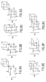
- each of the vertices of the cube 1 in a cubic lattice can be specified by a set of address vectors, RH, GH, and BH.
- the set of address vectors which address the locations of the cube vertices containing the corresponding values may be represented as shown in Figure 1.
- Each of the addresses of the vertices shown have address vectors which, for at least one of the dimensions, differ in their values by 1. Any set of eight vertices forming a cube in the cubic lattice can be addressed in this manner.
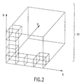
- the cubic lattice 10, a portion of which is shown in Figure 2, is formed from a three dimensional matrix of vertices.
- Each of the vertices in the cubic lattice 10 has a corresponding address for the color space value represented by the vertex.
- the addresses of the locations having the values represented by the vertices are determined by the values of RH, GH, and BH.
- Each of the dimensions of the cubic lattice which correspond to R, G, and B are labeled in Figure 2. It will be recognized by inspection of the Figure 2, that vertices are shared between the cubes in the cubic lattice 10.
- the values of RH, GH, and BH are used to address a value corresponding to a vertex in the cubic lattice.
- seven associated values corresponding to the remaining seven vertices of the cube selected by the values RH, GH, and BH, are used to perform the interpolation. Referring to Figure 3, the interpolation is performed using the formulas contained in the interpolator blocks.
- RL', GL', and BL' are used, according to the formulas shown in the blocks in Figure 3, by the interpolator to compute the location within the corresponding cube which corresponds to one of the dimensions in the CMYK color space. This location is the output of the interpolator indicated by the block labeled "RESULT" in Figure 3.
- the eight values associated with the vertices of the selected cube are connected to the inputs of the interpolator as shown in Figure 3.
- the apparatus for generating interpolator input data of this embodiment is compatible with interpolation processes other than a cubic interpolation.
- a tetrahedral interpolation uses 4 values to bound the region over which interpolation is performed and a prismatic interpolation uses 6 values.
- Each of the cubes can be partitioned into either tetrahedrons or prisms with selected vertices of cube serving as the vertices of the tetrahedrons or the prisms.
- the desired tetrahedron or prism can be formed to perform tetrahedral or prismatic interpolations. Determination of which of the eight values accessed by the apparatus for generating interpolator input data will be used to perform a tetrahedral or prismatic interpolation can be done while the memory containing the interpolator input data values is accessed.
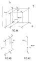
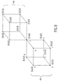
- Shown in Figure 4 is a graphic representation of the steps in the interpolation process which are accomplished using the interpolator of Figure 3.
- An addressed cube 1 of the cubic lattice 10 is shown.
- the top row of interpolation calculations in Figure 3 uses the RL' set of bits and the eight values a0-a7 to generate four values b0-b3 which define the plane 21 shown. These four points b0-b3 in this plane correspond to the four values b0-b3 resulting from the top row of interpolation calculations.
- the eight values a0-a7 correspond to the eight vertices of the addressed cube 1.
- the GL' set of bits along with the four values b0-b3 from the top row are used in the second row of interpolation calculations to compute two values c0-c1 which define the line 22 shown.
- the two points c0-c1 correspond to the two values c0-c1 resulting from the second row of interpolation calculations.
- the BL' set of bits along with the two values c0-c1 from the second row are used in the third row of interpolation calculations to compute the result.
- the point labeled "RESULT" corresponds to the result of the interpolation calculation and is located in the volume enclosed by the cube 1.
- the twenty four bit RGB color space value is partitioned into twelve bits of RH, GH, and BH, and twelve bits of RL, GL, and BL
- the partition of the twenty four bits could be made so that fifteen bits are dedicated to RH, GH, and BH, and nine bits are dedicated to RL, GL, and BL.
- fifteen bits are designated as higher order bits, six bits may be assigned to RH, four bits to GH, and five bits to BH.
- the cubic lattice 10 formed from the vertices is a representation of the array of values in a look-up table storing data used for interpolation.
- a difficulty occurs when attempting an interpolation using a vertex located at the outer boundary of the RGB color space in at least one of the dimensions. This would occur when at least one of RH, GH, or BH has the binary value of 1111. In these cases, the vertex addressed would be located on the outer boundary of at least one of the dimensions of the cubic lattice 10 representing the color space.
- Interpolator input data could not be generated because, depending upon the specific location of the addressed vertex on the outer boundary, interpolator input data values corresponding to the seven associated vertices do not exist.
- the cubic lattice representing the look-up table data is expanded to have 17 vertices in each of the three color space dimensions R, G, and B.
- This results in a look-up table having 17 3 4913 entries for each dimension of the color space to which the conversion is performed.
- the look-up table would require four times this number of values or 19,652 values.
- the addresses used to address data stored in the look-up table must have sufficient numbers of bits to address the 19,652 values in the look-up table. It will be recognized that the expansion of the representative cubic lattice may be done for different partitions of the twenty four bits between the higher order bits and the lower order bits and for unequal distribution of the higher order bits between RH, GH, and BH.
- the expansion of the data in the look-up table may be done for the general case of a transformation from input data values each having n components to output data values each having i components.
- the memory which stores the interpolator input data values could store the values for performing conversion to a single one of the i dimensions of the output color space or it could store the interpolator input data values for all of the i dimensions.
- the interpolator input data values stored in the memory could be configured so that a single one of the required eight values used for conversion to one of the i dimensions of the output color space is accessed at a time, or all eight values are accessed substantially simultaneously.
- a single interpolator may be used or an interpolator may be used for each of the i dimensions of the output color space.
- a single interpolator would load the interpolator input data values as they are output from the memory and perform the interpolation after all eight of the values have been loaded.
- the memory Before color space conversion is performed for each of the four dimensions of the output color space, the memory would be loaded with the set of interpolator input data corresponding to the dimension of the output color space to which the conversion is directed. Although this option requires the minimum hardware, it yields the slowest conversion speed of the possible options.
- a second option would involve storing the interpolator values necessary to perform the interpolation for one of the dimensions of the output color space in memory so that all eight of the values necessary for conversion of one of the input data values are accessed and output to the interpolator substantially simultaneously.
- the memory would be divided into eight separate banks with each bank storing one of the eight interpolator input data values.
- This second option would use a single interpolator and the memory may either store the interpolator input data values for all of the i dimensions or only for a single dimension.
- a third option would store the interpolator input data values used for conversion to all i dimensions of the output color space in memory so that all eight interpolator input data values for each of the i dimensions could be accessed substantially simultaneously. Each of the i sets of eight interpolator input data values would be loaded into one of i interpolators so that the color space conversion to each of the i dimensions of the output color space is performed substantially simultaneously.
- This third option achieves the greatest conversion speed but requires the most hardware. Other possible combinations of memory configurations and interpolation processes are possible.
- the preferred embodiment of the color space conversion apparatus uses eight banks of static random access memory (SRAM) each containing four sets of values, corresponding to the vertices in four cubic lattices, for conversion to each of the dimensions of the CMYK color space.
- SRAM static random access memory
- Other types of memory such as dynamic random access memory (DRAM), read only memory (ROM), or flash memory may be used instead of SRAMs.
- DRAM dynamic random access memory
- ROM read only memory
- flash memory may be used instead of SRAMs.
- the eight memory banks are preloaded with the interpolator input data prior to the beginning of the color space conversion.
- Each memory bank provides one of the eight values corresponding to the vertices of a cube for one of the dimensions of the CMYK color space.
- the memory contains the values for all four of the CMYK color space dimensions, but the set of values for each of the four dimensions is accessed only when an interpolation is performed for the corresponding dimension of the color space. This approach is well suited for a color print engine which sequentially prints the color planes of the image.
- FIG. 6 Shown in Figure 6 is block diagram of a color space conversion apparatus 40 including the apparatus for generating interpolator input data 41. Included in the apparatus for generating interpolator input data 41 are a memory 42 and an address generator 43.
- the memory 42 includes eight separate banks 42a-42h for storing the interpolator input data values. Each of the memory banks 42a-42h includes a memory address input and a memory data output
- the inputs to the apparatus for generating interpolator input data 41 include the three sets of higher order bits RH, GH, and BH from a twenty four bit RGB color space value and two CMYK bits which select one of the CMYK dimensions for the color space for conversion. In general, j bits may be used to select one of an arbitrary number of dimensions in the output color space.
- each of RH, GH, and BH are formed from four bits.
- Each of the address outputs of the address generator 43 include eight sets of twelve bits, one for each of the eight memory banks 42a-42h.
- the memory data outputs of the memory 42 include eight sets of eight bits (one set of eight bits for each of the eight memory banks 42a-42h). Each of these eight sets of bits is coupled to one of the eight interpolator inputs a0-a7 of the hardware interpolator 44.
- the three sets of lower order bits RL, GL, and BL as well as the least significant bit of the three sets of higher order bits RH, GH, and BH are inputs to a selective two's complementer 45 which selectively generates the two's complement of RL, GL, and BL.
- the output of the selective two's complementer 45 RL', GL', and BL' are input to the hardware interpolator 44.
- Each of the eight sets of twelve bits output from the address generator 43 include two bits which are used for selection of one of four sets of interpolator input data values stored in memory 42 which correspond to one dimension of the CMYK color space. The remaining eight sets of ten bits are used to select vertices in the cubic lattice corresponding to the dimension of the CMYK color space to which the conversion is directed.
- With twelve bits going to each of the eight memory banks 42a-42h there is the capability of addressing 2 12 4096 locations in each of the eight memory banks 42a-42h, for a total of 32,768 locations.
- memory 42 contain 32,768 locations to perform a RGB to CMYK colors space conversion using an expanded cubic lattice with 17 vertices for each dimension of the cubic lattice.
- the locations in memory 42 correspond to the addresses of the vertices in four cubic lattices, one cubic lattice for each dimension of the CMYK color space to which the conversion is directed.
- the locations will be partitioned between each of the eight memory banks 42a-42h so that access to the eight values associated with the vertices of any cube in the cubic lattice for any of the four dimensions can be performed by substantially simultaneously accessing each of the eight memory banks 42a-42h once.
- substantially simultaneously refers to the access of the eight values at approximately the same instant within the inherent variability in the memory access times between each of the memory banks 42a-42h.
- the partitioning of the locations in memory 42 determines the required set of outputs of the address generator in response to the inputs RH, GH, and BH and the two bits used to select the color space conversion dimension.
- a concept of the evenness or oddness of the address corresponding to a vertex in the cubic lattice is used to assign the corresponding value for storage in a location in one of the eight memory banks 42a-42h.
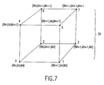
- the cube 1 is shown with the addresses corresponding to each of the vertices.
- the set of relative addresses for the eight vertices includes: ⁇ RH, GH, BH, ⁇ ⁇ RH, GH + 1, BH ⁇ ⁇ RH, GH, BH + 1 ⁇ ⁇ RH, GH + 1, BH + 1 ⁇ RH + 1, GH, BH ⁇ ⁇ RH + 1, GH, BH+1 ⁇ (RH + 1, GH + 1, BH ⁇ ⁇ RH + 1, GH + 1, BH + 1 ⁇ .
- An address to a vertex in the cubic lattice formed from RH, GH, and BH serves as an entry address into the cubic lattice to generate the eight values associated with the eight vertices of a cube in the cubic lattice.
- the address generator 43 In response to an entry address of a vertex in the cubic lattice, the address generator 43 generates the eight addresses corresponding to the above listed group of relative addresses so that the eight corresponding values can be loaded from memory 42 into the hardware interpolator 44.
- a cubic lattice having 17 vertices in each of its three dimensions can have each of its vertices uniquely labeled so that the vertex at the origin has a label of (0,0,0) and the vertex at the greatest distance from the origin has a label of (16,16, 16).
- Each of the vertices of the cubic lattice can be categorized according to the oddness or evenness of its components. For example, the vertex with the label (1,2,3) would be categorized as (O,E,O).
- each of the vertices will have a unique categorization relative to the other vertices with respect to the evenness or oddness of the associated label. That is, each vertex in the cubic lattice will have one of the following categorizations with respect to evenness or oddness of its associated address: (E,E,E), (E,E,O), (E,O,E), (O,E,E), (E,O,O), (O,E,O), (O,O,E), (O,O,O).
- the number of vertices included in each the eight evenness and oddness categorizations can be computed. For integers ranging from 0 to 16, there are nine even values (0, 2, 4, 6, 8, 10, 12, 14, 16) and eight odd values (1, 3, 5, 7, 9, 11, 13, 15).
- the sum of the numbers of memory locations in the table for each category equals 19,652, which, as was shown earlier, is the number of memory locations required for a color space conversion to all dimensions of the CMYK color space.
- 12 bits are sufficient to address all the memory locations in each of the eight memory banks.
- the memory bank categorized as (O,O,O) requires only 11 bits to access its 2048 storage locations. Because of this, only 11 bits are used to access the storage locations for the (O,O,O) memory bank.
- a partition is formed which will allow any eight values corresponding to the eight vertices of a cube in the cubic lattice to be loaded into the hardware interpolator 44 with a single simultaneous access to each of the eight memory banks 42a-42h.
- twelve address bits provided to each of the eight memory banks 42a-42h there is a sufficient number of bits to address 4096 memory locations for each one of the eight memory banks 42a-42h for a total of 32,768 memory locations.
- the eight outputs of the address generator 43 generate addresses for only the 19,652 locations in the eight memory banks 42a-42h corresponding to the values in the expanded look-up table.
- color space conversion apparatus 40 is implemented entirely on an application specific integrated circuit (ASIC).
- ASIC application specific integrated circuit
- This implementation requires that the layout of memory 42 minimize the usage of die space on the ASIC.
- Seven of the eight memory banks 42a-42h must store a number of bytes in between the closest standard RAM sizes of 2048 bytes and 4096 bytes.
- the RAM corresponding to those addresses having an (O,O,O) categorization must store 2048 bytes.
- custom sized RAMs for the seven of the eight memory banks 42a-42h which must store non-standard numbers of bytes, more efficient utilization of ASIC die space can be achieved.
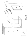
- Figure 13 illustrates a partition of the cubic lattice representing the data values in the expanded look-up table.
- the cubic lattice 10 having 16 vertices in each of the R, G, and B dimensions, represents 4096 data values.
- the R face 70 represents the 256 data values associated with the expansion of the cubic lattice in the R dimension by one vertex.
- the G face 71 and the B face 72 also represent 256 data values each resulting from expansion of the cubic lattice 10 in the G and B dimensions by one vertex, respectively.
- the BG 73, RB 74, and RG 75 "bars" (the BG, RB, and RG designations originate from the location of the bars at the intersections of the respective faces) represent edges which lie at the intersection of the R, G, and B faces. Each of these bars represents 16 data values in the expanded look-up table.
- the RGB cube 76 represents the data value associated with the vertex having the label (16, 16, 16). As it should, the number of data values for the 16 vertex/axis cubic lattice (4096), the R face (256), the G face (256), the B face (256), the BG bar (16), the RB bar (16), the RG bar (16) and the RGB cube (1) sum to 4913.
- the memory banks 42a-42h store data values for four of these expanded cubic lattices, one for conversion to each dimension of the CMYK output color space.
- Address generator 43 allows the use of the custom sized RAMs for the eight memory banks 42a-42h.
- Address generator 43 maps the 12 bit concatenated RH, GH, and BH value and the two CMYK selection bits into eight twelve bit addresses, one for each of the eight memory banks 42a-42h.
- the four higher order bits for each of the dimensions of the RGB color space are designated from most significant to least significant as: RH(7), RH(6), RH(5), RH(4), GH(7), GH(6), GH(5), GH(4), BH(7), BH(6), BH(5), BH(4).
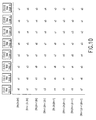
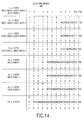
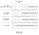
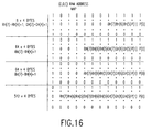
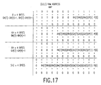
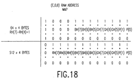
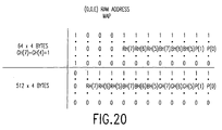
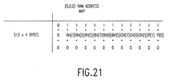
- Shown in Figures 14 through 21 are a series of tables which show the range of address values generated for each of the eight memory banks 42a-42h.
- the tables categorize the generated addresses based upon the portions of the expanded cubic lattice shown in Figure 13 which contain the data values addressed.
- the tables also show which of the higher order bits are used to determine addresses within each of the categories. As is indicated in the tables, the higher order bits of the dimensions of the RGB input color space which are not directly used to generate the addresses are used to select the category.
- the bits of the addresses designated as "P(0)" and "P(1)" represent the CMYK selection bits.
- P(0) and P(1) bits may be assigned to represent each of the dimensions of the output color space is shown below: P(1) P(0) OUTPUT COLOR SPACE DIMENSION 00 Yellow 01 Magenta 10 Cyan 11 Black
- the methods used to design address generator 43 to generate the addresses in the tables of Figures 14 through 21 are well known to one of ordinary skill in the art of digital design.
- the hardware interpolator 44 performs the interpolation on the values represented by the eight vertices of the cube as shown in Figure 3. It will be understood by one skilled in the art that presentation of the values from the outputs of the eight memory banks 42a-42h to the eight inputs of the hardware interpolator 44 must be done with regard to the location of the vertex in the cube to which the values correspond, to obtain the correct output from the hardware interpolator 44.
- the method of design of hardware interpolator 44 is well known to one skilled in the art of digital design.
- the block diagram of the interpolation process shown in Figure 3 is that of a parallel cascade interpolator.
- hardware interpolator 44 may be of the parallel cascade or the serial iterative type.
- the parallel cascade type uses a hardware computation block for each computation in the interpolation process to perform the interpolation more rapidly at the expense of increased hardware requirements.
- the serial iterative type uses a single hardware computation block repeatedly so that it requires less hardware at the expense of decreased computation speed.
- a single parallel cascade interpolator is used to perform the interpolation computations for each of the four dimensions of the output CMYK color space a single dimension at a time.
- the color space conversion may be performed more rapidly by using four interpolators to perform the interpolation for each of the dimensions substantially simultaneously. This implementation would, of course, greatly increase the hardware requirements.
- the cube 50 is shown with the relative addresses of the vertices and also a numbering of the vertices. Shown in Figure 8 are the cubes formed when considering each of the remaining seven numbered vertices as the initial address for entry into the cubic lattice so that the selected vertex has the same orientation with respect to its seven associated vertices as the vertex numbered 0 of cube 60. For illustrative clarity, each of the seven cubes associated with cube 60 have been shown separately. The relative addresses of the eight vertices of a cube will be associated with the same vertex number within any cube in the cubic lattice.
- the cubic lattice includes a plurality of cubes having a numbering corresponding to cube 60 based upon the orientation of the cube in the cubic lattice.
- each of the memory bank 42a-42h outputs is hardwired to interpolator inputs a0-a7, respectively.
- the values represented by the vertices 0-7 of any cube must be logically connected to the corresponding inputs a0-a7 of the interpolator depending upon the evenness or oddness characterization of the vertex used for entry into the cubic lattice. This is complicated by the storage of the eight values in the eight memory banks 42a-42h based upon the evenness or oddness of the address of the vertices in the cubic lattice.
- Shown in Figure 10 is a table having a listing of the interpolator inputs (a0-a7) of Figure 3 to which the memory outputs of memory bank 42 should be directed.
- the table of Figure 10 was generated by selecting a cube in the cubic lattice with the vertex numbered 0 having the address (RH, GH, BH) assigned to it. Then, for the case of each of the eight vertices of the selected cube ⁇ listed by their addresses relative to (RH, GH, BH) ⁇ successively becoming the initial address for entry into the cubic lattice to perform a color space conversion, listing the interpolator inputs to which the memory outputs should be logically connected for the eight vertices forming the cube.
- the interpolator inputs to which the eight memory bank 42a-42h outputs (as designated by the headings for each column) should be logically connected are listed in the row associated with the relative address.
- the logical connection between the memories and the interpolator inputs is as follows: (E,E,E) (O,E,E) (E,O,E) (O,O,E) (E,E,O) (O,E,O) (E,O,O) (O,O,O) a4 a5 a6 a7 a0 a1 a2 a3
- the respective output value will be logically connected to each of the interpolator inputs depending upon the address of the vertex used as the entry into the cubic lattice.
- the outputs of the eight memory banks 42a-42h are connected, respectively, to the inputs a0-a7 of interpolator 43.
- the vertex labeled 0 is catagorize with respect to evenness and oddness as (E,E,E)
- the result of the interpolation will be correct using RL, GL, and BL without the two's complement operation applied.
- the selective two's complementer 45 includes the capability to selectively perform the two's complement function on one or more of RL, GL, and BL in response to the evenness or oddness categorization of, respectively, RH, GH, and BH as indicated in Table 3.
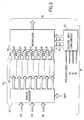
- Shown in Figure 11 is the preferred embodiment of the selective two's complementer 45 of Figure 6.
- the least significant bit ⁇ RH(4), GH(4), and BH(4) ⁇ of each of the higher order groups of bits is used to control the selective performance of the two's complement operation on, respectively, RL, GL, and BL.
- the bits RH(4), GH(4), and BH(4) have a value of 1, the corresponding RH, GH, and BH will be odd and thus require that a two's complement be performed on the respective RL, GL, and BL.
- the selective two's complementer 45 includes three separate two's complementers 45a-45c, one for each of RL, GL, and BL.
- Each of the three two's complementers 45a-45c includes a set of exclusive OR gates 45a1-45c4 and a binary incrementer 45a5-45c5.
- the input to each of the sets of exclusive OR gates 45a1-45c4 consists of the four bits from each of RL, GL, and BL and the least significant bits RH(4), GH(4), and BH(4), respectively.
- Each of the binary incrementers 45a5-45c5 adds the value of the associated RH(4), GH(4), and BH(4) bit to the outputs of the exclusive OR gates 45a1-45c4.
- the output of each of the binary incrementers 45a5-45c5 includes five bits.
- the two's complement is performed by selectively inverting the RL, GL, or BL (depending upon whether the corresponding RH(4), GH(4), or BH(4) bits are odd) using the exclusive OR gates 45a1-45a3, 45b1-45b3, and 45c1-45c3 and adding, respectively, RH(4), GH(4), and BH(4) to the result using the binary incrementers 45a5-45c5.
- the techniques used to design selective two's complementer 45 are well know to one skilled in the art of digital design.
- the preferred embodiment of the color space conversion apparatus 40 is implemented in an ASIC for maximizing the speed of the color space conversion.
- the functions performed by the ASIC implementation of the color space conversion apparatus may be accomplished using a microprocessor.
- the functions accomplished using the dedicated hardware of the selective two's complementer 45 may be accomplished through the operation of a microprocessor.
- the functions performed by the hardware interpolator 44 and address generator 43 may also be accomplished using a microprocessor. In using a microprocessor a tradeoff would be made between the simplicity of the hardware design of the color space converter and the conversion speed.
- Shown in Figure 12 is a flow diagram of a method for generating interpolator input data using the preferred embodiment of the apparatus for interpolator input data generation.
- the eight memory banks 42a-42h Prior to the generation of the interpolator input data, the eight memory banks 42a-42h must be loaded 100 with interpolator input data values corresponding to the vertices of the cubic lattice of each of the dimensions of the output color space to which the conversion is directed. This memory initialization step is performed prior to the start of the color space conversion and is not repeated as successive RGB input data values undergo color space conversion.
- the address generator 43 loads 101 the higher order bits RH, GH, BH and the CMYK bits for selecting the dimension in the output color space to which the conversion is directed. Then, the address generator 43 generates 102 the eight addresses corresponding to the vertices of the cube defined by the loaded higher order and CMYK bits. Next, the eight addresses are used for accessing 103 the eight memory banks 42a-42h. Finally, each of the eight memory banks 42a-42h outputs 104 a data value for each of the eight inputs of the interpolator.
- the cubic lattice used for interpolation in the conversion to each of the dimensions of the output CMYK color space includes 16 vertices along each axis for a total of 4096 vertices in each of the four cubic lattices.
- the 4096 interpolator input data values are partitioned into eight standard size 512 byte memory banks. The eight memory banks are loaded with the 4096 interpolator input data values corresponding to the dimension of the output CMYK color space to which the conversion is directed.
- the disclosed apparatus for generating interpolator input data of this application generates addresses to access the interpolator input data values corresponding to each of four, 4096 vertex cubic lattices and the expanded portions of the cubic lattice corresponding to the 17th vertex on each axis.
- This requires hardware in the address generator which detects the special case in which one or more of RH, GH, and BH has a binary value of 1111 and generates the addresses necessary to access those interpolator input data values corresponding to the vertices which are located in the expanded portions of the cubic lattice. This capability is not present in the address generator disclosed in Jones.
Landscapes
- Engineering & Computer Science (AREA)
- Multimedia (AREA)
- Signal Processing (AREA)
- Facsimile Image Signal Circuits (AREA)
- Color Image Communication Systems (AREA)
- Image Processing (AREA)
- Dot-Matrix Printers And Others (AREA)
Claims (6)
- Ein Farbraumumwandler (40) zur Umwandlung von Farbraumeingabedaten aus einem Eingabefarbraum, der n Dimensionen aufweist, die durch n Komponenten dargestellt sind, aufweist, in Farbraumausgabedaten in einem Ausgabefarbraum, der i Dimensionen, die durch i Komponenten dargestellt sind, aufweist, wobei die n Komponenten durch n Sätze von Bits dargestellt sind, die jeweils in einen Satz aus höherwertigen Bits und einen Satz aus niederwertigen Bits geteilt sind, wobei der Farbraumumwandler (40) folgende Merkmale aufweist:einen Adreßgenerator (43) zur Erzeugung von {[2m1 + 1] x [2m2 + 1] x ... x [2mn + 1]} Adressen, wobei mx, x = 1 ... n die Anzahl der höhergeordneten Bits in der x-ten Komponente der Eingabedatenwerte ist, wobei der Adreßgenerator (43) m Bits erhält, bei dem m = m1 + m2 + ... + mn gilt;einen Speicher (42), der {[2m1 + 1] x [2m2 + 1] x ... x [2mn + 1]} Speicherstellen aufweist und die Interpolatoreingabedaten an diesen Stellen speichert, wobei der Speicher (42) eine Mehrzahl von Speicherbänken (42a - 42h) aufweist, die jeweils einen Speicheradreßeingang, der die Adressen von dem Adreßgenerator (43) empfängt, und einen Speicherdatenausgang aufweist, wobei sich eine Zuordnung der Speicherstellen zu den Speicherbänken (42a - 42h) gemäß einer Kategorisierung nach Geradzahligkeit und Ungeradzahligkeit der Interpolatoreingabedaten, die in den Speicherstellen gespeichert sind, auftritt, wobei die Kategorisierung nach Geradzahligkeit und Ungeradzahligkeit der Interpolatoreingabedaten von den Koordinatenwerten in einem Würfelgitter, das den Interpolatoreingabedatenwerten zugeordnet ist, abhängt, wobei ein gerader Koordinatenwert in eine Geradzahligkeitskategorisierung resultiert, und ein ungerader Koordinatenwert in eine Ungeradzahligkeitskategorisierung resultiert;einen Interpolator (44), der eine Anzahl von Dateneingängen besitzt, die der Anzahl der Speicherdatenausgänge entspricht, wobei der Interpolator (44) Interpolatorausgangsdaten ausgibt, wobei die Verbindung der Speicherdatenausgänge mit den Interpolatoreingangsdaten fest ist; undeine Einrichtung zum Ausführen eines selektiven Zweierkomplements (45), die mit dem Interpolator (44) verbunden ist, wobei die Einrichtung zum Durchführen eines selektiven Zweierkomplements (45) für einen Empfang der n Sätze von niederwertigen Bits und ein niederstwertiges Bit aus jedem der n Sätze der höherwertigen Bits angeordnet ist, wobei die Einrichtung zum Durchführen eines selektiven Zweierkomplements (45) für die selektive Durchführung eines Zweierkomplements der n Sätze von niederwertigen Bits in Bezug auf den Zustand der entsprechenden niederstwertigen Bits und zum Schaffen eines selektiven Zweierkomplements aus den n Sätzen der niederwertigen Bits für jeden Interpolator (44) vorgesehen ist.
- Die Vorrichtung (41) gemäß Anspruch 1, bei der:der Adreßgenerator (43) eine Fähigkeit für einen Empfang von j Bits zum sukzessiven Auswählen von einer der i Dimensionen, in die die n Komponenten zu transformieren sind, aufweist;der Adreßgenerator (43) ({[2m1 + 1] x [2m2 + 1] x ... x [2mn + 1]} x i) Adressen erzeugt; undder Speicher (42) ({[2m1 + 1] x [2m2 + 1] x ... x [2mn + 1]} x i) Speicherstellen aufweist.
- Die Vorrichtung (43) gemäß Anspruch 1 oder 2, bei der:n gleich 3, i gleich 4 und j gleich 2 ist; undder Speicher (42) acht Speicherbänke (42a - 42h) aufweist.
- Die Vorrichtung (41) gemäß Anspruch 3, bei der:der Adreßgenerator (43) acht Adreßausgänge aufweist, die jeweils an einen der Speicheradreßeingänge gekoppelt sind, wobei der Adreßgenerator (43) acht der Adressen im wesentlichen gleichzeitig in Reaktion auf den Empfang der m Bits und der j Bits erzeugt;m1, m2 und m3 gleich jeweils 4 sind; undder Eingabefarbraum einen Farbraum aufweist, der aus der Gruppe, bestehend aus einem RGB-, einem Lab-, einem XYZ-, einem HSV-, einem Luv- und einem HLS-Farbraum, ausgewählt ist, wobei der Ausgabefarbraum einen CMYK-Farbraum aufweist.
- Der Farbraumumwandler (40) gemäß einem der Ansprüche 1 bis 3, bei dem:der Eingabefarbraum einen Farbraum aufweist, der aus der Gruppe, bestehend aus einem RGB-, einem Lab-, einem XYZ-, einem HSV-, einem Luv-, einem HLS-, einem CMYK-Farbraum, ausgewählt ist, wobei der Ausgabefarbraum einen Farbraum aufweist, der aus der Gruppe, bestehend aus einem RGB-, einem Lab-, einem XYZ-, einem HSV-, einem Luv-, einem HLS-Farbraum und einem CMYK-Farbraum, ausgewählt ist; undm1, m2 und m3 jeweils gleich 4 sind.
- Der Farbraumumwandler (40) gemäß Anspruch 5, bei dem:der Eingabefarbraum einen RGB-Farbraum aufweist und der Ausgabefarbraum einen CMYK-Farbraum aufweist;der Adreßgenerator (43) ({[2m1 + 1) ] x [2m2 + 1) x [2m3 + 1]} x 4) Adressen erzeugt, wobei der Adreßgenerator (43) eine Fähigkeit für einen Empfang von zusätzlichen zwei Bits zum sukzessiven Auswählen einer Komponente des CMYK-Farbraums aufweist, in die die Farbraumeingabedaten konvertiert werden;der Speicher (42) ({[2m1 + 1] x [2m2 + 1] x [2m3 + 1]} x 4) Speicherstellen aufweist, die auf acht Speicherbänke (42a - 42h) aufgeteilt sind;der Adreßgenerator (43) einen Adreßgenerator aufweist, der acht Adreßausgänge aufweist, die jeweils mit einem der Speicheradreßeingänge verbunden sind, wobei der Adreßgenerator (43) acht der Adressen im wesentlichen gleichzeitig in Reaktion auf den Empfang der m Bits und der 2 Bits erzeugt;der Interpolator (44) einen Hardwareinterpolator (44) aufweist, wobei der Hardwareinterpolator (44) acht Interpolatoreingänge (a0 - a7) aufweist, die jeweils mit den Speicherdatenausgängen verbunden sind; unddie Einrichtung zum Ausführen eines selektiven Zweierkomplements (45) einen selektiven Zweierkomplementbilder (45) aufweist.
Applications Claiming Priority (2)
| Application Number | Priority Date | Filing Date | Title |
|---|---|---|---|
| US691633 | 1996-08-02 | ||
| US08/691,633 US5717507A (en) | 1996-08-02 | 1996-08-02 | Apparatus for generating interpolator input data |
Publications (2)
| Publication Number | Publication Date |
|---|---|
| EP0822708A1 EP0822708A1 (de) | 1998-02-04 |
| EP0822708B1 true EP0822708B1 (de) | 2002-04-10 |
Family
ID=24777324
Family Applications (1)
| Application Number | Title | Priority Date | Filing Date |
|---|---|---|---|
| EP97100617A Expired - Lifetime EP0822708B1 (de) | 1996-08-02 | 1997-01-16 | Vorrichtung zum Erzeugen von Eingangsdaten für einen Interpolator |
Country Status (4)
| Country | Link |
|---|---|
| US (1) | US5717507A (de) |
| EP (1) | EP0822708B1 (de) |
| JP (1) | JP3976849B2 (de) |
| DE (1) | DE69711781T2 (de) |
Families Citing this family (19)
| Publication number | Priority date | Publication date | Assignee | Title |
|---|---|---|---|---|
| DE19641822A1 (de) * | 1996-10-10 | 1998-04-16 | Hell Ag Linotype | Verfahren zur Interpolation in einem n-dimensionalen Farbraum |
| JP3493104B2 (ja) * | 1996-10-24 | 2004-02-03 | シャープ株式会社 | カラー画像処理装置 |
| US6281984B1 (en) * | 1997-03-25 | 2001-08-28 | International Business Machines Corporation | Enhanced system, method and program for converting an externally defined four dimensional colorant (CMYK) into an equivalent four dimensional colorant defined in terms of the four inks (C′M′Y′K′) that are associated with a given printer |
| US6252576B1 (en) | 1998-08-06 | 2001-06-26 | In-System Design, Inc. | Hardware-efficient system for hybrid-bilinear image scaling |
| JP3022898B1 (ja) * | 1999-03-12 | 2000-03-21 | ブラザー工業株式会社 | カラ―コピ―システム |
| US6809740B1 (en) | 2000-07-26 | 2004-10-26 | Lexmark International, Inc. | Dithered quantization using neighborhood mask array to approximate interpolate |
| US7072084B2 (en) * | 2001-02-08 | 2006-07-04 | Ricoh Company, Ltd. | Color converting device emphasizing a contrast of output color data corresponding to a black character |
| JP2003263890A (ja) * | 2002-03-06 | 2003-09-19 | Ricoh Co Ltd | 半導体記憶装置 |
| US6753988B1 (en) | 2002-03-29 | 2004-06-22 | Cypress Semiconductor Corp. | Apparatus and method for color data conversion |
| US20040042020A1 (en) * | 2002-08-29 | 2004-03-04 | Vondran Gary L. | Color space conversion |
| US7342682B2 (en) * | 2002-12-05 | 2008-03-11 | Canon Kabushiki Kaisha | Incremental color transform creation |
| US8054518B2 (en) * | 2003-05-30 | 2011-11-08 | Hewlett-Packard Development Company, L.P. | Color imaging devices, color imaging methods, and color separation methods |
| US7304769B2 (en) * | 2003-05-30 | 2007-12-04 | Hewlett-Packard Development Company, L.P. | Color imaging devices, color image forming methods, and color image data processing methods |
| US7209145B2 (en) * | 2004-04-02 | 2007-04-24 | Xerox Corporation | Color device profile having a buffered look-up table |
| US7573612B2 (en) * | 2007-03-30 | 2009-08-11 | Kabushiki Kaisha Toshiba | Color conversion apparatus, color conversion method and color conversion program |
| US9392143B1 (en) * | 2010-03-31 | 2016-07-12 | Ambarella, Inc. | High performance memory system for 3D color correction |
| US9692943B2 (en) | 2013-01-29 | 2017-06-27 | Hewlett-Packard Development Company, L.P. | Method of preparing the rendering with a color output device of at least one object |
| HRP20240953T1 (hr) * | 2013-04-08 | 2024-10-25 | Dolby International Ab | Metoda kodiranja i metoda dekodiranja lut i odgovarajući uređaji |
| JP6315937B2 (ja) * | 2013-10-15 | 2018-04-25 | 高田 周一 | データ変換装置 |
Citations (1)
| Publication number | Priority date | Publication date | Assignee | Title |
|---|---|---|---|---|
| US5432892A (en) * | 1992-11-25 | 1995-07-11 | International Business Machines Corporation | Volummetric linear interpolation |
Family Cites Families (13)
| Publication number | Priority date | Publication date | Assignee | Title |
|---|---|---|---|---|
| US3893166A (en) * | 1972-01-05 | 1975-07-01 | Crosfield Electronics Ltd | Colour correcting image reproducing methods and apparatus |
| US4275413A (en) * | 1978-03-30 | 1981-06-23 | Takashi Sakamoto | Linear interpolator for color correction |
| JPS57208765A (en) * | 1981-06-18 | 1982-12-21 | Dainippon Screen Mfg Co Ltd | Signal interpolating method for memory device |
| US4477833A (en) * | 1981-08-12 | 1984-10-16 | R. R. Donnelley & Sons Company | Method of color conversion with improved interpolation |
| JPS63159983A (ja) * | 1986-12-23 | 1988-07-02 | Dainippon Screen Mfg Co Ltd | ルツクアツプテ−ブルデ−タの生成方法および装置 |
| EP0273398B1 (de) * | 1986-12-25 | 1995-02-08 | Konica Corporation | Farbbildkorrekturverfahren |
| US5121196A (en) * | 1988-11-18 | 1992-06-09 | Konica Corporation | Color processing method and apparatus with a color patch |
| US5208872A (en) * | 1990-03-30 | 1993-05-04 | The United States Of America As Represented By The United States National Aeronautics And Space Administration | Programmable remapper with single flow architecture |
| JP2903808B2 (ja) * | 1991-10-17 | 1999-06-14 | 富士ゼロックス株式会社 | 色信号変換方法および装置 |
| JP2906814B2 (ja) * | 1992-02-14 | 1999-06-21 | 富士ゼロックス株式会社 | 色信号変換装置 |
| US5337166A (en) * | 1992-02-14 | 1994-08-09 | Fuji Xerox Co., Ltd. | Color signal transforming apparatus |
| EP0601241B1 (de) * | 1992-12-02 | 1996-09-04 | Eastman Kodak Company | Verfahren zur Farbtransformation |
| US5684981A (en) * | 1995-01-18 | 1997-11-04 | Hewlett-Packard Company | Memory organization and method for multiple variable digital data transformation |
-
1996
- 1996-08-02 US US08/691,633 patent/US5717507A/en not_active Expired - Lifetime
-
1997
- 1997-01-16 DE DE69711781T patent/DE69711781T2/de not_active Expired - Fee Related
- 1997-01-16 EP EP97100617A patent/EP0822708B1/de not_active Expired - Lifetime
- 1997-08-01 JP JP20789197A patent/JP3976849B2/ja not_active Expired - Lifetime
Patent Citations (1)
| Publication number | Priority date | Publication date | Assignee | Title |
|---|---|---|---|---|
| US5432892A (en) * | 1992-11-25 | 1995-07-11 | International Business Machines Corporation | Volummetric linear interpolation |
Also Published As
| Publication number | Publication date |
|---|---|
| EP0822708A1 (de) | 1998-02-04 |
| US5717507A (en) | 1998-02-10 |
| JP3976849B2 (ja) | 2007-09-19 |
| DE69711781D1 (de) | 2002-05-16 |
| JPH10117292A (ja) | 1998-05-06 |
| DE69711781T2 (de) | 2002-10-17 |
Similar Documents
| Publication | Publication Date | Title |
|---|---|---|
| EP0822708B1 (de) | Vorrichtung zum Erzeugen von Eingangsdaten für einen Interpolator | |
| US5684981A (en) | Memory organization and method for multiple variable digital data transformation | |
| US5809181A (en) | Color conversion apparatus | |
| US4992861A (en) | Color image reproduction apparatus having a digitally operated look-up table constructed by means of a least squares algorithm | |
| US5504821A (en) | Color converting apparatus for performing a three-dimensional color conversion of a colored picture in a color space with a small capacity of memory | |
| US5581376A (en) | System for correcting color images using tetrahedral interpolation over a hexagonal lattice | |
| US4334240A (en) | Interpolation methods and apparatus | |
| US5479272A (en) | Color gradation correction system of combination of looking-up table and interpolation and method thereof | |
| EP1221812B1 (de) | Schnelle Interpolation von grossen Farbtabellen | |
| US5666437A (en) | Apparatus for routing interpolator input data by performing a selective two's complement based on sets of lower and higher order bits of input data | |
| US6040926A (en) | Common non-symmetric pruned radial and non-symmetric pruned tetrahedral interpolation hardware implementation | |
| US6031642A (en) | Tetrahedral and pruned tetrahedral interpolation | |
| GB2332329A (en) | Pruned and non-pruned tetrahedral interpolation for colour space conversion | |
| US5966474A (en) | Non-symmetric radial and non-symmetric pruned radial interpolation | |
| US6040925A (en) | Radial and pruned radial interpolation | |
| JPH09289593A (ja) | 色変換装置、複写装置および色変換方法 | |
| JP3048227B2 (ja) | 多次元補間装置 | |
| US6028683A (en) | Common pruned radial and pruned tetrahedral interpolation hardware implementation | |
| US6933949B1 (en) | Method for interpolation of tristimulus color data | |
| Vondran | Radial and Pruned Tetrahedral Interpolation Techniques | |
| JP3871027B2 (ja) | 色データ変換装置 | |
| JPH09107485A (ja) | 色変換方法および色変換装置 | |
| GB2318943A (en) | Image colour conversion |
Legal Events
| Date | Code | Title | Description |
|---|---|---|---|
| PUAI | Public reference made under article 153(3) epc to a published international application that has entered the european phase |
Free format text: ORIGINAL CODE: 0009012 |
|
| AK | Designated contracting states |
Kind code of ref document: A1 Designated state(s): DE FR GB |
|
| 17P | Request for examination filed |
Effective date: 19980318 |
|
| R17P | Request for examination filed (corrected) |
Effective date: 19980318 |
|
| AKX | Designation fees paid |
Free format text: DE FR GB |
|
| RBV | Designated contracting states (corrected) |
Designated state(s): DE FR GB |
|
| 17Q | First examination report despatched |
Effective date: 20000414 |
|
| RAP1 | Party data changed (applicant data changed or rights of an application transferred) |
Owner name: HEWLETT-PACKARD COMPANY, A DELAWARE CORPORATION |
|
| GRAG | Despatch of communication of intention to grant |
Free format text: ORIGINAL CODE: EPIDOS AGRA |
|
| GRAG | Despatch of communication of intention to grant |
Free format text: ORIGINAL CODE: EPIDOS AGRA |
|
| GRAH | Despatch of communication of intention to grant a patent |
Free format text: ORIGINAL CODE: EPIDOS IGRA |
|
| GRAH | Despatch of communication of intention to grant a patent |
Free format text: ORIGINAL CODE: EPIDOS IGRA |
|
| REG | Reference to a national code |
Ref country code: GB Ref legal event code: IF02 |
|
| GRAA | (expected) grant |
Free format text: ORIGINAL CODE: 0009210 |
|
| AK | Designated contracting states |
Kind code of ref document: B1 Designated state(s): DE FR GB |
|
| PG25 | Lapsed in a contracting state [announced via postgrant information from national office to epo] |
Ref country code: FR Free format text: LAPSE BECAUSE OF FAILURE TO SUBMIT A TRANSLATION OF THE DESCRIPTION OR TO PAY THE FEE WITHIN THE PRESCRIBED TIME-LIMIT Effective date: 20020410 |
|
| REF | Corresponds to: |
Ref document number: 69711781 Country of ref document: DE Date of ref document: 20020516 |
|
| EN | Fr: translation not filed | ||
| PLBE | No opposition filed within time limit |
Free format text: ORIGINAL CODE: 0009261 |
|
| STAA | Information on the status of an ep patent application or granted ep patent |
Free format text: STATUS: NO OPPOSITION FILED WITHIN TIME LIMIT |
|
| 26N | No opposition filed |
Effective date: 20030113 |
|
| PGFP | Annual fee paid to national office [announced via postgrant information from national office to epo] |
Ref country code: DE Payment date: 20080229 Year of fee payment: 12 |
|
| PG25 | Lapsed in a contracting state [announced via postgrant information from national office to epo] |
Ref country code: DE Free format text: LAPSE BECAUSE OF NON-PAYMENT OF DUE FEES Effective date: 20090801 |
|
| REG | Reference to a national code |
Ref country code: GB Ref legal event code: 732E Free format text: REGISTERED BETWEEN 20120329 AND 20120404 |
|
| PGFP | Annual fee paid to national office [announced via postgrant information from national office to epo] |
Ref country code: GB Payment date: 20121224 Year of fee payment: 17 |
|
| GBPC | Gb: european patent ceased through non-payment of renewal fee |
Effective date: 20140116 |
|
| PG25 | Lapsed in a contracting state [announced via postgrant information from national office to epo] |
Ref country code: GB Free format text: LAPSE BECAUSE OF NON-PAYMENT OF DUE FEES Effective date: 20140116 |