EP0816209A1 - Arrangement of a spare wheel of a motor vehicle - Google Patents
Arrangement of a spare wheel of a motor vehicle Download PDFInfo
- Publication number
- EP0816209A1 EP0816209A1 EP97110692A EP97110692A EP0816209A1 EP 0816209 A1 EP0816209 A1 EP 0816209A1 EP 97110692 A EP97110692 A EP 97110692A EP 97110692 A EP97110692 A EP 97110692A EP 0816209 A1 EP0816209 A1 EP 0816209A1
- Authority
- EP
- European Patent Office
- Prior art keywords
- cover
- spare wheel
- vehicle
- arrangement
- wheel according
- Prior art date
- Legal status (The legal status is an assumption and is not a legal conclusion. Google has not performed a legal analysis and makes no representation as to the accuracy of the status listed.)
- Granted
Links
Images


Classifications
-
- B—PERFORMING OPERATIONS; TRANSPORTING
- B62—LAND VEHICLES FOR TRAVELLING OTHERWISE THAN ON RAILS
- B62D—MOTOR VEHICLES; TRAILERS
- B62D43/00—Spare wheel stowing, holding, or mounting arrangements
- B62D43/02—Spare wheel stowing, holding, or mounting arrangements external to the vehicle body
- B62D43/04—Spare wheel stowing, holding, or mounting arrangements external to the vehicle body attached beneath the vehicle body
- B62D43/045—Spare wheel stowing, holding, or mounting arrangements external to the vehicle body attached beneath the vehicle body the wheel or its cradle being attached to one or more chains or cables for handling
Definitions
- the invention relates to an arrangement of a spare wheel on a motor vehicle according to the preamble of claim 1.
- the wings are additional at their upper ends attached to the axis of rotation with a rivet, these rivets under a predetermined Shear off force.
- a rivet has a powerful impact on the rear of the vehicle and the sheets that delimit the trunk are pressed together, then the spare wheel is pushed forward and the wings are due their orientation after the rivets have sheared around the axis of rotation pivoted down and forward.
- the spare wheel comes under a vehicle tank located in front of the rear axle to lie down.
- a disadvantage of this known arrangement is that the spare wheel is unprotected, causing pollution and damage of the spare wheel can come.
- the object of the invention is an arrangement of a spare wheel on a To create motor vehicle through damage to the rear axle at a Force on the rear of the vehicle is avoided and at the same time that Spare wheel is protected from dirt or damage.
- the spare wheel is in a Road covered cover. This prevents the spare wheel from being damaged and protected from pollution.
- the cover according to the invention is arranged and designed so that the aerodynamics on the vehicle floor are improved is.
- an additional storage space can be formed.
- the cover is inclined downward at its front end and so opposite arranged an oblique sliding surface that at a correspondingly high Force acting on the rear of the vehicle and a detachment caused thereby Cover from its attachment the spare wheel with the cover on the sliding surface slides forward and down. This will damage the Avoided rear axle with a force acting on the rear of the vehicle, whereby repair costs are also lower.
- At least the front end of the cover a hook-shaped holder open at the back is formed, which is below the Sliding surface is attached to a designated axis of rotation. Furthermore is on the cover is provided with at least one securing tab oriented towards the front, for example, at the height of the rear axle with its front end engages an opening formed in the sliding surface.
- the securing tab is designed so that the securing tab from a predetermined, on the vehicle rear acting force shears off or comes out of the opening. So that will securing the cover with the spare wheel in relation to the body lifted and the cover can be attached to the spare wheel on the sliding surface slide forward and down.
- the outer walls of the cover according to the invention run in plan view essentially U-shaped.
- the rear end of the cover is in one embodiment openly trained.
- additional walls are formed at the rear end of the cover, which are connected to the Form cavities or storage spaces on the outer walls.
- the cover is attached with the spare wheel located in that a bolt on the cover in Height of the center of the wheel is arranged by a formed in the wheel rim Opening passes and with its upper end in a formed on the vehicle floor Lock engages.
- the lock has a diameter that can be changed Spring on radially after penetration of the upper end of the bolt is moved outside and then in a locking position behind the bolt end snaps into place.
- This spring is, for example, via a cable pull from the vehicle interior or from a suitable location in or on the trunk via an actuating element unlockable.
- a locking position is provided in the unlocking mechanism, through which the vehicle user is forced to put the spare wheel cover back in the bring locked state.
- the spare wheel cover is in performed at least one backdrop. After removing the spare wheel cover the cover with the spare wheel works with its rear End down and then slide according to the backdrop in the direction of the rear end of the motor vehicle.
- the backdrop is designed so that the spare wheel can then be removed. With appropriate training The backdrop curve can take advantage of the cover with the spare wheel the dead weight without much effort in the starting position to be led back.
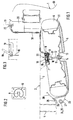
- FIG. 1 shows a lower, rear area of a trunk 2 Motor vehicle 1.
- a cover 5 On the floor 3 of the trunk 2 is in front of a rear axle 4 a cover 5 with a spare wheel 6 held therein.
- a to the rear axle 4 Behind surface 7 inclined at the bottom on the trunk floor 3.
- a lock 8 On the sloping surface 7 is a lock 8 with an opening 9 facing the roadway. Part of the opening 9 is closed by a spring 10 which is adjustable in the radial direction limited.
- a bolt 12 is fastened in the cover 5 at the level of the wheel center 11.
- the spare wheel is fixed in position 6 an annular elevation 13 is formed in the cover 5, in which the lower end 14 of the bolt 12 is attached.
- a conical tip is formed, to which a cross-sectional constriction 16 connects.
- a stop 17 is formed below the cross-sectional constriction 16 with a larger diameter. The width and depth of the cross-sectional constriction 16 is dimensioned such that the spring 10 during the locking process in the Cross-sectional constriction 16 engages.
- a cable pull 18 is arranged on the spring 10 in such a way that that the diameter of an actuating element 19 designed as a lever the spring 10 in the region of the cross-sectional constriction 16 of the bolt 12 so can be enlarged or pulled apart that the upper end 15 of the Bolt 12 is released from the locking position and the spare wheel 6 with the cover 5 down in the direction of the lane and turns around a front axis of rotation 27 rotates.
- the cable 18 is in the embodiment shown in FIG. 1 up to a recessed grip 21 formed in an end wall 20 out in which the lever 19 is pivotally mounted.
- the cover 5 at its front end 23 via a second attachment 24 to the body of the Motor vehicle held.
- the second attachment 24 is that in the figures 1 and 4 shown embodiment from two laterally spaced apart Hooks 25, 26, which are open towards the rear and each have a bolt or one grasping rod 27 serving as pivot axis. If the first attachment 22 released, the cover 5 pivots with the spare wheel 6 about the pivot axis 27 down towards the roadway.
- a securing tab 28 provided in an opening or recess 29 of a sliding surface 30 engages.
- the length and slope of the sliding surface 30 are in cooperation with the inclination of the cover 5 and the spare wheel held therein 6 designed so that when the cover 5 is moved with the spare wheel 6 in the event of a rear-end collision or the like, the spare wheel 6 on the sliding surface 30 slides down, so that the rear axle 4 by the displacement the spare wheel 6 is not damaged.
- the securing tab 28 transferable force dimensioned so that the securing tab 28th from a predetermined force shears off or moves out of the opening 29.
- the lock 8 including the spring 10 in that described above Movement direction open, so that the first attachment 22 from a predetermined force is moved from the locking position.
- Figure 2 shows an embodiment of a spring 10 open in the direction of displacement.
- FIG. 3 shows the unlocking lever or the actuating element 19 for one in a horizontal position, in which the cover 5 on the lock 8 on Trunk floor 3 is attached and the other in a pivoted upwards Position in which the cover 5 comes out of the latch with the trunk floor 3 is solved.
- the unlocking lever 19 As long as the unlocking lever 19 is up, the Tailgate cannot be closed. So closing the tailgate is only possible if the spare wheel cover 5 is locked, because then the unlocking lever 19 is horizontal again.
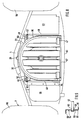
- FIG. 4 shows an embodiment of a cover 5 on the rear End 31 of the space not required for the spare wheel 6 as storage space 32 and 33 is used.
- the cover 5 consists of a Bottom 34 and a circumferential side wall 35, which in the shown in Figure 4 Embodiment at the rear end 31 a recess 36 for easier Handling.
- the cover 5 is essentially U-shaped.
- the side wall 35 has in the area of rear end 31 additional, circular wall sections 37, 38, the Radius are adapted to the diameter of the spare wheel 6.
- the storage space 32 is provided with a cover 39, which for example is arranged on the side wall 35 about a pivot axis 40.
- a locking device 41 for example consists of a rotatable hook, which by a corresponding on the side wall 35 trained counterpart can be locked.
- the storage space 33 of the figure 6 is divided into two compartments 43, 44 by an intermediate wall 42.
- Drain holes 45 are also formed, through which the cover 5 accumulating water can drain off.
- a projecting pin or pin 46 is formed on both sides.
- FIG. 7 shows an embodiment of a cover 47, which is next to the first Fastening 22 is held in guide pins 49 guided in link curves 48.
- the link pin 49 are at the front end 23 of the cover 47 on the right and formed on the left on the side walls 35.
- the side walls 35 each extending in the direction of the trunk floor 3 Have elevation 50.
- the locked is in solid lines Position of the cover 47 shown with the spare wheel 6.
- the Figure 7 in dash-dotted lines the removal position for the spare wheel 6.
- Die Cover 47 is for removal from the locked position of the first attachment 22 solved.
- the cover 47 falls down with the spare wheel 6 and is formed by the pins 46 formed on both sides in one of the trunk floor 3 spaced position caught.
- FIG. 8 shows the position of the cover 47 in front of the rear axle 4.
- the sliding plate or the sliding surface 30 for a clearer representation omitted.
- At the front end 23 of the cover 47 are on the left and right the elevations or projections 50 formed on the side walls 35, in which the link pin 49 are arranged.
- the outer ends 52 of the link pin 49 are in the backdrop curves 48.
- the right backdrop curve 48 is in the embodiment shown in Figure 8, for example in the outer wall a storage box 53 is formed.
- the left backdrop curve 48 is in one formed separate component 54. Since, in addition to component 54, an exhaust system 55 runs, the component 54 is made of a heat-resistant material, for example Made of metal.
- the storage box 53 can be made of plastic or the like consist.
- cover 47 largely lies between the vehicle wheels 56.
- the cover 47 is by at least one safety rope or one Catch rod connected to the body of the motor vehicle.
- the lower, rear Edge 57 of cover 47 is aerodynamically at vehicle boundary 51, for example, a bumper trim.
- Figure 9 shows a sectional view of the left component 54, in which the outer End 52 of the link pin 49 is guided in the link curve 48.
- the component 54 consists essentially of an L-shaped sheet, the short section 58 of the component 54 is used for fastening and wherein in the long section 59 Link curve 48 is formed.
- a horizontal section 61 is formed, which acts as a catch or stop for the pin 46 is used.
- a corresponding stop is also formed on the wall in which the right backdrop curve 48 is located.
Landscapes
- Engineering & Computer Science (AREA)
- Chemical & Material Sciences (AREA)
- Combustion & Propulsion (AREA)
- Transportation (AREA)
- Mechanical Engineering (AREA)
- Body Structure For Vehicles (AREA)
Abstract
Description
Die Erfindung betrifft eine Anordnung eines Reserverades an einem Kraftfahrzeug gemäß dem Oberbegriff des Anspruchs 1.The invention relates to an arrangement of a spare wheel on a motor vehicle according to the preamble of claim 1.
Aus der DE-AS 26 21 922 ist bereits eine Anordnung eines Reserverades an einem Kraftfahrzeug bekannt, wobei das Reserverad unter dem Kofferraumboden am Heck des Kraftfahrzeuges befestigt ist. Das Reserverad liegt in einem offenen Korb. Der Korb ist an seinem dem Fahrzeugende zugewandten Ende über eine Verriegelungseinrichtung am Fahrzeugboden angehängt. Das dazu gegenüberliegende vordere Ende des Korbes ist um eine Querachse am unteren Ende zweier Schwingen schwenkbar gelagert. Die Schwingen sind ihrerseits mit ihrem oberen Ende an einer gemeinsamen Querachse gelagert, die relativ zur unteren Querachse zur Fahrzeugmitte hin versetzt ist. Aufgrund dieser Anordnung ist der Korb und damit das darin liegende Reserverad in Fahrtrichtung nach vorne hin schräg nach unten geneigt. Die Schwingen sind an ihrem oberen Ende jeweils zusätzlich zu der Drehachse mit einer Niete befestigt, wobei diese Nieten unter einer vorbestimmten Kraft abscheren. Wirkt auf das Fahrzeug ein kräftiger Stoß auf das Heck ein und werden die den Kofferraum begrenzenden Bleche zusammengedrückt, dann wird das Reserverad nach vorne geschoben und die Schwingen werden aufgrund ihrer Ausrichtung nach dem Abscheren der Nieten um die Drehachse nach unten und nach vorne verschwenkt. Bei einem voll eingedrückten Fahrzeugheck kommt das Reserverad unter einem vor der Hinterachse angeordneten Fahrzeugtank zum Liegen. Nachteilig bei dieser bekannten Anordnung ist, daß das Reserverad ungeschützt ist, wodurch es zu einer Verschmutzung und einer Beschädigung des Reserverades kommen kann.From DE-AS 26 21 922 an arrangement of a spare wheel is already on a motor vehicle known, the spare wheel under the trunk floor is attached to the rear of the motor vehicle. The spare wheel is in an open one Basket. The basket is at its end facing the vehicle end over a Locking device attached to the vehicle floor. The opposite the front end of the basket is about a transverse axis at the lower end of two Swing is pivotally mounted. The wings are in turn with their upper one End mounted on a common transverse axis that is relative to the lower transverse axis is shifted towards the center of the vehicle. Because of this arrangement, the basket is and thus the spare wheel in it is inclined towards the front in the direction of travel tilted down. The wings are additional at their upper ends attached to the axis of rotation with a rivet, these rivets under a predetermined Shear off force. Has a powerful impact on the rear of the vehicle and the sheets that delimit the trunk are pressed together, then the spare wheel is pushed forward and the wings are due their orientation after the rivets have sheared around the axis of rotation pivoted down and forward. When the rear of the vehicle is fully depressed the spare wheel comes under a vehicle tank located in front of the rear axle to lie down. A disadvantage of this known arrangement is that the spare wheel is unprotected, causing pollution and damage of the spare wheel can come.
Aufgabe der Erfindung ist es, eine Anordnung eines Reserverades an einem Kraftfahrzeug zu schaffen, durch die eine Beschädigung der Hinterachse bei einer Krafteinwirkung auf das Fahrzeugheck vermieden ist und bei der gleichzeitig das Reserverad vor Verschmutzung oder Beschädigung geschützt ist.The object of the invention is an arrangement of a spare wheel on a To create motor vehicle through damage to the rear axle at a Force on the rear of the vehicle is avoided and at the same time that Spare wheel is protected from dirt or damage.
Diese Aufgabe wird durch die Merkmale des Anspruchs 1 gelöst.This object is solved by the features of claim 1.
Bei der erfindungsgemäßen Anordnung befindet sich das Reserverad in einer zur Straße hin geschlossenen Abdeckung. Dadurch ist das Reserverad vor einer Beschädigung und vor Verschmutzung geschützt. Die erfindungsgemäße Abdeckung ist so angeordnet und gestaltet, daß die Aerodynamik am Fahrzeugboden verbessert ist. Neben dem Reserverad kann in der erfindungsgemäßen Abdeckung ein zusätzlicher Stauraum ausgebildet sein.In the arrangement according to the invention, the spare wheel is in a Road covered cover. This prevents the spare wheel from being damaged and protected from pollution. The cover according to the invention is arranged and designed so that the aerodynamics on the vehicle floor are improved is. In addition to the spare wheel in the cover according to the invention an additional storage space can be formed.
Die Abdeckung ist an ihrem vorderen Ende nach unten geneigt und so gegenüber einer schrägen Abgleitfläche angeordnet, daß bei einer entsprechend hohen Krafteinwirkung auf das Fahrzeugheck und einer dadurch bewirkten Loslösung der Abdeckung aus ihrer Befestigung das Reserverad mit der Abdeckung an der Abgleitfläche nach vorne und nach unten gleitet. Dadurch wird eine Beschädigung der Hinterachse bei einer auf das Fahrzeugheck einwirkenden Kraft vermieden, wodurch auch die Reparaturkosten niedriger sind.The cover is inclined downward at its front end and so opposite arranged an oblique sliding surface that at a correspondingly high Force acting on the rear of the vehicle and a detachment caused thereby Cover from its attachment the spare wheel with the cover on the sliding surface slides forward and down. This will damage the Avoided rear axle with a force acting on the rear of the vehicle, whereby repair costs are also lower.
In einer vorteilhaften Ausführungsform ist am vorderen Ende der Abdeckung mindestens ein nach hinten offener hakenförmiger Halter angeformt, der unterhalb der Abgleitfläche an einer dafür vorgesehenen Drehachse eingehängt ist. Ferner ist an der Abdeckung mindestens eine nach vorne ausgerichtete Sicherungslasche vorgesehen, die in Höhe der Hinterachse mit ihrem vorderen Ende beispielsweise in eine in der Abgleitfläche ausgebildeten Öffnung eingreift. Die Sicherungslasche ist so ausgelegt, daß die Sicherungslasche ab einer vorbestimmten, auf das Fahrzeugheck einwirkenden Kraft abschert oder aus der Öffnung gelangt. Damit wird die Sicherung der Abdeckung mit dem Reserverad in bezug auf die Karosserie aufgehoben und die Abdeckung kann mit dem Reserverad an der Abgleitfläche nach vorne und unten gleiten.In an advantageous embodiment, at least the front end of the cover a hook-shaped holder open at the back is formed, which is below the Sliding surface is attached to a designated axis of rotation. Furthermore is on the cover is provided with at least one securing tab oriented towards the front, for example, at the height of the rear axle with its front end engages an opening formed in the sliding surface. The securing tab is designed so that the securing tab from a predetermined, on the vehicle rear acting force shears off or comes out of the opening. So that will securing the cover with the spare wheel in relation to the body lifted and the cover can be attached to the spare wheel on the sliding surface slide forward and down.
Die Außenwände der erfindungsgemäßen Abdeckung verlaufen in der Draufsicht im wesentlichen U-förmig. Das hintere Ende der Abdeckung ist in einer Ausführungsform offen ausgebildet. In einer weiteren vorteilhaften Ausführungsform sind am hinteren Ende der Abdeckung zusätzliche Wände angeformt, die mit den Außenwänden Hohlräume bzw. Stauräume bilden.The outer walls of the cover according to the invention run in plan view essentially U-shaped. The rear end of the cover is in one embodiment openly trained. In a further advantageous embodiment additional walls are formed at the rear end of the cover, which are connected to the Form cavities or storage spaces on the outer walls.
In einer vorteilhaften Ausführungsform erfolgt die Befestigung der Abdeckung mit dem darin befindlichen Reserverad dadurch, daß an der Abdeckung ein Bolzen in Höhe der Radmitte angeordnet ist, der durch eine in der Radfelge ausgebildete Öffnung hindurchgeht und mit seinem oberen Ende in ein am Fahrzeugboden ausgebildetes Schloß einrastet. Das Schloß weist eine in ihrem Durchmesser veränderbare Feder auf, die beim Eindringen des oberen Endes des Bolzens radial nach außen bewegt wird und danach in einer Verriegelungsstellung hinter dem Bolzenende einrastet. Diese Feder ist beispielsweise über einen Seilzug vom Fahrzeuginnenraum oder von einer geeigneten Stelle in oder am Kofferraum über ein Betätigungselement entriegelbar. Dies hat den Vorteil, daß das Reserverad auch bei einem vollen Gepäckraum und ohne Werkzeug entriegelbar ist. Vorteilhafterweise ist in dem Entriegelungsmechanismus eine Sperrstellung vorgesehen, durch die der Fahrzeugbenutzer gezwungen ist, die Reserveradabdeckung wieder in den verriegelten Zustand zu bringen. Eine vorteilhafte Möglichkeit besteht darin, daß das Betätigungselement nach dem Entriegelungsvorgang das Schließen der Heckklappe verhindert bzw. daß das Schließen der Heckklappe erfordert, daß die Reserveradabdeckung verriegelt ist.In an advantageous embodiment, the cover is attached with the spare wheel located in that a bolt on the cover in Height of the center of the wheel is arranged by a formed in the wheel rim Opening passes and with its upper end in a formed on the vehicle floor Lock engages. The lock has a diameter that can be changed Spring on radially after penetration of the upper end of the bolt is moved outside and then in a locking position behind the bolt end snaps into place. This spring is, for example, via a cable pull from the vehicle interior or from a suitable location in or on the trunk via an actuating element unlockable. This has the advantage that the spare wheel also a full luggage compartment can be unlocked without tools. Advantageously a locking position is provided in the unlocking mechanism, through which the vehicle user is forced to put the spare wheel cover back in the bring locked state. An advantageous possibility is that the actuator after the unlocking the closing of the Tailgate prevents or that closing the tailgate requires that the Spare wheel cover is locked.
In einer weiteren vorteilhaften Ausführungsform ist die Reserveradabdeckung in mindestens einer Kulisse geführt. Nach dem Lösen der Reserveradabdeckung aus der Befestigung klappt die Abdeckung mit dem Reserverad mit ihrem hinteren Ende nach unten und rutscht dann entsprechend der Kulissenbahn in Richtung des heckseitigen Endes des Kraftfahrzeuges. Die Kulissenführung ist so gestaltet, daß das Reserverad dann entnommen werden kann. Bei einer entsprechenden Ausbildung der Kulissenkurve kann die Abdeckung mit dem Reserverad unter Ausnutzung des Eigengewichtes ohne großen Kraftaufwand in die Ausgangsposition zurückgeführt werden.In a further advantageous embodiment, the spare wheel cover is in performed at least one backdrop. After removing the spare wheel cover the cover with the spare wheel works with its rear End down and then slide according to the backdrop in the direction of the rear end of the motor vehicle. The backdrop is designed so that the spare wheel can then be removed. With appropriate training The backdrop curve can take advantage of the cover with the spare wheel the dead weight without much effort in the starting position to be led back.
Ausführungsformen der Erfindung werden nachstehend anhand der Zeichnungen beispielshalber beschrieben. Dabei zeigen:
- Figur 1
- eine Schnittansicht von der Seite einer Anordnung eines Reserverades unter dem Boden eines Kofferraumes, wobei der Kofferraum nur teilweise dargestellt ist,
- Figur 2
- eine Ansicht von oben auf eine Verriegelungsfeder,
- Figur 3
- eine Teilansicht von der Seite auf einen Entriegelungshebel in einer Öffnungs- und in einer Schließstellung,
Figur 4- eine perspektivische Ansicht einer Abdeckung,
Figuren 5 und 6- perspektivische Ansichten jeweils eine Stauraumes für die Abdeckung
der
Figur 4, - Figur 7
- eine Schnittansicht von der Seite einer durch Kulissen geführten Abdeckung, wobei die Figur 7 sowohl die eingehängte Lage als auch die ausgehängte Lage der Abdeckung zeigt,
Figur 8- eine teilweise geschnittene Ansicht von oben, aus der die Abdeckung vor einer Hinterachse eines Kraftfahrzeuges ersichtlich ist, und
Figur 9- eine Schnittdarstellung eines Bauteils, bei dem in einer Kulissenkurve ein Kulissenzapfen geführt ist.
- Figure 1
- 2 shows a sectional view from the side of an arrangement of a spare wheel under the floor of a trunk, the trunk being only partially shown,
- Figure 2
- a top view of a locking spring,
- Figure 3
- a partial view from the side of an unlocking lever in an open and in a closed position,
- Figure 4
- a perspective view of a cover,
- Figures 5 and 6
- perspective views each a storage space for the cover of Figure 4,
- Figure 7
- 2 shows a sectional view from the side of a cover guided through the backdrop, FIG. 7 showing both the suspended position and the removed position of the cover,
- Figure 8
- a partially sectioned view from above, from which the cover can be seen in front of a rear axle of a motor vehicle, and
- Figure 9
- a sectional view of a component in which a link pin is guided in a link curve.
Die Figur 1 zeigt einen unteren, hinteren Bereich eines Kofferraumes 2 eines
Kraftfahrzeuges 1. Am Boden 3 des Kofferraumes 2 ist vor einer Hinterachse 4
eine Abdeckung 5 mit einem darin gehalterten Reserverad 6 befestigt. Zu diesem
Zweck ist in Richtung zur Fahrbahn eine vorstehende, zur Hinterachse 4 nach
unten geneigte Fläche 7 am Kofferraumboden 3 ausgebildet. An der schrägen Fläche
7 ist ein Schloß 8 mit einer zur Fahrbahn hin zeigenden Öffnung 9 angeordnet.
Ein Teil der Öffnung 9 wird durch eine in radialer Richtung verstellbare Feder 10
begrenzt. In der Abdeckung 5 ist in Höhe der Radmitte 11 ein Bolzen 12 befestigt.
In der in der Figur 1 gezeigten Ausführungsform ist zur Lagefixierung des Reserverades
6 eine ringförmige Erhebung 13 in der Abdeckung 5 ausgebildet, in der
das untere Ende 14 des Bolzens 12 befestigt ist. Am oberen Ende 15 des Bolzens
12 ist eine konische Spitze angeformt, an die sich eine Querschnittsverengung 16
anschließt. Unterhalb der Querschnittsverengung 16 ist ein Anschlag 17 mit einem
größeren Durchmesser ausgebildet. Die Breite und Tiefe der Querschnittsverengung
16 ist so bemessen, daß die Feder 10 beim Verriegelungsvorgang in der
Querschnittsverengung 16 einrastet. An der Feder 10 ist ein Seilzug 18 so angeordnet,
daß über ein als Hebel ausgebildetes Betätigungselement 19 der Durchmesser
der Feder 10 im Bereich der Querschnittsverengung 16 des Bolzens 12 so
vergrößert bzw. auseinandergezogen werden kann, daß das obere Ende 15 des
Bolzens 12 aus der Verriegelungsposition freigegeben wird und das Reserverad 6
mit der Abdeckung 5 nach unten in Richtung zur Fahrbahn fällt und sich dabei um
eine vordere Drehachse 27 dreht. Der Seilzug 18 ist in der Figur 1 gezeigten Ausführungsform
bis zu einer in einer Abschlußwand 20 ausgebildeten Griffmulde 21
geführt, in der der Hebel 19 schwenkbar gelagert ist.FIG. 1 shows a lower, rear area of a trunk 2
Motor vehicle 1. On the floor 3 of the trunk 2 is in front of a rear axle 4
a
Zusätzlich zu der oben beschriebenen ersten Befestigung 22 ist die Abdeckung 5
an ihrem vorderen Ende 23 über eine zweite Befestigung 24 an der Karosserie des
Kraftfahrzeuges gehaltert. Die zweite Befestigung 24 besteht in der in den Figuren
1 und 4 gezeigten Ausführungsform aus zwei seitlich voneinander beabstandeten
Haken 25, 26, die nach hinten hin offen sind und die jeweils eine Bolzen oder eine
als Schwenkachse dienende Stange 27 umgreifen. Wird die erste Befestigung 22
gelöst, schwenkt die Abdeckung 5 mit dem Reserverad 6 um die Schwenkachse 27
nach unten in Richtung zur Fahrbahn. In Richtung zur Hinterachse 4 ist eine Sicherungslasche
28 vorgesehen, die in eine Öffnung oder Aussparung 29 einer Abgleitfläche
30 eingreift. Die Länge und Schräge der Abgleitfläche 30 ist in Zusammenwirkung
mit der Neigung der Abdeckung 5 und des darin gehalterten Reserverades
6 so ausgelegt, daß bei einer Verschiebung der Abdeckung 5 mit dem Reserverad
6 bei einem Heckaufprall oder dergleichen das Reserverad 6 an der Abgleitfläche
30 nach unten rutscht, so daß die Hinterachse 4 durch die Verschiebung
des Reserverades 6 nicht beschädigt wird. Gleichzeitig ist die durch die Sicherungslasche
28 übertragbare Kraft so bemessen, daß die Sicherungslasche 28
ab einer vorbestimmten Kraft abschert oder sich aus der Öffnung 29 herausbewegt.
Darüber hinaus ist das Schloß 8 einschließlich der Feder 10 in der oben beschriebenen
Verschieberichtung offen, so daß sich die erste Befestigung 22 ab
einer vorbestimmten Kraft aus der Verriegelungsstellung bewegt. Die Figur 2 zeigt
eine Ausführungsform einer in Verschieberichtung offenen Feder 10.In addition to the
Die Figur 3 zeigt den Entriegelungshebel bzw. das Betätigungselement 19 zum
einen in einer waagrechten Stellung, in der die Abdeckung 5 über das Schloß 8 am
Kofferraum-Boden 3 befestigt ist und zum anderen in einer nach oben verschwenkten
Position, in der die Abdeckung 5 aus der Verriegelung mit dem Kofferraum-Boden
3 gelöst ist. Solange der Entriegelungshebel 19 nach oben steht, kann die
Heckklappe nicht geschlossen werden. Somit ist ein Schließen der Heckklappe nur
möglich, wenn die Reserveradabdeckung 5 verriegelt ist, weil dann der Entriegelungshebel
19 wieder waagrecht liegt.FIG. 3 shows the unlocking lever or the
In der Figur 4 ist eine Ausführungsform einer Abdeckung 5 gezeigt, an deren hinteren
Ende 31 der nicht für das Reserverad 6 benötigte Raum als Stauraum 32 und
33 genutzt ist. Wie aus der Figur 4 hervorgeht, besteht die Abdeckung 5 aus einem
Boden 34 und einer umlaufenden Seitenwand 35, die in der in der Figur 4 gezeigten
Ausführungsform am hinteren Ende 31 eine Aussparung 36 zur leichteren
Handhabung aufweist. Die Abdeckung 5 ist im wesentlichen U-förmig ausgebildet.
Zur Bildung der Stauräume 32 und 33 weist die Seitenwand 35 im Bereich des
hinteren Endes 31 zusätzliche, kreisförmige Wandabschnitte 37, 38 auf, deren
Radius dem Durchmesser des Reserverades 6 angepaßt sind.FIG. 4 shows an embodiment of a
In der Figur 5 ist der Stauraum 32 mit einem Deckel 39 versehen, der beispielsweise
um eine Schwenkachse 40 an der Seitenwand 35 angeordnet ist. Der
Deckel 39 ist mit einer Verriegelungseinrichtung 41 versehen, die beispielsweise
aus einem drehbaren Haken besteht, der durch ein entsprechendes an der Seitenwand
35 ausgebildetes Gegenstück verriegelbar ist. Der Stauraum 33 der Figur
6 ist durch eine Zwischenwand 42 in zwei Teilfächer 43, 44 unterteilt. Am Boden 34
sind ferner Ablauflöcher 45 ausgebildet, durch die sich das in der Abdeckung 5
ansammelnde Wasser abfließen kann. An den hinteren, seitlichen Außenwänden
35 ist jeweils auf beiden Seiten ein vorstehender Bolzen oder Zapfen 46 ausgebildet.
Beim Lösen der ersten Befestigung 22 fällt die Abdeckung 5 mit dem Reserverad
6 mit ihrem hinteren Ende 31 nach unten. Nach einer vorbestimmten Wegstrecke
werden die Zapfen 46 durch an der Karosserie ausgebildete Anschläge
aufgefangen.In FIG. 5, the
Die Figur 7 zeigt eine Ausführungsform einer Abdeckung 47, die neben der ersten
Befestigung 22 über in Kulissenkurven 48 geführte Kulissenzapfen 49 gehaltert ist.
Die Kulissenzapfen 49 sind am vorderen Ende 23 der Abdeckung 47 rechts und
links an den Seitenwänden 35 ausgebildet. Zu diesem Zweck können die Seitenwände
35 jeweils eine sich in Richtung des Kofferraumbodens 3 erstreckende
Erhebung 50 aufweisen. In der Figur 7 ist in durchgezogenen Linien die verriegelte
Position der Abdeckung 47 mit dem Reserverad 6 dargestellt. Zusätzlich zeigt die
Figur 7 in strichpunktierten Linien die Entnahmeposition für das Reserverad 6. Die
Abdeckung 47 wird zur Entnahme aus der Verriegelungsstellung der ersten Befestigung
22 gelöst. Die Abdeckung 47 fällt mit dem Reserverad 6 nach unten und
wird durch die beidseitig ausgebildeten Zapfen 46 in einer vom Kofferraumboden 3
beabstandeten Lage aufgefangen. Anschließend muß der Benutzer das Reserverad
6 mit der Abdeckung 47 nach hinten und nach außen ziehen. Dabei rutscht die
Abdeckung 47 mit dem Reserverad 6 entlang der jeweiligen Kulissenkurve 48 nach
unten und nach hinten, bis die Kulissenzapfen 49 zu Anschlägen an den Enden
der Kulissenkurven 48 gelangen. In dieser Lage ragt das Reserverad 6 und die
Abdeckung 47 beispielsweise zur Hälfte über die Fahrzeugbegrenzung 51 hinaus.
Das Reserverad 6 kann nun entnommen werden.FIG. 7 shows an embodiment of a
Die Figur 8 zeigt die Lage der Abdeckung 47 vor der Hinterachse 4. In der Figur 8
ist das Abgleitblech bzw. die Abgleitfläche 30 zur übersichtlicheren Darstellung
weggelassen. Am vorderen Ende 23 der Abdeckung 47 sind die links und rechts an
den Seitenwänden 35 ausgebildeten Erhebungen oder Ansätze 50 erkennbar, in
denen die Kulissenzapfen 49 angeordnet sind. Die äußeren Enden 52 der Kulissenzapfen
49 befinden sich in den Kulissenkurven 48. Die rechte Kulissenkurve 48
ist in der in der Figur 8 gezeigten Ausführungsform beispielsweise in der Außenwand
eines Ablagekastens 53 ausgebildet. Die linke Kulissenkurve 48 ist in einem
separaten Bauteil 54 ausgeformt. Da neben dem Bauteil 54 eine Abgasanlage 55
verläuft, ist das Bauteil 54 aus einem hitzebeständigen Material, beispielsweise aus
Metall hergestellt. Der Ablagekasten 53 kann hingegen aus Kunststoff oder dergleichen
bestehen. Aus der Figur 8 geht ferner hervor, daß die Abdeckung 47 weitestgehend
zwischen den Fahrzeugrädern 56 liegt. Bei einem Lösen der Abdeckung
47 infolge einer auf das Fahrzeugheck wirkenden Kraft, beispielsweise
bei einem Heck-Crash, wird durch die beiden Fahrzeugräder 56 sichergestellt, daß
die Abdeckung 47 mit dem Reserverad 6 unterhalb dem Boden 3 des Fahrzeuges
1 bleibt. Zusätzlich ist die Abdeckung 47 durch mindestens ein Fangseil oder eine
Fangstange mit der Karosserie des Kraftfahrzeuges verbunden. Die untere, hintere
Kante 57 der Abdeckung 47 ist aerodynamisch an die Fahrzeugbegrenzung 51,
beispielsweise eine Stoßfängerverkleidung, angepaßt.FIG. 8 shows the position of the
Die Figur 9 zeigt eine Schnittdarstellung des linken Bauteils 54, in der das äußere
Ende 52 des Kulissenzapfens 49 in der Kulissenkurve 48 geführt ist. Das Bauteil
54 besteht im wesentlichen aus einem L-förmigen Blech, wobei der kurze Abschnitt
58 des Bauteils 54 zur Befestigung dient und wobei in dem langen Abschnitt 59 die
Kulissenkurve 48 ausgebildet ist. Am unteren Ende 60 des langen Abschnitts 59
des Bauteils 54 ist ein waagrechter Abschnitt 61 ausgebildet, der als Fangnase
oder Anschlag für den Zapfen 46 dient. Ein entsprechender Anschlag ist ebenfalls
an der Wand ausgebildet, in der sich die rechte Kulissenkurve 48 befindet.Figure 9 shows a sectional view of the
Claims (9)
Applications Claiming Priority (2)
| Application Number | Priority Date | Filing Date | Title |
|---|---|---|---|
| DE19626533A DE19626533A1 (en) | 1996-07-02 | 1996-07-02 | Arrangement of a spare wheel on a motor vehicle |
| DE19626533 | 1996-07-02 |
Publications (2)
| Publication Number | Publication Date |
|---|---|
| EP0816209A1 true EP0816209A1 (en) | 1998-01-07 |
| EP0816209B1 EP0816209B1 (en) | 2000-03-15 |
Family
ID=7798663
Family Applications (1)
| Application Number | Title | Priority Date | Filing Date |
|---|---|---|---|
| EP97110692A Expired - Lifetime EP0816209B1 (en) | 1996-07-02 | 1997-07-01 | Arrangement of a spare wheel of a motor vehicle |
Country Status (3)
| Country | Link |
|---|---|
| EP (1) | EP0816209B1 (en) |
| DE (2) | DE19626533A1 (en) |
| ES (1) | ES2145537T3 (en) |
Cited By (3)
| Publication number | Priority date | Publication date | Assignee | Title |
|---|---|---|---|---|
| FR2806361A1 (en) * | 2000-03-20 | 2001-09-21 | Plastic Omnium Cie | DRAWER FOR MOTOR VEHICLE, CLOSED AT THE REAR BY A FACADE FORMING A BODY ELEMENT |
| FR2870199A1 (en) * | 2004-05-17 | 2005-11-18 | Renault Sas | ARRANGEMENT FOR EMERGENCY WHEEL OF A MOTOR VEHICLE |
| FR2924671A3 (en) * | 2007-12-05 | 2009-06-12 | Renault Sas | Spare wheel withdrawing and positioning basket for motor vehicle, has thermal screen mounted at periphery of basket shaped main body and guiding spare wheel during insertion of spare wheel in basket |
Families Citing this family (3)
| Publication number | Priority date | Publication date | Assignee | Title |
|---|---|---|---|---|
| DE19852770C1 (en) * | 1998-11-16 | 2000-05-25 | Bayerische Motoren Werke Ag | Spare wheel mounting for motor vehicle has lowerable support for wheel with lever and actuator |
| DE19904551A1 (en) * | 1999-02-04 | 2000-08-10 | Bayerische Motoren Werke Ag | Holder for spare wheel, for motor vehicles consists of two-part wheel basket, with one part sliding out via guide for easy access |
| DE102011016516A1 (en) * | 2011-04-08 | 2012-10-11 | Burg Silvergreen Gmbh | Device for locking spare wheel, has carrier, on which side wall of spare wheel rests in locked state, while engagement unit communicates with another side wall of spare wheel, and flexible clamping element is guided through center opening |
Citations (6)
| Publication number | Priority date | Publication date | Assignee | Title |
|---|---|---|---|---|
| FR1475761A (en) * | 1966-01-29 | 1967-04-07 | Spare wheel holder for motor vehicles | |
| US3369683A (en) * | 1966-06-06 | 1968-02-20 | Wallace E J | Spare wheel carriers |
| DE2045630A1 (en) * | 1969-11-24 | 1971-06-16 | Automobiles Peugeot, Paris, Regie Nationale des Usines Renault, Billan court, (Frankreich) | Arrangement of the fuel tank and a spare wheel in a motor vehicle |
| EP0477095A1 (en) * | 1990-09-18 | 1992-03-25 | Garage Issele S.A. | Storage device for a spare wheel |
| DE4304180A1 (en) * | 1992-02-25 | 1993-08-26 | Volkswagen Ag | Engine fuel system with fuel-vapour filter - has filter housing formed by recess in fuel tank accessible from outside after removing cover |
| DE4323621C1 (en) * | 1993-07-15 | 1994-09-08 | Daimler Benz Ag | Spare wheel holder for a vehicle |
Family Cites Families (5)
| Publication number | Priority date | Publication date | Assignee | Title |
|---|---|---|---|---|
| DE1257607B (en) * | 1961-12-13 | 1967-12-28 | Renault | Holding device for a spare wheel on motor vehicles |
| US3682360A (en) * | 1970-10-28 | 1972-08-08 | Earl B Fletcher | Bumper and spare tire assembly |
| FR2317152A1 (en) * | 1975-07-07 | 1977-02-04 | Peugeot | DEVICE FOR STORING A SPARE WHEEL ON A MOTOR VEHICLE |
| DE3042910A1 (en) * | 1980-11-14 | 1982-07-01 | Daimler-Benz Ag, 7000 Stuttgart | SPARE WHEEL CARRIER FOR MOTOR VEHICLES |
| US4805817A (en) * | 1986-10-17 | 1989-02-21 | Helterbrand David L | Locking bar for use with a spare tire carrier |
-
1996
- 1996-07-02 DE DE19626533A patent/DE19626533A1/en not_active Withdrawn
-
1997
- 1997-07-01 ES ES97110692T patent/ES2145537T3/en not_active Expired - Lifetime
- 1997-07-01 DE DE59701250T patent/DE59701250D1/en not_active Expired - Lifetime
- 1997-07-01 EP EP97110692A patent/EP0816209B1/en not_active Expired - Lifetime
Patent Citations (6)
| Publication number | Priority date | Publication date | Assignee | Title |
|---|---|---|---|---|
| FR1475761A (en) * | 1966-01-29 | 1967-04-07 | Spare wheel holder for motor vehicles | |
| US3369683A (en) * | 1966-06-06 | 1968-02-20 | Wallace E J | Spare wheel carriers |
| DE2045630A1 (en) * | 1969-11-24 | 1971-06-16 | Automobiles Peugeot, Paris, Regie Nationale des Usines Renault, Billan court, (Frankreich) | Arrangement of the fuel tank and a spare wheel in a motor vehicle |
| EP0477095A1 (en) * | 1990-09-18 | 1992-03-25 | Garage Issele S.A. | Storage device for a spare wheel |
| DE4304180A1 (en) * | 1992-02-25 | 1993-08-26 | Volkswagen Ag | Engine fuel system with fuel-vapour filter - has filter housing formed by recess in fuel tank accessible from outside after removing cover |
| DE4323621C1 (en) * | 1993-07-15 | 1994-09-08 | Daimler Benz Ag | Spare wheel holder for a vehicle |
Cited By (8)
| Publication number | Priority date | Publication date | Assignee | Title |
|---|---|---|---|---|
| FR2806361A1 (en) * | 2000-03-20 | 2001-09-21 | Plastic Omnium Cie | DRAWER FOR MOTOR VEHICLE, CLOSED AT THE REAR BY A FACADE FORMING A BODY ELEMENT |
| EP1136321A1 (en) * | 2000-03-20 | 2001-09-26 | Compagnie Plastic Omnium | Vehicle storage compartment, closed at its end by a bodywork element |
| US6659525B2 (en) | 2000-03-20 | 2003-12-09 | Compagnie Plastic Omnium | Motor vehicle storage module closed at the rear by a facade forming an element of bodywork |
| FR2870199A1 (en) * | 2004-05-17 | 2005-11-18 | Renault Sas | ARRANGEMENT FOR EMERGENCY WHEEL OF A MOTOR VEHICLE |
| WO2005113319A1 (en) * | 2004-05-17 | 2005-12-01 | Renault S.A.S. | Arrangement for a spare wheel in a motor vehicle |
| JP2007537922A (en) * | 2004-05-17 | 2007-12-27 | ルノー、エス、ア、エス | Spare tire placement in automobiles |
| JP4708425B2 (en) * | 2004-05-17 | 2011-06-22 | ルノー・エス・アー・エス | Spare tire placement in automobiles |
| FR2924671A3 (en) * | 2007-12-05 | 2009-06-12 | Renault Sas | Spare wheel withdrawing and positioning basket for motor vehicle, has thermal screen mounted at periphery of basket shaped main body and guiding spare wheel during insertion of spare wheel in basket |
Also Published As
| Publication number | Publication date |
|---|---|
| EP0816209B1 (en) | 2000-03-15 |
| ES2145537T3 (en) | 2000-07-01 |
| DE59701250D1 (en) | 2000-04-20 |
| DE19626533A1 (en) | 1998-01-08 |
Similar Documents
| Publication | Publication Date | Title |
|---|---|---|
| DE69829343T2 (en) | Fastening device of a vehicle panel | |
| DE69916923T2 (en) | On the rail floor built rack device | |
| DE102018107750A1 (en) | LOADING LAYERS AND LATCHING ARRANGEMENTS, AND VEHICLES THEREOF | |
| DE2437757B2 (en) | Protective cover for a dashboard of vehicles | |
| DE102019105830A1 (en) | DOUBLE-TRAIL LOCKING ARRANGEMENTS FOR PROFESSIONAL CLOSURES OF MOTOR VEHICLES | |
| DE4225670C2 (en) | Rotary latch lock with catch hook | |
| DE202015007818U1 (en) | Suspension arrangement for a vehicle door of a vehicle, vehicle door which is suspended by means of a suspension assembly to a vehicle and vehicle with a vehicle door, which is hung with such a suspension arrangement on the vehicle | |
| EP0816209B1 (en) | Arrangement of a spare wheel of a motor vehicle | |
| DE60110526T2 (en) | Vehicle body front structure for automobiles | |
| DE102009007134A1 (en) | Trailer for a children's vehicle | |
| EP1794038A1 (en) | Security device for a motor vehicle | |
| DE2159749C3 (en) | Lock for movable body paneling parts on motor vehicles, such as engine hoods and trunk lids | |
| DE102005023831A1 (en) | Automotive hood locking mechanism has lock fittings located either side of the hood mid-line astride energy-absorbent zone | |
| DE4305248C2 (en) | Adjustment device on a flap | |
| EP2054254B1 (en) | Motor vehicle with a luggage space | |
| EP0783906B1 (en) | Children's toy | |
| EP1405764B1 (en) | Load carrier, particularly a bicycle carrier | |
| DE20313924U1 (en) | Hinge assembly for a vehicle motor compartment hood, with a base and an upper section with a joint, has a lock at the link member between them to be disengaged on an impact collision to allow the hood to lift | |
| DE4033622C2 (en) | Trunk lid for a motor vehicle | |
| EP0093795B1 (en) | Hitch for motor vehicle | |
| EP3750772B1 (en) | Coupling head, especially for a rail vehicle | |
| DE102005007122B4 (en) | Motor vehicle seat with folding backrest | |
| DE10056083B4 (en) | Device for unlocking and locking | |
| DE19522353A1 (en) | Convertible roof stowage compartment lid | |
| DE102010021897A1 (en) | Connecting rod flap arrangement for cabriolet, has pivoted and linearly movable flap for locking and releasing connecting rod opening |
Legal Events
| Date | Code | Title | Description |
|---|---|---|---|
| PUAI | Public reference made under article 153(3) epc to a published international application that has entered the european phase |
Free format text: ORIGINAL CODE: 0009012 |
|
| AK | Designated contracting states |
Kind code of ref document: A1 Designated state(s): DE ES FR GB IT |
|
| 17P | Request for examination filed |
Effective date: 19980206 |
|
| AKX | Designation fees paid |
Free format text: DE ES FR GB IT |
|
| RBV | Designated contracting states (corrected) |
Designated state(s): DE ES FR GB IT |
|
| 17Q | First examination report despatched |
Effective date: 19990505 |
|
| GRAG | Despatch of communication of intention to grant |
Free format text: ORIGINAL CODE: EPIDOS AGRA |
|
| GRAG | Despatch of communication of intention to grant |
Free format text: ORIGINAL CODE: EPIDOS AGRA |
|
| GRAH | Despatch of communication of intention to grant a patent |
Free format text: ORIGINAL CODE: EPIDOS IGRA |
|
| GRAH | Despatch of communication of intention to grant a patent |
Free format text: ORIGINAL CODE: EPIDOS IGRA |
|
| GRAA | (expected) grant |
Free format text: ORIGINAL CODE: 0009210 |
|
| AK | Designated contracting states |
Kind code of ref document: B1 Designated state(s): DE ES FR GB IT |
|
| GBT | Gb: translation of ep patent filed (gb section 77(6)(a)/1977) |
Effective date: 20000316 |
|
| REF | Corresponds to: |
Ref document number: 59701250 Country of ref document: DE Date of ref document: 20000420 |
|
| ITF | It: translation for a ep patent filed |
Owner name: STUDIO JAUMANN P. & C. S.N.C. |
|
| ET | Fr: translation filed | ||
| REG | Reference to a national code |
Ref country code: ES Ref legal event code: FG2A Ref document number: 2145537 Country of ref document: ES Kind code of ref document: T3 |
|
| PLBE | No opposition filed within time limit |
Free format text: ORIGINAL CODE: 0009261 |
|
| STAA | Information on the status of an ep patent application or granted ep patent |
Free format text: STATUS: NO OPPOSITION FILED WITHIN TIME LIMIT |
|
| 26N | No opposition filed | ||
| REG | Reference to a national code |
Ref country code: GB Ref legal event code: IF02 |
|
| PGFP | Annual fee paid to national office [announced via postgrant information from national office to epo] |
Ref country code: ES Payment date: 20140509 Year of fee payment: 18 |
|
| PGFP | Annual fee paid to national office [announced via postgrant information from national office to epo] |
Ref country code: DE Payment date: 20140725 Year of fee payment: 18 |
|
| PGFP | Annual fee paid to national office [announced via postgrant information from national office to epo] |
Ref country code: FR Payment date: 20140728 Year of fee payment: 18 Ref country code: GB Payment date: 20140731 Year of fee payment: 18 |
|
| PGFP | Annual fee paid to national office [announced via postgrant information from national office to epo] |
Ref country code: IT Payment date: 20140730 Year of fee payment: 18 |
|
| REG | Reference to a national code |
Ref country code: DE Ref legal event code: R119 Ref document number: 59701250 Country of ref document: DE |
|
| GBPC | Gb: european patent ceased through non-payment of renewal fee |
Effective date: 20150701 |
|
| PG25 | Lapsed in a contracting state [announced via postgrant information from national office to epo] |
Ref country code: GB Free format text: LAPSE BECAUSE OF NON-PAYMENT OF DUE FEES Effective date: 20150701 Ref country code: IT Free format text: LAPSE BECAUSE OF NON-PAYMENT OF DUE FEES Effective date: 20150701 Ref country code: DE Free format text: LAPSE BECAUSE OF NON-PAYMENT OF DUE FEES Effective date: 20160202 |
|
| REG | Reference to a national code |
Ref country code: FR Ref legal event code: ST Effective date: 20160331 |
|
| PG25 | Lapsed in a contracting state [announced via postgrant information from national office to epo] |
Ref country code: FR Free format text: LAPSE BECAUSE OF NON-PAYMENT OF DUE FEES Effective date: 20150731 |
|
| REG | Reference to a national code |
Ref country code: ES Ref legal event code: FD2A Effective date: 20160826 |
|
| PG25 | Lapsed in a contracting state [announced via postgrant information from national office to epo] |
Ref country code: ES Free format text: LAPSE BECAUSE OF NON-PAYMENT OF DUE FEES Effective date: 20150702 |