EP0816089A2 - Tintenstrahlaufzeichnungskopf und Tintenstrahlaufzeichnungsapparat - Google Patents
Tintenstrahlaufzeichnungskopf und Tintenstrahlaufzeichnungsapparat Download PDFInfo
- Publication number
- EP0816089A2 EP0816089A2 EP97110385A EP97110385A EP0816089A2 EP 0816089 A2 EP0816089 A2 EP 0816089A2 EP 97110385 A EP97110385 A EP 97110385A EP 97110385 A EP97110385 A EP 97110385A EP 0816089 A2 EP0816089 A2 EP 0816089A2
- Authority
- EP
- European Patent Office
- Prior art keywords
- ink
- discharge
- jet recording
- thermoelectric
- recording head
- Prior art date
- Legal status (The legal status is an assumption and is not a legal conclusion. Google has not performed a legal analysis and makes no representation as to the accuracy of the status listed.)
- Granted
Links
Images


Classifications
-
- B—PERFORMING OPERATIONS; TRANSPORTING
- B41—PRINTING; LINING MACHINES; TYPEWRITERS; STAMPS
- B41J—TYPEWRITERS; SELECTIVE PRINTING MECHANISMS, i.e. MECHANISMS PRINTING OTHERWISE THAN FROM A FORME; CORRECTION OF TYPOGRAPHICAL ERRORS
- B41J2/00—Typewriters or selective printing mechanisms characterised by the printing or marking process for which they are designed
- B41J2/005—Typewriters or selective printing mechanisms characterised by the printing or marking process for which they are designed characterised by bringing liquid or particles selectively into contact with a printing material
- B41J2/01—Ink jet
- B41J2/135—Nozzles
- B41J2/14—Structure thereof only for on-demand ink jet heads
- B41J2/14016—Structure of bubble jet print heads
- B41J2/14032—Structure of the pressure chamber
- B41J2/1404—Geometrical characteristics
-
- B—PERFORMING OPERATIONS; TRANSPORTING
- B41—PRINTING; LINING MACHINES; TYPEWRITERS; STAMPS
- B41J—TYPEWRITERS; SELECTIVE PRINTING MECHANISMS, i.e. MECHANISMS PRINTING OTHERWISE THAN FROM A FORME; CORRECTION OF TYPOGRAPHICAL ERRORS
- B41J2/00—Typewriters or selective printing mechanisms characterised by the printing or marking process for which they are designed
- B41J2/005—Typewriters or selective printing mechanisms characterised by the printing or marking process for which they are designed characterised by bringing liquid or particles selectively into contact with a printing material
- B41J2/01—Ink jet
- B41J2/135—Nozzles
- B41J2/14—Structure thereof only for on-demand ink jet heads
- B41J2/14016—Structure of bubble jet print heads
- B41J2/14032—Structure of the pressure chamber
- B41J2/14056—Plural heating elements per ink chamber
-
- B—PERFORMING OPERATIONS; TRANSPORTING
- B41—PRINTING; LINING MACHINES; TYPEWRITERS; STAMPS
- B41J—TYPEWRITERS; SELECTIVE PRINTING MECHANISMS, i.e. MECHANISMS PRINTING OTHERWISE THAN FROM A FORME; CORRECTION OF TYPOGRAPHICAL ERRORS
- B41J2/00—Typewriters or selective printing mechanisms characterised by the printing or marking process for which they are designed
- B41J2/005—Typewriters or selective printing mechanisms characterised by the printing or marking process for which they are designed characterised by bringing liquid or particles selectively into contact with a printing material
- B41J2/01—Ink jet
- B41J2/135—Nozzles
- B41J2/14—Structure thereof only for on-demand ink jet heads
- B41J2/14016—Structure of bubble jet print heads
- B41J2/14088—Structure of heating means
- B41J2/14112—Resistive element
- B41J2/14129—Layer structure
-
- B—PERFORMING OPERATIONS; TRANSPORTING
- B41—PRINTING; LINING MACHINES; TYPEWRITERS; STAMPS
- B41J—TYPEWRITERS; SELECTIVE PRINTING MECHANISMS, i.e. MECHANISMS PRINTING OTHERWISE THAN FROM A FORME; CORRECTION OF TYPOGRAPHICAL ERRORS
- B41J2202/00—Embodiments of or processes related to ink-jet or thermal heads
- B41J2202/01—Embodiments of or processes related to ink-jet heads
- B41J2202/21—Line printing
Definitions
- This invention relates to an ink-jet recording head having a plurality of thermoelectric transducers in one flow path (nozzle), and an ink-jet recording apparatus employing such a head.
- Ink-jet recording apparatus are mostly used as printing apparatus in printers, facsimile machines, word processors, copying machines and so forth.
- ink-jet recording apparatus of a system in which heat energy is used as an energy utilized for the discharge of ink and bubbles are generated by the heat energy to discharge the ink are recently coming into wide use.
- thermoelectric transducers hereinafter also “heaters”
- heads having a plurality of heads for one discharge opening from the viewpoint of the following are also known in the art.
- a head comprising a plurality of heaters which are driven alternately or one by one so that the ink-jet recording head can have a long lifetime.
- a head making use of a plurality of heaters so that the quantity of ink discharge (discharge quantity) can be changed over a broader range, where the discharge quantity is changed by selecting the heaters to be driven or the number thereof.
- the latter has, as a more specific construction, a plurality of heaters arranged in the direction of ink discharge in an ink flow path communicating with the discharge opening of the ink-jet recording head, where the heater to be driven (heat-generated) or the number of the heater are selected to make different the distance between the discharge opening and the heater(s) to be driven to thereby change the discharge quantity.
- a plurality of heaters arranged in the direction of ink discharge in an ink flow path communicating with the discharge opening of the ink-jet recording head, where the heater to be driven (heat-generated) or the number of the heater are selected to make different the distance between the discharge opening and the heater(s) to be driven to thereby change the discharge quantity.
- a head is also known in which, as disclosed, e.g., in Japanese Patent Application Laid-open No. 55-132259, a plurality of heaters having surface areas different from one another are arranged in its ink flow path, and similarly the heater to be driven or the number thereof is changed to make the discharge quantity changeable.
- the preliminary discharge is performed usually when the apparatus is in a certain specified state, and the ink not participating in the recording is discharged from the ink-jet recording head, whereby any ink having thickened in the ink-jet recording head is removed so that the ink discharge can be kept in a good state.
- Such preliminary discharge is performed at given time intervals immediately after the power source of the apparatus is turned on or in the course of recording.
- the preliminary discharge must be performed at short intervals when the recording is performed in the discharge quantity set small. More specifically, since the ink droplets with a small discharge quantity have a small power, there is a possibility that the thick ink can not be stably discharged, depending on how the ink has thickened as a result of the evaporation of water at the discharge opening. Hence, it becomes necessary to frequently perform the preliminary discharge. In particular, the preliminary discharge performed at given time intervals in the course of recording must be done at shorter intervals, bringing about the problem of a decrease in through-put of the recording.
- discharge of ink droplets at a low velocity may cause more or less a change of the direction of discharge from the discharge opening to cause a lowering of the performance of ink-shot against a recording medium, tending to adversely affect the image quality.
- the discharge velocity is substantially proportional to the discharge quantity, thus a difference in discharge velocity is great when the discharge quantity is large or small.
- the large dots and small dots formed by the ink droplets discharged in a large discharge quantity and a small discharge quantity are shot at different positions because of the difference in discharge velocity, resulting in an increase in the possibility of faulty images.
- the conventional ink-jet recording heads have the following problems.
- the recording apparatus results in spec-down if the recording in conventional discharge quantity is performed at a low speed, even though the recording in small discharge quantity can be performed at a high speed.
- ink-jet recording heads it is also important for ink-jet recording heads to be of types common to former types. This is due to, e.g., the fact that ink-jet recording heads having a stated discharge quantity are used as exchange types. If, for the purpose of improving the function of recording apparatus, an ink-jet recording head is so set up that not only ink droplets in a large discharge quantity but also those in a small discharge quantity are discharged using the same head and the head is not of the type common to former types, a former type ink-jet recording head and a new type ink-jet recording head for discharging ink droplets of large discharge quantity and small discharge quantity must be produced in parallel, bringing about problems of an increase in production lines and an increase in production cost.
- an object of the present invention is to provide an ink-jet recording head that is so set up that a plurality of heaters are provided for one discharge opening, having advantages that the head can have a long lifetime and can enjoy a broader range within which the ink discharge quantity is changeable, can perform high-speed recording of high-quality images and also can be used in former-type recording apparatus.
- the ink-jet recording head of the present invention is an ink-jet recording head comprising a plurality of liquid flow paths having discharge openings for discharging an ink, and a plurality of thermoelectric transducers provided for each liquid flow path in order to discharge the ink, wherein;
- At least one additional thermoelectric transducer may be substantially the same thermoelectric transducer as the frontward thermoelectric transducer, and this at least one additional thermoelectric transducer may have a distance OH of the second region.
- thermoelectric transducers may also be so provided that the distance from an end of the discharge opening side of each thermoelectric transducer to the discharge opening is different from that of the additional thermoelectric transducer, and are so provided that a discharge velocity vF and a discharge quantity VdF at the time when only the frontward thermoelectric transducer is used and a discharge velocity vF+B and a discharge quantity VdF+B at the time when the frontward thermoelectric transducer and the additional thermoelectric transducer are used satisfy the relation of: (vF/VdF) > (vF+B/VdF+B).
- the additional thermoelectric transducer may also be so provided that, when the ink is discharged by the additional thermoelectric transducer alone, the value of (discharge velocity v/discharge quantity Vd) with respect to the distance OH is at a distance OH of the second region in a regional classification into a first region in which the value of v/Vd increases with a decrease in the distance OH and a second region in which it comes to be substantially constant with an increase in the distance OH.
- thermoelectric transducers may form bubbles by film boiling, the thermoelectric transducers may each have a length of from 80 ⁇ m to 140 ⁇ m and a width smaller than the diameter of the discharge opening, and both the frontward thermoelectric transducer and the additional thermoelectric transducer may have a portion where they are provided adjacently in parallel; the distance OH of the frontward thermoelectric transducer being 130 ⁇ m or less.
- the ink-jet recording head of the present invention comprises a plurality of liquid flow paths having discharge openings for discharging an ink, and a plurality of thermoelectric transducers provided for each liquid flow path in order to discharge the ink, wherein;
- the discharge velocity vF and the discharge quantity VdF at the time when only a thermoelectric transducer located frontward on the discharge opening side is used and the discharge velocity vF+B and the discharge quantity VdF+B at the time when both the frontward thermoelectric transducer and the additional thermoelectric transducer are used may satisfy the relation of: vF ⁇ 8 (m/S) vF+B ⁇ 16 (m/S) VdF ⁇ 25 (pl) 35 ⁇ VdF+B ⁇ 45 (pl).
- the above ink may be a color ink having a surface tension of from about 26.0 dyne/cm to about 37.0 dyne/cm and a viscosity of from 1.85 cP to 2.60 cP.
- the discharge velocity vF and the discharge quantity VdF at the time when only a thermoelectric transducer located frontward on the discharge opening side is used and the discharge velocity vF+B and the discharge quantity VdF+B at the time when both the frontward thermoelectric transducer and the additional thermoelectric transducer are used may also satisfy the relation of: vF ⁇ 7.5 (m/S) vF+B ⁇ 16 (m/S) VdF ⁇ 40 (pl) 65 ⁇ VdF+B ⁇ 80 (pl).
- the above ink may be a black ink having a surface tension of from about 40.5 dyne/cm to about 46.5 dyne/cm and a viscosity of from 1.5 cP to 2.1 cP.
- the ink-jet recording head of the present invention comprises a plurality of liquid flow paths having discharge openings for discharging an ink, and a plurality of thermoelectric transducers provided for each liquid flow path in order to discharge the ink, wherein;
- the rearward thermoelectric transducer may be larger than the frontward thermoelectric transducer.
- the ink-jet recording head of the present invention may be an ink-jet recording head which is usable in a printer that performs discharge by the use of a first head comprising i) a plurality of liquid flow paths having discharge openings for discharging an ink and ii) a plurality of thermoelectric transducers provided for one liquid flow path;
- the ink-jet recording head may be used in a printer that performs discharge by the use of a first head provided with one thermoelectric transducer in one liquid flow path;
- the distance OP from the center of gravity of each thermoelectric transducer to the discharge opening may be smaller than the distance from the center of gravity of the thermoelectric transducer of the first head to the discharge opening of the first head.
- thermoelectric transducers may each have a rectangular shape which is long and slender in the direction of discharge.
- the present invention also provides an ink-jet recording head cartridge comprising the ink-jet recording head constructed as described above and a liquid container that holds a liquid to be fed to the ink-jet recording head.
- the present invention still also provides an ink-jet recording apparatus comprising the ink-jet recording head constructed as described above and a drive signal feeding means that feeds drive signals for making a liquid discharged from the ink-jet recording head.
- the ink-jet recording apparatus comprises the ink-jet recording head constructed as described above and a recording medium transport means for transporting a recording medium that receives a liquid discharged from the ink-jet recording head.
- the discharge quantity Vd of ink droplets has characteristics such that it stands maximum at a value assigned when the distance OH extending from an end of the discharge opening side of a thermoelectric transducer to the discharge opening is a certain distance, and decreases as the distance comes apart from the certain distance OH.
- the discharge velocity v has characteristics such that it increases with a decrease in the distance OH, and on the other hand, refill frequency fr decreases with a decrease in the distance OH.
- thermoelectric transducers are provided in the manner as described above so that the discharge quantity, discharge velocity and refill frequency can satisfy the required characteristics.
- Figs. 1A and 1B are diagrammatic plan views showing the construction of an ink-jet recording head according to an embodiment of the present invention and that of a conventional product as a comparative example, respectively, at their nozzle portions.
- Figs. 2A, 2B and 2C are graphs showing discharge quantity Vd, discharge velocity v and refill frequency fr, respectively, of ink droplets in the case when the distance OH from the discharge opening to the heater end is assumed as a variable.
- Fig. 3 is a graph showing the relationship between the discharge quantity Vd and discharge velocity v of ink droplets, the product of discharge opening area SO and distance OH from the discharge opening to the heater end (SO ⁇ OH), and the distance OH.
- Fig. 4 is a graph showing the relationship between the results given by dividing discharge velocity v by discharge quantity Vd (v/Vd) and the distance OH.
- Fig. 5 is a vertical cross-sectional view chiefly showing the ink flow path of an ink-jet recording head according to an embodiment of the present invention.
- Fig. 6 is a view similar to Fig. 5, for illustrating an embodiment of the present invention.
- Fig. 7 is a graph showing the relationship between the distance of a discharge heater and the volume of discharged ink droplets, for illustrating the above embodiment.
- Fig. 8 is a graph showing how curves a and b change when heater area SH is made larger.
- Figs. 9A, 9B, 9C and 9D are cross-sectional views illustrating how the refill behaves at the time of discharge, in comparison with the above embodiment with the prior art.
- Fig. 10 is a graph showing changes of proportionality factor SO'.
- Figs. 11A, 11B and 11C are graphs showing discharge characteristics such as discharge quantity Vd, discharge velocity v and refill frequency fr, respectively, assuming as a variable the distance OP between centers of gravity and discharge openings of two heaters.
- Fig. 12 illustrates the shapes of a nozzle and heaters used when the characteristics of the ink-jet recording head according to the present invention are measured.
- Figs. 13A, 13B, 13C and 13D show discharge characteristics in an instance where the distance OH of a rearward heater is set stationary and the position of a frontward heater is changed, in which Fig. 13A shows discharge velocity v, Fig. 13B discharge quantity Vd, and Fig. 13C values given by dividing discharge velocity v by discharge quantity Vd (v/Vd), and these show both an instance where only the frontward heater is used and an instance where the frontward heater and the rearward heater are simultaneously used.
- Fig. 13D shows the amount of positional deviation in each instance.
- Figs. 14A, 14B, 14C and 14D show discharge characteristics in an instance where the distance OH of a rearward heater is set stationary and the position of a frontward heater is changed, in which Fig. 14A shows discharge velocity v, Fig. 14B discharge quantity Vd, and Fig. 14C values given by dividing discharge velocity v by discharge quantity Vd (v/Vd), and these show both an instance where only the frontward heater is used and an instance where the frontward heater and the rearward heater are simultaneously used.
- Fig. 14D shows the amount of positional deviation in each instance.
- Figs. 15A and 15B each illustrate a second embodiment of the present invention, which are plan views for showing the construction of nozzles 1001 and 1005 that discharge substantially the same ink droplets.
- Fig. 16 is a view for showing an example of the ink-jet recording head cartridge according to the present invention.
- Figs. 17A, 17B, 17C and 17D illustrate an embodiment of the present invention.
- Fig. 18 is a partially exploded perspective view showing an example of the ink-jet recording head cartridge making use of an ink-jet recording head.
- Fig. 19 is a schematic perspective view of the ink-jet recording head cartridge.
- Fig. 20 is a schematic view of an ink-jet recording apparatus IJRA.
- Fig. 21 is a block diagram of the whole apparatus.
- Fig. 22 is a diagrammatic illustration of the construction of an ink-jet recording system.
- Fig. 23 is a substrate cross-sectional view of an ink-jet recording head according to a fourth embodiment of the present invention, at its portion of a frontward heater.
- Fig. 24 is a substrate cross-sectional view of the ink-jet recording head according to the fourth embodiment of the present invention, at its portion of a rearward heater.
- Fig. 25 is a substrate cross-sectional view of a modification of the ink-jet recording head according to the fourth embodiment of the present invention, at its portion of a frontward heater.
- Fig. 26 is a substrate cross-sectional view of a modification of the ink-jet recording head according to the fourth embodiment of the present invention, at its portion of a rearward heater.
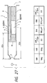
- Fig. 27 illustrates the area, disposition and so forth of discharge heaters of an ink-jet recording head according to a fifth embodiment of the present invention.
- Fig. 28 is a graph showing the relationship between discharge quantity ratio and area ratio for each heater in an instance where a plurality of heaters are provided in one ink flow path.
- Figs. 29A and 29B illustrate the structure of a discharge heater.
- Fig. 30 illustrates an effective bubbling region and a non-bubbling region on the discharge heater.
- Figs. 31A, 31B, 31C and 31D illustrate how the ink-jet recording head according to the fifth embodiment is driven.
- Fig. 32 is a partially broken perspective view of the ink-jet recording head having an ink flow path structure according to the fifth embodiment shown in Fig. 27.
- Fig. 33 is a perspective view showing another structural example of an ink-jet recording head to which the present invention is applied.
- Fig. 34 illustrates the area, disposition and so forth of discharge heaters of an ink-jet recording head according to a first modification in the fifth embodiment of the present invention.
- Fig. 35 illustrates the area, disposition and so forth of discharge heaters of an ink-jet recording head according to a second modification in the fifth embodiment of the present invention.
- Fig. 36 illustrates the area, disposition and so forth of discharge heaters of an ink-jet recording head according to a third modification in the fifth embodiment of the present invention.
- Fig. 37 illustrates a third embodiment of the present invention.
- Figs. 1A and 1B are diagrammatic plan views showing the construction of an ink-jet recording head according to an embodiment of the present invention and that of a conventional product as a comparative example, respectively, at their nozzle portions.
- Fig. 1A shows the construction of an edge-shoot type head that discharges liquid in the direction substantially vertical to the surface on which a heating element is formed.
- Nozzles (101) are arranged in a density of 360 dpi.
- two heaters 102 having the same size and the same length are provided side by side in such a manner that the distance from a discharge opening 104 to each heater is different.
- nozzles (105) are arranged in the same density as in the embodiment shown in Fig. 1A, but, in each nozzle 105, only one heater 106 is provided.
- the distance from the discharge opening 107 to the heater 106 is represented by OH
- the distance from the discharge opening 107 to the center of gravity of the heater 106 OC.
- the two heaters are so set up that they can be driven independently from each other, where the discharge quantity of small ink drops for each heater is set to about 20 pl.
- the discharge quantity of small ink drops for each heater is set to about 20 pl.
- large ink drops with a discharge quantity of about 40 pl are discharged which are about twice the discharge quantity in the discharge from either head.
- Figs. 2A to 2C are graphs showing discharge quantity Vd, discharge velocity v and refill frequency fr, respectively, of ink droplets in the case when the distance OH from the discharge opening to the heater end is assumed as a variable.
- the discharge quantity Vd of ink droplets stands maximum at a value assigned by a certain distance OH indicated in Fig. 2A by a one-dotted chain line, and decreases as the distance comes apart from the certain distance OH.
- the discharge velocity v increases with a decrease in the distance OH as shown in Fig. 2A.
- the refill frequency fr contrary to the discharge velocity v, decreases with a decrease in the distance OH as shown in Fig. 2C.
- Fig. 3 is a graph showing the relationship between the discharge quantity Vd and discharge velocity v of ink droplets, the product of discharge opening area SO and distance OH from the discharge opening to the heater end (SO ⁇ OH), and the distance OH.
- Fig. 4 is a graph showing the relationship between the results given by dividing discharge velocity v by discharge quantity Vd (v/Vd) and the distance OH.
- singular points a and b are defined from a viewpoint different from the certain distance OH as described above, and the distance OH is classified into three regions, i.e., region A not longer than a, region B not shorter than b, and region C extending between a and b.
- the discharge velocity v and the discharge quantity Vd have a relation substantially proportional to an increase in the distance OH and hence the value of v/Vd is substantially constant.
- the discharge quantity Vd is substantially proportional to the product of discharge area SO and distance OH, and, in the region C, the discharge quantity Vd is substantially constant.
- the discharge velocity v and discharge quantity Vd of ink droplets greatly depend on the (inertial) resistance of a nozzle at its part on the discharge opening side of the heater and the (inertial) resistance at the rear of the heater, and also are determined from the relation that the discharge quantity Vd does not greatly exceed the product of discharge opening area SO and distance OH from the discharge opening to the heater end.
- the region A (second region) in Fig. 3 stands in the relation of SO' ⁇ OH ⁇ Vd (SO' is a proportionality factor). That is, it is a region where the discharge velocity v and the discharge quantity Vd are determined in accordance with, e.g., the balance of (inertial) resistance between the rear (liquid chamber side) and the front (discharge opening side).
- F and R the inertial resistance at the front of the heater and the inertial resistance at the rear thereof
- the discharge velocity v and discharge quantity Vd are substantially proportional to R/(F+R) .
- the inertial resistance at the front of the heater increases with an increase in the distance OH.
- the inertial resistance at the rear of the heater decreases with it, and hence the force toward the discharge opening side becomes weak, resulting in a decrease in velocity and quantity of the ink moving toward the discharge opening side. This matter will be more detailed below.
- Fig. 5 cross-sectionally illustrates an ink flow path of an ink-jet recording head commonly available.
- a top plate 413 in which an ink-flow path groove has been formed and a heater board 403 are joined to make up an ink flow path 401.
- the ink flow path 401 communicates with a common liquid chamber 407 and is filled with an ink 406.
- a heater 404 that generates heat energy for discharging the ink is formed, by means of which the ink 406 in the ink flow path 401 is heated to produce bubbles by vaporization.
- the ink 406 forms a meniscus at a given position in the vicinity of an orifice 405 because of the balancing of the negative pressure in an ink tank (not shown) and the capillary force (flow path resistance) in the ink flow path 401.
- the bubbles undergo volumetric changes to produce a pressure, so that the ink 406 present in the ink flow path 401 at its part frontward from the heater 404 are discharged in the form of droplets. Thereafter, the ink 406 remaining in the ink flow path 401 at its part frontward from the heater 404 acts to return to the heater side, thus the meniscus recedes.
- Vb [R/(F+R)] ⁇ Vb wherein Vb is proportional to SH (heater size).
- the region B (first region) is a region where Vd ⁇ SO' ⁇ OH .
- the inertial resistance at the part frontward from the heater becomes smaller, and hence the velocity v increases.
- the bubble produced and present on the heater is an obstacle to the flow of ink in the nozzle toward the discharge opening side to intercept the flow, and consequently the discharge quantity Vd decreases without being proportional to the discharge velocity v.
- a state of no ink feeding takes place even though it is expected for the supplied power to provide a much larger discharge quantity Vd.
- a limited discharge quantity Vdlim is given which is formed by the discharge opening area SO and the distance OH extending from the discharge opening to the heater end. This relation is expressed by the following expression (2).
- Vdlim SO ⁇ OH
- Fig. 8 shows a general relationship between the discharge quantity Vd and the distance OH, and is a graph showing how the curves a and b change with a change in the heater area SH. As is seen from Fig. 8, the curves a and b shift in accordance with the dimensions of the heater area SH.
- the course of action of the refill i.e., bubbling ⁇ debubbling ⁇ meniscus formation will be described below with reference to Figs. 9A to 9D.
- the bubble 408 is produced at a time t1 by heating by means of the heater 404 (Fig. 9A), whereupon at a time t2 it comes to stand as shown in Fig. 9B.
- the bubble 408 disappears (debubbling) at a time t3.
- the amount of meniscus regression is small and the refill frequency fr is high.
- the amount of meniscus regression is large and the refill frequency fr is low.
- the ink flow path is classified into the region A and the region B on the basis of the distance OH at which the discharge quantity Vd reaches a maximum value in the case when the distance OH is assumed as a variable.
- the discharge quantity Vd is in a very gentle curve which is substantially constant with respect to the distance OH.
- the frontward heater does not intercept the whole flow path of the nozzle and does not perfectly intercept the flow of ink, thus the ink can be fed from the side (lateral position) of the frontward heater.
- the inertial resistance at the part on the front side of the heater decreases when the ink partly projects from the end of the nozzle (the discharge opening) at the initial stage of discharge, so that the viscosity resistance becomes predominant to make slow the flow of ink in the nozzle, and the discharge quantity Vd gradually decreases especially when the distance OH is made shorter where such effect is not expected.
- the distance OH is relatively long, relatively good values are obtained also on the refill frequency fr.
- the proportionality factor SO' shows a smaller value than the discharge opening area SO.
- this proportionality factor SO' as an effective discharge opening area, it can be considered that the effective discharge opening area becomes smaller as the heater width becomes narrower.
- the SO' on the abscissa in Fig. 10 as the effective discharge opening area, the value of discharge opening diameter 2(SO'/ ⁇ ) 1/2 in such an instance is made to correspond.
- one heater i.e., the frontward heater, calling the discharge opening side as "frontward” has a heater width so set that the effective discharge opening area is smaller (about half) than SO and also its heater position is so set that the distance OH corresponds to the region B (or the region C, the second region), and the other heater (the rearward heater) has substantially the same size as the frontward heater and its heater position is so set that the distance OH corresponds to the region A (or the region C), and the other heater (the rearward heater) has substantially the same size as the frontward heater and its heater position.
- the heaters are so set that they have substantially the same discharge quantity when they are independently driven (small ink drops) by the respective heaters, and that they have a doubled discharge quantity when the both are simultaneously driven (large ink drops).
- the discharge quantity ratio of large and small ink drops is set to be 2:1
- the distance OH of each heater may be set so as to be symmetrical to the distance coming to be a flex point. This makes it easy to drive the heaters, and it is preferable to provide them in this manner.
- the frontward heater may be driven to discharge small ink drops and the frontward and rearward heaters may be simultaneously driven to discharge large ink drops so that small ink drops can be discharged at a higher velocity and also the large and small ink drops can be discharged in a smaller difference (or ratio) in discharge velocity.
- the distance OH of the frontward heater if it is too short, the discharge velocity v increases but the refill frequency fr decreases, and also the bubbles of the frontward heater may communicate with the atmosphere (what is called the bubble-through). In such a state, the desired condition of discharge can not be obtained when the frontward heater and rearward heater are simultaneously driven. Accordingly, the distance OH of the frontward heater may be set in such a range that the bubbles do not communicate with the atmosphere and the drive frequency can be satisfied. Stated specifically, the distance OH may preferably be at least 30 ⁇ m.
- the large ink drops are discharged when the frontward and rearward two heaters are simultaneously driven.
- the discharge characteristics such as discharge quantity Vd, discharge velocity v and refill frequency fr are as shown in Figs. 11A to 11C, respectively.
- the distance OH1 of the frontward heater is set stationary, and the distance OP obtained by changing the distance OH2 of the rearward heater is set as a variable.
- the discharge quantity Vd in the above instance is known to be approximately equal to the sum of discharge quantities obtained when the frontward heater and the rearward heater are each driven alone, and the discharge quantity Vd reaches a maximum when the distance OP is a certain distance.
- the distance OP is set at a larger value than this certain distance.
- the discharge quantity Vd, discharge velocity v and refill frequency fr of ink droplets can be made approximately equal by making the OP approximately equal to the OC of a former-type product. If the distance OH1 of the frontward heater is made too small in order to improve the discharge velocity v, it becomes necessary to make the distance OH2 of the rearward heater longer. If, however, the distance OH2 is made excessively longer in order to ensure OC ⁇ OP, there is a possibility that the bubbles produced go through the rear at which a feed system for feeding ink to the nozzle is provided. Hence, to prevent this, the OP may preferably be made smaller than OC (OP ⁇ OC).
- the ink may be discharged in a poor stability if the distance OH is in the region B.
- the distance OC may preferably be so set that the distance OH is in the region A.
- Fig. 12 illustrates the shapes of a nozzle and heaters used to make the measurement.
- a nozzle 104 communicate with a liquid chamber 51.
- a meniscus 52 is formed in the vicinity of an orifice by a capillary force.
- At least two heaters are provided in the nozzle.
- the nozzle has a whole length L of 400 ⁇ m.
- the heaters A and B are respectively connected with electrodes, and a common electrode is connected to the opposite side terminals. To the top of the respective electrodes, switching means are connected so that the heaters A and B can be selectively driven to discharge the ink held in the nozzle.
- Small ink drops are discharged by driving the heater A only to produce bubbles and large ink drops are discharged by driving the heaters A and B simultaneously to produce bubbles, thus evaluation is made.
- Ink used is an ink having a surface tension of about 40.5 to 46.5 dyne/cm and a viscosity of 1.5 to 2.1 cP.
- the discharge opening has an opening area SO of 680 ⁇ m 2 .
- Table 1 which shows the results of first measurement, is a table showing the relationship between heater construction, discharge quantity and discharge velocity, and occurrence of ink mist when discharged at 6.5 kHz.
- the discharge velocity and discharge quantity Vd for small ink drops and large ink drops are sufficient for performing high-quality printing and, since the ink mist very little occurs.
- the discharge velocity of small ink drops gradually becomes slow when the distance OH of the heater A exceeds 120 ⁇ m, and no high-grade printing can be expected. Also, the ink mist greatly occurs when it is 70 ⁇ m or lower. This is presumably because the refill frequency fr becomes poor and the discharge becomes unstable.
- Table 3(b) shows the discharge velocity of large ink drops with respect to the distance OH of heater B, setting the distance OH of heater A to 100 ⁇ m. At distance OH of 110 ⁇ m or smaller, ink mist occurs when large ink drops are discharged, and the direction of discharge curves to cause a lowering of ink droplets shot precision. At distance OH of 200 ⁇ m or larger, the ink is not discharged occasionally.
- the distance OH of the heater for discharging small ink drops may be set at 80 to 130 ⁇ m and the difference in distance OH between the two heaters may be set at 10 to 80 ⁇ m.
- the difference in distance OH between them may be set at 20 to 60 ⁇ m.
- discharge characteristics were measured when the distance OH of the rearward heater was set stationary at 170 ⁇ m and the position of the frontward heater was changed. Measurement was made on samples having different discharge opening areas SO and frontward heater and rearward heater areas SH.
- Figs. 13A to 13D and Figs. 14A to 14D Results obtained are shown in Tables 4 and 5, and their graphic representations are shown in Figs. 13A to 13D and Figs. 14A to 14D, respectively.
- Figs. 13A and 14A concern the discharge velocity v
- Figs. 13B and 14B the discharge quantity Vd
- Figs. 13C and 14C the value given by dividing discharge velocity v by discharge quantity Vd.
- samples used have discharge opening area SO of 380 ⁇ m 2
- the frontward heater and rearward heater used both have area SH of 17 ⁇ m ⁇ 135 ⁇ m.
- samples used have discharge opening area SO of 400 ⁇ m 2
- ink used has a surface tension of about 26.0 to 37.0 dyne/cm and a viscosity of 1.85 to 2.60 cP to make measurement on discharge velocities vF and vF+B and discharge quantities VdF and VdF+B when small ink drops and large ink drops are discharged.
- the ink-jet recording head constructed as described above is mounted on a cartridge having a scanning speed of 0.7 m/s, and then mounted on a recording apparatus having a distance to recording medium, of 1 mm, where flying time and ink shot positional deviation are examined.
- a first value given by dividing discharge velocity by discharge quantity in the discharge of small ink drops and a second value given by dividing discharge velocity by discharge quantity in the discharge of large ink drops are found, and still also a value given by dividing the first value by the second value is found.
- preferable discharge velocity, discharge quantity ratio, ink shot positional deviation and refill frequency can be attained when the first value is greater than the value given by multiplying the second value by a proportionality factor 1.15, i.e., when discharge velocity vF and vF+B and discharge quantity VdF and VdF+B satisfy the relation of: (vF/VdF) ⁇ (vF+B/VdF+B) ⁇ C wherein C is a constant.
- C varies depending on physical properties of ink, and experiments made by the present inventors have revealed that C is 1.15 when an ink having a surface tension of about 26.0 to 37.0 dyne/cm and a viscosity of 1.85 to 2.60 cP is used and C is 1.0 when an ink having a surface tension of about 40.5 to 46.5 dyne/cm and a viscosity of 1.5 to 2.1 cP is used. This is presumably because the ink having a greater surface tension is brought back at a greater force when ink droplets are separated and hence more greatly affects the discharge velocity with respect to small ink drops to make the value C smaller.
- a second embodiment of the present invention will be described below. This embodiment is concerned with the shape and center of gravity of heaters.
- Heaters each having a stated area are necessary for obtaining a stated ink droplet volume in ink-jet recording apparatus in which heaters are driven to cause the ink present thereon to bubble to discharge ink droplets.
- the heater width In order to provide nozzles in a higher density, the heater width must be made smaller. In such an instance, the heater area must be made equal in order to attain the same ink droplet volume as a heater with a large width, so that the heater length is necessarily made larger. The width must be made much smaller when a plurality of heaters are arranged in one nozzle in parallel to the direction of the line of nozzles, so that the heater length is made much larger.
- Figs. 15A and 15B each illustrate the second embodiment of the present invention which takes account of the above characteristics, and are plan views for showing the construction of nozzles 1001 and 1005 that discharge substantially the same ink droplets. These are views used to explain that characteristics differ depending on heater shapes.
- a frontward heater 1002 and a rearward heater 1003 are provided in a nozzle 1001 in a nozzle 1001.
- a frontward heater 1006 and a rearward heater 1008 are provided in a nozzle 1005 having the same shape as the nozzle 1001.
- the heater 1002 (or 1003) has a smaller width and a larger length than the heater 1006 (or 1008), but is made to have substantially an equal area, and the respective heaters are so provided that their positions of center of gravity with respect to the nozzles 1001 and 1005 are equal. Since the heaters are provided under such conditions, the distance OH1 from a discharge opening 1004 to the frontward heater 1002 in the nozzle 1001 shown in Fig.
- thermoelectric transducers in each ink flow path are provided in the direction parallel to the ink flow path.
- present embodiment show an example in which a plurality of thermoelectric transducers are provided in the direction of ink flow in the ink flow path.
- the rearward heater has a width sufficiently larger than the frontward heater. More specifically, when constructed in this way, the frontward heater does not intercept the whole flow path of the nozzle, and the ink can be fed from the both sides (lateral positions).
- Fig. 37 illustrates the present embodiment, and shows the shape and disposition of heaters.
- frontward heaters 102 and rearward heaters 103 each have the following shape and disposition.
- the present embodiment also satisfy v/Vd (0.571) > v'/Vd' (0.543).
- the discharge opening area SO is 310 ⁇ m 2 .
- the present embodiment shows an example in which a protective layer is provided to protect the thermoelectric transducer, which is preferable when a plurality of thermoelectric transducers are provided in the direction of ink flow in the ink flow path as in the case of the third embodiment.
- the frontward heater and the rearward heater are constructed to have substantially equal lengths.
- some flow path construction may make it impossible for both the heaters to have equal lengths. In such a case, the bubbling voltage of each heater may deviate.
- the layer thickness of a protective layer of the rearward heater with a larger size is made smaller than the layer thickness of a protective layer of the frontward heater with a smaller size or the layer thickness of a heat accumulation layer of the rearward heater with a larger size is made smaller than the layer thickness of a heat accumulation layer of the frontward heater with a smaller size so that any deviation of bubbling voltage can be corrected.
- Figs. 23 and 24 are cross-sectional views of ink-jet recording heads according to the present embodiment, at their substrate portions of heaters for bubbling ink.
- Fig. 23 is a partial cross-sectional view of a frontward heater portion cut in the direction vertical to the substrate surface.
- Fig. 24 is a partial cross-sectional view of a rearward heater portion cut in the direction vertical to the substrate surface.
- an Si substrate 2120 is used.
- a driving IC may have been already built in.
- an SiO 2 heat accumulation layer is previously formed beneath a resistance heater element by thermal oxidation, sputtering, CVD or the like.
- the SiO 2 heat accumulation layer is formed during the process of its production.
- reference numeral 2106 denotes that portion.
- a TaN layer 2107 is formed as the resistance heater element by reactive sputtering in a thickness of of about 1,000 ⁇ , and Al layers 2103 and 2104 as electrode wiring are formed by sputtering in a thickness of 6,000 ⁇ .
- a wiring pattern is formed by photolithography, and Al is removed by wet etching. Thereafter, a pattern is again formed and TaN is removed by reactive ion etching to form Al electrodes and a resistance heater element portion 2102.
- the terminal of Al wiring extending from the Al electrode serves as a pad for wire bonding in the case of the Si substrate, and, in the case of the IC built-in substrate, it is connected to the underlying electrode via a through-hole.
- a PSG layer (a phosphorus glass layer, hereinafter "PSG layer") as a film that covers the Al electrode is formed by CVD in a thickness of about 7,000 ⁇ , and photolithography is carried out to remove only the PSG layer of the resistance heater element portion with a smaller size by wet etching.
- an SiN layer 2108 is formed by CVD in a thickness of about 3,000 ⁇ .
- a protective film formed of 7,000 ⁇ PSG and 3,000 ⁇ SiN is formed on the Al wiring, and a protective film formed of 3,000 ⁇ SiN is formed on the resistance heater element portion.
- a protective film of 10,000 ⁇ thick in total is formed on the large-size resistance heater element portion shown in Fig. 24, and a protective film of 3,000 ⁇ thick is formed on the small-size resistance heater element portion shown in Fig. 23.
- a Ta layer as a cavitation-resistant and ink-resistant film is formed by sputtering in a thickness of about 2,500 ⁇ as denoted by reference numeral 2110 in Figs. 23 and 24.
- the Ta layer is patterned by photolithography to finally make pad windows for wire bonding where the PSG and SiN layers are superposed, thus the substrate for the heater of the ink-jet recording head, where the ink is bubbled, is produced.
- the protective film at the upper part of the large resistance heater element of the large and small two resistance heater elements is thinner than the protective film at the upper part of the small resistance heater element, thus values of bubbling voltage Vth for bubbling ink at the two resistance heater elements can be put in order.
- Figs. 25 and 26 are cross-sectional views of ink-jet recording heads according to a modification of the present embodiment, at their substrate portions of heaters for bubbling ink.
- Fig. 25 is a partial cross-sectional view of a frontward heater portion cut in the direction vertical to the substrate surface.
- Fig. 26 is a partial cross-sectional view of a rearward heater portion cut in the direction vertical to the substrate surface.
- an Si substrate 2120 is used.
- a driving IC may have been already built in.
- an SiO 2 heat accumulation layer is previously formed beneath a resistance heater element by thermal oxidation, sputtering, CVD or the like.
- reference numeral 2106 denotes that portion.
- thermolithography is used to locally bore the heat accumulation layer at the part of the large-side resistance heater element by wet etching.
- the heat accumulation layer having been bored has, as shown in Fig. 25, a smaller thickness at the lower part of the resistance heater element portion.
- a TaN layer 2107 is formed as the resistance heater element by reactive sputtering in a thickness of of about 1,000 ⁇ , and Al layers 2103 and 2104 as electrode wiring are formed by sputtering in a thickness of 6,000 ⁇ .
- a wiring pattern is formed by photolithography, and Al is removed by wet etching. Thereafter, a pattern is again formed and TaN is removed by reactive ion etching to form Al electrodes and a resistance heater element portion 2102.
- the terminal of Al wiring extending from the Al electrode serves as a pad for wire bonding in the case of the Si substrate, and, in the case of the IC built-in substrate, it is connected to the underlying electrode via a through-hole.
- an SiN layer 2108 as a protective film is formed by CVD in a thickness of about 10,000 ⁇ .
- a Ta layer 2110 as a cavitation-resistant film is formed by sputtering in a thickness of about 2,500 ⁇ .
- the heat accumulation layer at the lower part of the small resistance heater element of the large and small two resistance heater elements is locally thinner than the heat accumulation layer at the lower part of the large resistance heater element, thus values of bubbling voltage Vth for bubbling ink at the two resistance heater elements can be put in order.
- the present embodiment is concerned with an ink-jet recording head in which not only the frontward heater but also the rearward heater are driven alone so that it can take small and medium two values, or three values with a large value added thereto, especially taking note of the sizes and shapes of frontward and rearward heaters.
- thermoelectric transducers in the construction having two or more thermoelectric transducers, a specific manner for modulating discharge quantity is commonly a method in which, in the instance where two thermoelectric transducers (hereinafter also “discharge heaters") are provided in one ink flow path and it is intended to discharge ink in respectively different quantities, the head is so designed that the ratio of sizes of the respective discharge heaters is identical to the ratio of the respective discharge quantities.
- discharge heaters two thermoelectric transducers
- the designing of the ink flow path in order to attain the desired discharge quantity in a high precision for each discharge heater or in order to maintain the discharge stability of each head at a high level has failed even to satisfy practical levels, because of the presence of two discharge heaters that has entangled complex factors.
- the size of each discharge heater is fixed at the time when photomasks for patterning substrates are designed in the semiconductor fabrication process, and hence, to change the size for attaining the desired discharge quantity, the head must be remade from the beginning. Accordingly, the post changing of the balance of discharge quantities assigned to the respective discharge heaters results in a reasonable loss not only from the viewpoint of time but also from the viewpoint of work load. On the other hand, if only the balance of discharge quantities, i.e., the ratio of discharge quantities can be fixed, other discharge characteristics could be controlled relatively with ease.
- the position of discharge heaters with respect to an ink flow path can be set when the substrate is cut out of a wafer, and the orifice area can be changed by controlling the energy of lasers for making orifice openings. These also make it free to change their values minutely, and can be handled in relatively later steps to less cause the loss of time and work.
- the present inventors examined discharge stabilizing conditions required for a plurality of discharge heaters when specific discharge quantities are made different. As a result, with regard to the ratio of discharge quantities that is very important for designing heads, they have taken note of how the area ratio of discharge heaters (preferably the size and shape of each individual discharge heater) affects ink discharge, and have confirmed that the stated discharge quantities assigned to the respective discharge heaters can be attained in a high precision and a stable state by appropriately controlling this area ratio.
- each discharge heater there are a heat release region utilized for actual discharge energy and a heat release region not utilized for discharge energy. This is due to temperature distribution at the time the discharge heater is driven and heat is released. More specifically, the discharge heater has a lower heat release temperature at its periphery than at its center, and hence this peripheral region stands as a non-bubbling region that does not reach the temperature high enough to heat and bubble the ink, thus the heat at that region is not utilized as discharge energy. In contrast, in the discharge heater, a bubbling region that reaches the temperature at which the ink is bubbled is herein called an effective bubbling region. Accordingly, based upon this standpoint, the desired discharge quantity can be stably attained by designing a plurality of discharge heaters according to the following methods.
- the area of each discharge heater be designed at a ratio smaller than that ratio.
- the ratio of width of the respective discharge heaters be designed so as to be equal to the ratio of widths given by respectively subtracting a length of 1 ⁇ m to 10 ⁇ m.
- the ratio of discharge quantities assigned to the respective discharge heaters be substantially in agreement with the ratio of effective bubbling region areas of the respective discharge heaters.
- the effective bubbling region areas stated in the third be in a ratio given by subtracting an area of 1 ⁇ m to 10 ⁇ m from the periphery of the area of each discharge heater.
- the present embodiment aims at providing an ink-jet recording head that can stably attain the desired discharge quantity for each discharge heater as stated above and also has solved the basic problem involved in the heads having a plurality of discharge heaters in one ink flow path, and an ink-jet recording apparatus employing such an ink-jet recording head.
- the ink-jet recording head comprises an ink flow path having a discharge opening for discharging an ink and a plurality of thermoelectric transducers provided for one ink flow path, which satisfies the relation of Vd1/Vd2 ⁇ Sh1/Sh2 when the areas of two thermoelectric transducers among the plurality of thermoelectric transducers are represented by Sh1 and Sh2 (Sh1 > Sh2) and the ink discharge quantities assigned to the respective two thermoelectric transducers are represented by Vd1 and Vd2, respectively; and satisfies the relation of OC1 > OC2 when the distances between the respective area centers and discharge openings of the two thermoelectric transducers are represented by OC1 and OC2.
- the ink-jet recording apparatus comprises an ink-jet recording head comprising an ink flow path having a discharge opening for discharging an ink and a plurality of thermoelectric transducers provided for one ink flow path; the ink being discharged onto a recording medium to make a record, wherein;
- thermoelectric transducer when the ratios of discharge quantities and area ratios concerning the two thermoelectric transducers satisfy the relation of Vd1/Vd2 ⁇ Sh1/Sh2, the discharge quantity assigned to each thermoelectric transducer can be attained in a good efficiency in the stated ratio. Also, the distance between a thermoelectric transducer having a smaller area and the discharge opening is made relatively short, and hence the discharge power relative to ink thickening or the like can be prevented from lowering.
- Fig. 27 is a diagrammatic cross-sectional view for chiefly showing an ink flow path and thermoelectric transducers (herein also “discharge heaters”) provided in the ink flow path, according to the present embodiment.
- thermoelectric transducers herein also “discharge heaters”
- the ink-jet recording head is provided with a plurality of orifices 1A and a plurality of ink flow paths 1 (in the drawing, one orifice and one flow path of these are illustrated).
- Ink flow path 1 communicates with a liquid chamber 2, and ink fed from this liquid chamber 2 forms a meniscus in the vicinity of each orifice 1A by the action of capillary force.
- the present invention is applied to the construction having two or more discharge heaters provided in one ink flow path.
- an ink flow path construction provided with two discharge heaters will be described. More specifically, two discharge heaters A4 and B6 are provided in each ink flow path 1, and their area and disposition are made different from each other.
- the area of the discharge heater A4 having a smaller area is represented by ShA
- the area of the discharge heater B6 having a larger area is represented by ShB.
- selective electrodes 8 and 9 are respectively connected, and to the other ends thereof a common electrode 10 is connected in common.
- switching devices such as transistors (not shown) are respectively connected, whereby the discharge heaters A and B can be selectively driven.
- the discharge quantities given by individually driving the discharge heaters A and B are represented by VdA and VdB, respectively, the VdA is 15 ng and the VdB is 30 ng.
- the areas ShA and ShB of the discharge heaters A and B are 950 ⁇ m 2 and 2,210 ⁇ m 2 , respectively.
- This relation is set up by making the small-area discharge heater A4 close to the orifice 1A side, when the areas of the discharge heaters A and B are assumed as being stationary. More specifically, since the discharge heater A4 may have a relatively small discharge power against the ink having thickened, faulty discharge may occur. In order to prevent this, the distance OCA from the area center of the discharge heater A to the orifice 1A is made smaller.
- a solid line shown in Fig. 28 indicates a discharge quantity ratio given when the ratio of ShB to ShA relative to certain OCA and OCB is changed. In the case of such an ink flow path, it is within the range that fulfills the conditions of the present invention, and hence the effect of the present invention can be attained.
- the surfaces of the respective discharge heaters are, as previously described, classified into effective bubbling regions (5 and 7 in Fig. 27) that can bubble the ink and non-bubbling regions (4 and 6 in Fig. 27) that do not reach the temperature high enough to bubble the ink in heat gradient.
- the head having the structure as shown in Fig.
- the discharge quantity may inversely decrease.
- the distance OCA is outside such a region, i.e., larger than the above certain value.
- OCB > OCA can be set up even under the conditions of VdB/VdA > ShB/ShA (provided that VdB > VdA) if the ratio of OCB to OCA is small.
- the discharge heater used in the present embodiment is constructed as described below.
- a heat accumulation layer 105 comprised of an insulating material such as SiO 2 is formed, and a resistance layer 101 is formed thereon followed by patterning.
- a protective layer 103 making use of an insulating material such as SiO 2 or SiN and a cavitation-resistant layer 104 for absorbing shock waves due to bubbling-debubbling are formed.
- a voltage is applied through electrodes 9 and 10 to produce electric currents, so that the resistance layer 101 generate heat.
- the thermoelectric transducer discharge heater
- the discharge heater area referred to in the above is the area of the resistance layer 101 at its part not covered with the electrodes 9 and 10.
- the heat generated in the resistance layer escapes in the direction of film overlap at the middle portion of the discharge heater 1, and also escape in the direction of film spread at the edge portion Hence, at the surface of the discharge heater on its side coming in contact with ink, its temperature is lower at the edge portion of the discharge heater than at the middle portion thereof.
- the surface temperature distribution of the discharge heater in this state can be viewed on the line 29B-29B in Fig. 29A, where it stands as shown by temperature distribution in Fig. 30.
- ⁇ T1 is a minimum temperature at which the ink on the discharge heater bubbles
- ⁇ T2 is a temperature at which the discharge heater comes to have a too high temperature and may undergo damage such as heat stress to have an extremely short lifetime. Accordingly, when it is intended to stably control the temperature of the discharge heater to ink bubbling temperature without damaging its lifetime, it necessarily follows that the non-bubbling region that does not reach the bubbling temperature is present at the edge portion of the discharge heater as shown in Fig. 30.
- the non-bubbling region has a width of about 3 ⁇ m to about 5 ⁇ m, which may differ depending on the constitution and material of the film and driving conditions and must take account of a range of from about 1 ⁇ m to about 10 ⁇ m according to conditions.
- the two discharge heaters partly have portions that are side by side adjacent to each other in the direction falling at right angles with the longitudinal direction of the ink flow path, i.e., the direction of ink flow.
- the escape of heat in the direction of film overlap at the portions adjacent to each other acts on the adjacent discharge heater and is utilized as the heat of that discharge heater, so that the temperature distribution at the edge portion of the discharge heater can be prevented from lowering and consequently the effective bubbling region at that portion expands to bring about an advantage of the improvement in discharge efficiency.
- FIG. 31A an ink flow path 1 held between ink flow path walls 109 is filled with ink.
- the ink Upon driving discharge heaters A4 and B6 to heat and bubble the ink, the ink is discharged from an orifice 3 by the action of bubbling pressure.
- Fig. 31B shows a state in which the small-size discharge heater A4 generates heat and a small drop 11 is discharged by small bubbling 113. The discharge quantity in this case is assumed to be about 30 ng.
- Fig. 31C shows a state in which the large-size discharge heater B6 generates heat and a large drop 11 is discharged by large bubbling 112.
- the large-size discharge heater B6 When the large-size discharge heater B6 is designed to have an effective bubbling area twice as large as the small-size discharge heater A4 as previously stated, it gives a discharge quantity of about 60 ng since the discharge quantity is proportional to the effective bubbling area.
- Fig. 31D shows a state in which both the discharge heaters are driven to heat and bubble the ink. In this case, the discharge quantity is 90 ng, which is the total of discharge quantities assigned to the respective discharge heaters.
- FIGs. 32 and 33 The both are constitutions called an edge shooter type and a side shooter type, respectively, where the ink in each ink flow path 1 is heated and bubbled by the discharge heaters A4 and B6 and the ink is discharged from orifices 3 made open sideward or upward.
- a substrate 23 is bonded to a base plate 41, and ink walls 109 are formed integrally with a top plate 101.
- the edge shooter type head as shown in Fig. 32 is a head employing, as it is, the head having the ink flow path structure shown in Fig. 27.
- the positional relation of discharge heaters may affect the distance from the discharge heaters to the discharge opening in a smaller proportion from a structural point of view, but the relation of the present invention as previously described can be set up when the distance from discharge opening center to heater center is represented by the OCA or OCB (similar to Fig. 27).
- Fig. 34 is a diagrammatic cross-sectional view showing the construction inside an ink flow path according to a first modification of the present embodiment.
- VdA is 15 ng and VdB is 30 ng, where the areas ShA and ShB of thermoelectric transducers are 950 ⁇ m 2 and 2,210 ⁇ m 2 , respectively.
- the present modified embodiment also satisfies the relation of VdB/VdA ⁇ ShB/ShA. More specifically, since the small-size discharge heater A4 may have a relatively small discharge power as previously stated, the lengths LA and LB of discharge heaters are made to satisfy the relation of LA ⁇ LB in order to prevent faulty discharge due to ink thickening.
- the distances from orifice-side ends of both the discharge heaters to the orifice are made equal, the distance OCA from the area center of the small-size discharge heater A4 to the orifice is made shorter than the corresponding distance OCB of the large-size discharge heater B6, i.e., OCA ⁇ OCB (similar to Fig. 27).
- Fig. 35 illustrates a second modification of the present embodiment.
- this modified embodiment an example is shown in which the area and disposition of the respective discharge heaters are fixed on the basis of the ratio of discharge quantity VdAB given when both the discharge heaters are driven, to discharge quantity VdA assigned to the small-size discharge heater A4.
- the relative disposition itself of the large and small two discharge heaters in the present modified embodiment is the same as that shown in Fig. 27.
- the discharge quantity VdA of the small-size discharge heater A4 is 15 ng
- the discharge quantity VdA+B given when the large and small both discharge heaters B6 and A4 are driven is 45 ng
- the total area ShA+B of the large and small heaters is 3,150 ⁇ m 2 .
- area ratio ShA+B/ShA gives 3.3.
- the respective discharge quantities can be attained in a good precision and a linear gradation can be maintained, in both the cases when the large and small heaters are individually driven and when both the heaters are simultaneously driven. Also, high-density recording can be well performed especially in a large discharge quantity mode in the driving of the both heaters.
- Fig. 36 illustrates an ink flow path structure according to a third modification of the present embodiment, and shows an example in which like the second modified embodiment the area and so forth of the respective discharge heaters are fixed on the basis of discharge quantities at the time the both discharge heaters are driven.
- the ink flow path shown in Fig. 36 has the same structure as that according to the third modified embodiment shown in Fig. 34.
- the discharge quantity VdA of the small-size discharge heater A4 is 15 ng
- the discharge quantity VdA+B given when the large and small both discharge heaters B6 and A4 are driven is 48 ng
- the total area ShA+B of the large and small heaters is 3,250 ⁇ m 2 .
- area ratio ShA+B/ShA gives 3.4.
- the discharge quantity ratio and area ratio concerning the two thermoelectric transducers satisfy the relation of Vd1/Vd2 ⁇ Sh1/Sh2, and hence the discharge quantities assigned to the respective thermoelectric transducers can be attained at the stated ratio and in a good precision. Also, the distance between the thermoelectric transducer having a smaller area and the discharge opening is made relatively short, and hence the relative discharge power can be prevented from lowering against ink thickening or the like.
- the desired discharge quantity can be obtained in each discharge quantity mode and, images with gradation having a good linearity can be obtained.
- a turning point between the region A and the regions B and C, the regions other than the region A is specified to be 130 ⁇ m according to what is shown in Fig. 4, and also, from the measurement results, the discharge velocities vF and vF+B and discharge quantities VdF and VdF+B are specified in accordance with the type of ink.
- the large ink drops and small ink drops can be well discharged.
- Fig. 16 illustrates a combination of ink-jet recording head cartridges A to D making use of ink-jet recording heads having the characteristics as described above.
- Y yellow
- M magenta
- C cyan
- Bk black
- the ink-jet recording heads constituting the ink-jet recording head cartridges A to C those in which the constant C in the relation of (vF/VdF) ⁇ (vF+B/VdF+B) ⁇ C is 1.15 are used.
- the constant C is 1.00 is used.
- the working mode of the embodiments described above embraces all embodiments in which both heaters having the same shape are so provided that they are partly adjacent side by side as shown in Fig. 17A, heaters having the same shape are so provided that they are not adjacent side by side as shown in Fig. 17B, heaters having different shapes are so provided that they are not adjacent side by side as shown in Fig. 17C, and heaters having different shapes are so provided that they are adjacent side by side as shown in Fig. 17D.
- the ink-jet recording heads are described taking examples of those provided with two heaters in one ink flow path.
- the concept of the present invention can also be applied to instances where still more heaters are provided in one ink flow path.
- these may be regarded as one heater and the present invention may be applied to its center of gravity.
- heaters having a front and rear relation may be regarded as one heater and the present invention may be applied to its center of gravity.
- the embodiments described above may be combined so that the advantages in the respective embodiments cooperate, and the ink-jet recording head may be constructed in such a way.
- Fig. 18 is a partially exploded perspective view showing an example of the ink-jet recording head cartridge making use of the ink-jet recording head constructed as described above.
- a recording head unit IJU is a unit of the type that a heat energy is produced in accordance with electrical signals to cause ink to undergo film boiling.
- a heater board 100 comprises an Si substrate and formed thereon a plurality of thermoelectric transducers (discharge heaters) for producing the heat energy, provided in lines, and electric wiring of Al or the like for feeding electric power thereto, which are formed by film-forming techniques.
- a wiring substrate 200 has wiring (connected, e.g., by wire bonding) corresponding to the wiring of the heater board 100, and pads 201 that are positioned at the edge of this wiring and receive electrical signals from the main body device.
- a top plate 1300 has partition walls for constructing ink flow paths respectively corresponding to a plurality of ink discharge openings, a common liquid chamber and so forth, and also integrally has an ink receiving opening 1500 through which the ink fed from an ink tank is received and introduced into the common liquid chamber, and an orifice plate 400 having a plurality of discharge openings.
- the partition plates and so forth which the top plate 1300 has are integrally molded together with the top plate 1300.
- materials for such integral molding polysulfone is preferred. Other molding resin materials may also be used.
- a support 300 supports the back of the wiring substrate 200 in plane, and is formed of, e.g., a metal to serve as a structural member of the recording head unit.
- a presser bar spring 500 is M-shaped, and presses at the middle of the M shape the top plate 1300 at its part corresponding to the common liquid chamber and also similarly presses at its front leaf 501 the part corresponding to the ink flow paths in linear contact.
- the foot of the presser bar spring 500 passes through a hole 3121 of the support 300 and engages with the back side of the support 300, to thereby bring the heater board 100 and the top plate 1300 into the state that they are held between the support, thus the heater board 100 and the top plate 1300 can be fixed in pressure contact with the support by the pressing force of the presser bar spring 500 and its front leaf 501.
- the support 300 has two positioning holes 312 and 1900 which are respectively engageable with two positioning and heat-fusion holding protrusions 1800, and also has on the back thereof protrusions 2500 and 2600 for positioning the head cartridge to the cartridge of the main body side of the apparatus.
- the support 300 also has a hole 320 through which an ink feed tube 2200 (detailed later) that enables feed of ink from the ink tank can be passed.
- the wiring substrate is attached to the support 300 by bonding with an adhesive or the like.
- Recesses 2400 and 2400 of the support 300 are provided in the vicinities of the positioning protrusions 2500 and 2600, respectively, and these recesses are, in an assembled head cartridge (shown in Fig. 19), located at extension points of a plurality of parallel grooves 3000 and 3001 respectively formed on the surrounding three sides of the recording head unit IJU in the head cartridge, and are provided so that unwanted matter such as dust and ink do not come to the protrusions 2500 and 2600.
- a cover member 800 in which the parallel grooves 3000 are formed forms an outer wall of the head cartridge and at the same time forms the part for holding the recording head unit IJU.
- An ink feed path member 600 in which the parallel grooves 3001 are formed is connected with the ink feed tube 2200 described above, thereby having an ink guide tube 1600 communicating with it, in the form of a cantilever beam the side of which being connected with the feed tube 2200 is fixed, and also having a seal pin 602 for ensuring capillarity to the ink feed tube 2200 at the portion where the ink guide tube 1600 is fixed.
- Reference numeral 601 denotes a packing for sealing the joint between the ink tank and the feed tube 2200; and 700, a filter provided at the tank-side end of the feed tube 2200.
- the ink feed path member 600 is formed by molding, and hence not only it can be formed at a low cost and in a high precision, but also, by the aid of the guide tube 1600 of a cantilever beam type, can make stable the state of pressure contact of the guide tube 1600 with the ink receiving opening 1500 of the top plate 1300 even during mass production.
- a sealing adhesive is flowed in from the ink feed path member side in the state of this pressure contact.
- the ink feed path member 600 can be simply fixed to the support 300 by causing back side pins (not shown) of the ink feed path member 600, which are put to the holes 1901 and 1902 of the support 300, to run through and protrude out of the holes 1901 and 1902 of the support 300, and heat-fusing the portions protruded to the back of the support 300.
- the heat-fused, slightly protruded regions on the back are held inside the side wall of the ink tank on its side to which the recording head unit IJU is attached, and hence the positioning face of the recording head unit IJU can be ensured.
- the ink tank is constituted of a cartridge main body 1000, an ink absorber 900, and a cover 1100 for sealing the ink absorber 900 after the ink absorber 900 is inserted from the side of the cartridge main body 1000 that is opposite to the side to which the recording head unit IJU is attached.
- the ink absorber 900 is provided inside the cartridge main body 1000.
- a feed opening 1200 is a feed opening through which ink is fed to the unit IJU comprised of the above members 100 to 600, and is also an injection opening through which ink is injected from the feed opening 1200 to impregnate the ink absorber 900 with the ink in the step prior to the step of providing the unit to the part 1010 of the cartridge main body 1000.
- the portions through which the ink is injected into the ink tank are an atmosphere communicating opening 1401 and the feed opening 1200.
- in-tank air space regions respectively formed by ribs 2300 provided on the inner surface of the main body 1000 and ribs 2500 and 2501 provided on the inner surface of the cover 1100 are provided at the part continuous from the atmosphere communicating opening 1401, and also provided over the corner zone farthest from the ink feed opening 1200.
- the ribs 2300 are comprised of four ribs (only upper two ribs are shown in Fig. 18) which are parallel in the direction of carriage movement, provided at the rearward of the cartridge main body 1000, and prevent the ink absorber from coming into close contact with the surface of the main body 1000.
- the ribs 2500 and 2501 which are provided on the inner surface of the cover 1100, are in a separate state. This makes the air space greater than the former.
- the ribs 2500 and 2501 are in such a form that they are dispersed over an area half or less of the whole area of the cover 1100.
- Reference numeral 1401 denotes the atmosphere communicating opening, which is provided in a cover member so that the inside of the ink tank can communicate with the atmosphere.
- Reference numeral 1400 denotes a liquid-repellent member provided inward the atmosphere communicating opening 1401, by which the ink can be prevented from leaking through the atmosphere communicating opening 1401.
- Ink-holding space of the ink tank has a rectangular shape and has its longer sides as the lateral surfaces, where the manner of disposition of the ribs as described above is especially effective.
- the ribs may be provided on the whole of the cover 1100, whereby the ink can be stably fed from the ink absorber 900.
- the recording head unit IJU is, after it has been assembled, surrounded by the ink tank and the cover 800 that covers the unit IJU having been attached to the ink tank, except its downward opening.
- the head cartridge is mounted on the carriage on the side of the apparatus main body, where the downward opening stands close to the carriage and hence a substantially all-side surrounded space is formed there.
- the heat generated from the recording head unit, IJH present in this surrounded space uniformly disperse in this space to keep the space at a uniform temperature, and thus can be effective.
- the recording head IJH may slightly cause a temperature rise when, e.g., it is continuously driven for a long time.
- a slit 1700 having a width smaller than this space is provided at the top surface of the cartridge so that the temperature distribution in the whole unit IJU can be uniformed without dependence on environment while preventing temperature rise.
- the cartridge is assembled as a head cartridge IJC as shown in Fig. 19, where the ink is led from the feed opening of the ink tank to the guide tube 1600 through the feed tube 2200 provided in such a way that it runs through an inlet provided on the inner back side of the ink feed path member 600, and, after it is passed through the inside, flowed into the common liquid chamber through an ink inlet 1500 made in the top plate 1300.
- a packing made of, e.g., silicone rubber or butyl rubber is provided to thereby effect sealing, thus an ink feed path is ensured.
- the top plate 1300 is integrally simultaneously shaped in a mold together with the orifice plate 400, using a resin such as polysulfone, polyether sulfone, polyphenylene oxide or polypropylene, having superior ink-resistant properties.
- Fig. 20 is a schematic view of an ink-jet recording apparatus IJRA employing the ink-jet recording head of the present invention.
- the ink-jet recording head cartridge IJC integrally comprised of the recording head and the ink tank is mounted on a carriadge HC.
- the carriadge HC is engaged with a spiral screw 5005 of a lead screw 5004 which is rotatable interlockingly with the regular rotation and reverse rotation of a drive motor 5013 through drive power transmission gears 5011 and 5009.
- the carriadge HC has a pin (not shown) and is reciprocally movable in the directions of arrows a and b.
- the ink-jet recording head cartridge IJC integrally comprised of the recording head and the ink tank is mounted.
- Reference numeral 5002 denotes a paper press plate, which presses a sheet of paper against a platen 5000 over the length in the direction of carriadge movement.
- Reference numerals 5007 and 5008 denote photocouplers, which are home position detecting means for making sure the presence of a lever 5006 of the carriadge in this zone to switch the rotational direction of the motor 5013.
- Reference numeral 5016 denotes a member that supports a cap member 5022 for capping the front face of the ink-jet recording head; and 5016, a suction means that sucks the inside of the cap and performs suction restoration of the recording head through an in-cap opening 5023.
- Reference numeral 5017 denotes a cleaning blade; and 5019, a member for making this blade movable frontward and rearward. These are supported on a main-body support plate 5018. Needless to say, the blade is by no means limited to this form, and any known cleaning blade can be applied to the present example.
- Reference numeral 5012 denotes a lever for starting the suction of suction restoration, which is movable with the movement of a cam 5020 engaged with the carriadge HC and its movement is controlled by known transmission means such as clutch switching of drive power transmitted from the drive motor.
- capping, cleaning and suction restoration are so designed that they are performed as desired at their corresponding positions by the action of the lead screw 5005 when the carriadge HC is restored to the zone on the home position side. So long as the desired motion can be made at known timing, any of them can be applied in the present example.
- the ink-jet recording apparatus employing the cartridge type recording head of an ink tank integral type has been described.
- An ink-jet recording apparatus of such a type that ink is fed from an ink tank to the recording head through a very slender tube is also embraced in the present invention.
- Fig. 21 is a block diagram of the whole apparatus for performing ink-jet recording in which the ink-jet recording head of the present invention is applied.
- the recording apparatus receives print information from a host computer 300 as control signals.
- the print information is temporarily stored in an input interface 301 inside the recording apparatus and at the same time converted into data that can be processed in the recording apparatus, and inputted to CPU 302 serving also as a head drive signal feed means.
- the CPU 302 processes the data inputted to the CPU 302, using peripheral units such as RAM 304 in accordance with control programs stored in a ROM 303, to convert the data to printing data (image data).
- the CPU 302 In order to record the image data on appropriate positions on recording paper, the CPU 302 also makes driving data for driving a driving motor by means of which the recording paper and the recording head are moved in synchronization with the image data.
- the image data and motor driving data are transmitted to a head 200 and a driving motor through a head driver 307 and a motor driver, respectively, and the head and motor are driven at respectively controlled timing to form images.
- Recording mediums usable in the recording apparatus as described above and to which a liquid such as ink is imparted may include paper of various types, OHP sheets, plastic materials used in compact disks, decoration plates and so forth, cloths, metallic materials such as aluminum or copper sheets, leather materials such as bovine leather, pig skin or artificial leather sheets, wood materials such as wood or plywood panels, bamboo materials, ceramic materials such as tiles, and three-dimensional structures such as sponges.
- the above recording apparatus includes printing apparatus that make records on paper of various types, OH sheets and so forth, recording apparatus for plastics that make records on plastic materials such as compact disks, recording apparatus for metals that make records on metal plates, recording apparatus for leather that make records on leather sheets, recording apparatus for woods that make records on wood materials, recording apparatus for ceramics that make records on ceramic materials, recording apparatus for making records on three-dimensional structures such as sponges, and textile printing apparatus that make records on cloths.
- liquids adapted for the respective recording mediums and recording conditions may be used.
- Fig. 22 is a diagrammatic illustration of the construction of an ink-jet recording system in which the above ink-jet recording head of the present invention is used as a recording head 201.
- the ink-jet recording head used in this example is a full-line type head provided with a plurality of discharge openings at intervals of 360 dpi over the length corresponding to the recordable width of a recording medium 227, and four heads corresponding to four colors, yellow (Y), magenta (M), cyan (C) and black (Bk), are fixedly supported by a holder 202 in parallel to each other at given intervals in the direction of X.
- signals are fed from a head driver 307 constituting a means for feeding respective drive signals, and the respective heads are driven in accordance with the signals.
- Reference numeral 204e denotes a bubbling liquid container holding a bubbling liquid, and is so set up that the bubbling liquid is fed from this container to respective heads.
- head caps 203a to 203d each internally provided with an ink absorbing member such as sponge are respectively provided so that they can cover the discharge openings of the respective heads at the time of non-recording to make maintenance of the heads.
- Reference numeral 206 denotes a transport belt constituting a transport means for transporting recording mediums of various types as described in the above embodiments.
- the transport belt 206 is extended through a given course by means of various rollers, and is driven by driving rollers connected to a motor driver 305.
- a pretreatment assembly 251 and a post-treatment assembly 252 which make various treatment on the recording medium before and after the recording are provided on the upstream side and downstream side, respectively, of the transport course of the recording medium.
- What treatment is made in the pretreatment and post-treatment differs depending on the type of recording mediums and type of inks for the recording.
- recording mediums such as metallic, plastic or ceramic materials
- they are exposed to ultraviolet rays and ozone as the pretreatment to make their surfaces active so that the adhesion of ink can be improved.
- the static electricity tends to cause attraction of dust to their surfaces, and the dust may obstruct good recording.
- the pretreatment the static electricity may be removed from such recording mediums using an ionizer so that the dust can be removed from the recording mediums.
- a treatment to impart a substance selected from alkali substances, water-soluble substances, synthetic polymers, water-soluble metal salts, urea and thiourea to the cloths from the viewpoint of preventing feathering and improving percentage exhaustion (rate of dyeing) may be made as the pretreatment.
- the pretreatment is by no means limited to these, and may include a treatment to control the temperature of recording mediums to a temperature suitable for the recording.
- the post-treatment includes a fixing treatment to subject recording mediums to which ink has been imparted, to heating, ultraviolet ray exposure or the like to accelerate the fixing of the ink, and a treatment to wash away any treating agents imparted in the pretreatment and remaining unreacted.
- a full-line head is used as the head to describe the invention.
- the head is by no means limited to it, and may be of such a type that the small-sized head as previously described is transported in the width direction of a recording medium to make a record.
- An ink-jet recording head comprises a plurality of liquid flow paths having discharge openings for discharging an ink, and a plurality of thermoelectric transducers provided for each liquid flow path in order to discharge the ink, wherein, a frontward thermoelectric transducer located on the discharge opening side is so provided that, when the ink is discharged by the frontward thermoelectric transducer alone, a value of (discharge velocity v/discharge quantity Vd) with respect to a distance OH extending from an end of its discharge opening side to the discharge opening is at a distance OH of the first region in a regional classification into a first region in which the value of v/Vd increases with a decrease in the distance OH and a second region in which it comes to be substantially constant with an increase in the distance OH.
Applications Claiming Priority (9)
| Application Number | Priority Date | Filing Date | Title |
|---|---|---|---|
| JP16605896 | 1996-06-26 | ||
| JP166058/96 | 1996-06-26 | ||
| JP16605896A JPH106503A (ja) | 1996-06-26 | 1996-06-26 | インクジェット記録ヘッド用基板、インクジェット記録ヘッドおよび記録装置 |
| JP16765496A JP3544061B2 (ja) | 1996-06-27 | 1996-06-27 | インクジェット記録ヘッドおよびインクジェット記録装置 |
| JP16765496 | 1996-06-27 | ||
| JP167654/96 | 1996-06-27 | ||
| JP170147/96 | 1996-06-28 | ||
| JP17014796 | 1996-06-28 | ||
| JP17014796A JP3582754B2 (ja) | 1996-06-28 | 1996-06-28 | インクジェット記録装置 |
Publications (3)
| Publication Number | Publication Date |
|---|---|
| EP0816089A2 true EP0816089A2 (de) | 1998-01-07 |
| EP0816089A3 EP0816089A3 (de) | 1998-09-02 |
| EP0816089B1 EP0816089B1 (de) | 2003-09-17 |
Family
ID=27322619
Family Applications (1)
| Application Number | Title | Priority Date | Filing Date |
|---|---|---|---|
| EP97110385A Expired - Lifetime EP0816089B1 (de) | 1996-06-26 | 1997-06-25 | Tintenstrahlaufzeichnungskopf und Tintenstrahlaufzeichnungsapparat |
Country Status (3)
| Country | Link |
|---|---|
| US (1) | US6062678A (de) |
| EP (1) | EP0816089B1 (de) |
| DE (1) | DE69724875T2 (de) |
Cited By (6)
| Publication number | Priority date | Publication date | Assignee | Title |
|---|---|---|---|---|
| EP1034932A2 (de) * | 1999-03-12 | 2000-09-13 | Hewlett-Packard Company | Druckkopf mit einer Passivierungsschicht mit variabler Dicke und Herstellungsverfahren |
| EP1078756A3 (de) * | 1999-08-23 | 2001-04-25 | Canon Kabushiki Kaisha | Tintenstrahlaufzeichnungskopf, Kassette für einen Tintenstrahlaufzeichnungskopf und Tintenstrahlaufzeichnungsgerät |
| US6293654B1 (en) | 1998-04-22 | 2001-09-25 | Hewlett-Packard Company | Printhead apparatus |
| EP1245530A2 (de) * | 2001-03-26 | 2002-10-02 | Canon Kabushiki Kaisha | Prozess zur Herstellung eines Probenträgers und zugehörige Vorrichtung |
| EP1413437A1 (de) * | 2002-10-25 | 2004-04-28 | Eastman Kodak Company | Tintentröpfchenerzeugungsvorrichtung und Verfahren zum Einsatz in einem Tintenstrahldrucksystem |
| EP1439307A1 (de) * | 2003-01-15 | 2004-07-21 | Samsung Electronics Co., Ltd. | Gasblasenmikropumpe |
Families Citing this family (16)
| Publication number | Priority date | Publication date | Assignee | Title |
|---|---|---|---|---|
| JP2000127371A (ja) * | 1998-10-27 | 2000-05-09 | Canon Inc | インクジェット記録装置およびインクジェット記録方法 |
| US6283718B1 (en) * | 1999-01-28 | 2001-09-04 | John Hopkins University | Bubble based micropump |
| JP2000343702A (ja) | 1999-06-04 | 2000-12-12 | Canon Inc | 液体吐出ヘッド及び該液体吐出ヘッドを用いた液体吐出装置 |
| JP2001001522A (ja) * | 1999-06-23 | 2001-01-09 | Fuji Xerox Co Ltd | インクジェット記録ヘッド |
| JP2001138521A (ja) * | 1999-11-11 | 2001-05-22 | Canon Inc | インクジェット記録ヘッドおよび該記録ヘッドを用いたインクジェット記録装置 |
| US6472125B1 (en) | 1999-11-30 | 2002-10-29 | Canon Kabushiki Kaisha | Method for manufacturing ink jet recording head and ink jet recording head manufactured by such method of manufacture |
| JP2001225457A (ja) * | 2000-02-15 | 2001-08-21 | Canon Inc | 記録装置および記録装置の電源制御方法 |
| US6502925B2 (en) * | 2001-02-22 | 2003-01-07 | Eastman Kodak Company | CMOS/MEMS integrated ink jet print head and method of operating same |
| TWI232805B (en) * | 2001-02-23 | 2005-05-21 | Ind Tech Res Inst | Multi-color level inkjet head chip structure |
| JP2003025577A (ja) * | 2001-07-11 | 2003-01-29 | Canon Inc | 液体吐出ヘッド |
| JP2003054004A (ja) | 2001-08-10 | 2003-02-26 | Canon Inc | インクジェット記録装置及びインクジェット記録ヘッド、並びにインクジェット記録方法 |
| JP3950730B2 (ja) | 2002-04-23 | 2007-08-01 | キヤノン株式会社 | インクジェット記録ヘッドおよびインク吐出方法 |
| DE602005022448D1 (de) * | 2004-06-28 | 2010-09-02 | Canon Kk | Ekopfs und unter verwendung dieses verfahrens erhaltener flüssigkeitsausgabekopf |
| JP5393596B2 (ja) | 2010-05-31 | 2014-01-22 | キヤノン株式会社 | インクジェット記録装置 |
| JP6003050B2 (ja) * | 2011-12-05 | 2016-10-05 | セイコーエプソン株式会社 | 非水系洗浄液および洗浄方法 |
| US10940691B2 (en) * | 2019-02-06 | 2021-03-09 | Xerox Corporation | System and method for attenuating ink weeping and air ingestion in a printhead moved by an articulating arm |
Citations (7)
| Publication number | Priority date | Publication date | Assignee | Title |
|---|---|---|---|---|
| JPS62261452A (ja) * | 1986-05-09 | 1987-11-13 | Canon Inc | 多値化記録方式 |
| US4778291A (en) * | 1986-08-01 | 1988-10-18 | Alps Electric Co., Ltd. | Dot matrix printer having interchangeable print head and font cartridge |
| JPH01235652A (ja) * | 1988-03-16 | 1989-09-20 | Ricoh Co Ltd | 液体噴射記録ヘッド |
| EP0495648A1 (de) * | 1991-01-17 | 1992-07-22 | Canon Kabushiki Kaisha | Tintenstrahlkopf |
| US5172139A (en) * | 1989-05-09 | 1992-12-15 | Ricoh Company, Ltd. | Liquid jet head for gradation recording |
| EP0707964A2 (de) * | 1994-10-20 | 1996-04-24 | Canon Kabushiki Kaisha | Glüssigkeitsstrahlkopf, Kopfkassette, Flüssigkeitsstrahlapparat, Flüssigkeitsstrahlverfahren und Tintenstrahlverfahren |
| EP0747221A2 (de) * | 1995-06-06 | 1996-12-11 | Canon Kabushiki Kaisha | Tintenstrahlkopf, Tintenstrahlvorrichtung und Tintenstrahlaufzeichnungsverfahren |
Family Cites Families (23)
| Publication number | Priority date | Publication date | Assignee | Title |
|---|---|---|---|---|
| JPS55132259A (en) * | 1979-04-02 | 1980-10-14 | Canon Inc | Liquid jet recording method |
| US4450455A (en) * | 1981-06-18 | 1984-05-22 | Canon Kabushiki Kaisha | Ink jet head |
| US4558333A (en) * | 1981-07-09 | 1985-12-10 | Canon Kabushiki Kaisha | Liquid jet recording head |
| US4611219A (en) * | 1981-12-29 | 1986-09-09 | Canon Kabushiki Kaisha | Liquid-jetting head |
| JPS59123672A (ja) * | 1982-12-28 | 1984-07-17 | Canon Inc | 液体噴射ヘッド及び液体噴射記録装置 |
| US4646110A (en) * | 1982-12-29 | 1987-02-24 | Canon Kabushiki Kaisha | Liquid injection recording apparatus |
| US4881318A (en) * | 1984-06-11 | 1989-11-21 | Canon Kabushiki Kaisha | Method of manufacturing a liquid jet recording head |
| JPH064328B2 (ja) * | 1984-11-14 | 1994-01-19 | キヤノン株式会社 | インクジエツト記録ヘツド |
| JPS6235852A (ja) * | 1985-08-09 | 1987-02-16 | Canon Inc | 記録装置 |
| US4965594A (en) * | 1986-02-28 | 1990-10-23 | Canon Kabushiki Kaisha | Liquid jet recording head with laminated heat resistive layers on a support member |
| JP2651188B2 (ja) * | 1988-04-07 | 1997-09-10 | 株式会社リコー | 液体噴射記録方法 |
| US5068674A (en) * | 1988-06-07 | 1991-11-26 | Canon Kabushiki Kaisha | Liquid jet recording head stabilization |
| EP0345724B1 (de) * | 1988-06-07 | 1995-01-18 | Canon Kabushiki Kaisha | Flüssigkeitsstrahlaufzeichnungskopf und mit diesem Kopf versehenes Aufzeichnungsgerät |
| ATE135301T1 (de) * | 1989-09-18 | 1996-03-15 | Canon Kk | Tintenstrahlaufzeichnungskopf und tintenstrahlgerät mit diesem kopf |
| EP0419193B1 (de) * | 1989-09-18 | 1996-12-11 | Canon Kabushiki Kaisha | Tintenstrahlgerät |
| AU635562B2 (en) * | 1989-09-18 | 1993-03-25 | Canon Kabushiki Kaisha | Recording head with cover |
| SG73428A1 (en) * | 1990-02-28 | 2000-06-20 | Canon Kk | An ink jet apparatus |
| US5166699A (en) * | 1990-04-11 | 1992-11-24 | Canon Kabushiki Kaisha | Recording apparatus |
| JP2962838B2 (ja) * | 1991-01-18 | 1999-10-12 | キヤノン株式会社 | インクジェット記録装置 |
| US5479197A (en) * | 1991-07-11 | 1995-12-26 | Canon Kabushiki Kaisha | Head for recording apparatus |
| JP3222593B2 (ja) * | 1992-12-28 | 2001-10-29 | キヤノン株式会社 | インクジェット記録ヘッドおよびインクジェット記録ヘッド用モノリシック集積回路 |
| JP3143307B2 (ja) * | 1993-02-03 | 2001-03-07 | キヤノン株式会社 | インクジェット記録ヘッドの製造方法 |
| JPH08118641A (ja) * | 1994-10-20 | 1996-05-14 | Canon Inc | インクジェットヘッド、インクジェットヘッドカートリッジ、インクジェット装置およびインクが再注入されたインクジェットヘッドカートリッジ用インク容器 |
-
1997
- 1997-06-25 EP EP97110385A patent/EP0816089B1/de not_active Expired - Lifetime
- 1997-06-25 US US08/882,034 patent/US6062678A/en not_active Expired - Lifetime
- 1997-06-25 DE DE69724875T patent/DE69724875T2/de not_active Expired - Lifetime
Patent Citations (7)
| Publication number | Priority date | Publication date | Assignee | Title |
|---|---|---|---|---|
| JPS62261452A (ja) * | 1986-05-09 | 1987-11-13 | Canon Inc | 多値化記録方式 |
| US4778291A (en) * | 1986-08-01 | 1988-10-18 | Alps Electric Co., Ltd. | Dot matrix printer having interchangeable print head and font cartridge |
| JPH01235652A (ja) * | 1988-03-16 | 1989-09-20 | Ricoh Co Ltd | 液体噴射記録ヘッド |
| US5172139A (en) * | 1989-05-09 | 1992-12-15 | Ricoh Company, Ltd. | Liquid jet head for gradation recording |
| EP0495648A1 (de) * | 1991-01-17 | 1992-07-22 | Canon Kabushiki Kaisha | Tintenstrahlkopf |
| EP0707964A2 (de) * | 1994-10-20 | 1996-04-24 | Canon Kabushiki Kaisha | Glüssigkeitsstrahlkopf, Kopfkassette, Flüssigkeitsstrahlapparat, Flüssigkeitsstrahlverfahren und Tintenstrahlverfahren |
| EP0747221A2 (de) * | 1995-06-06 | 1996-12-11 | Canon Kabushiki Kaisha | Tintenstrahlkopf, Tintenstrahlvorrichtung und Tintenstrahlaufzeichnungsverfahren |
Non-Patent Citations (2)
| Title |
|---|
| PATENT ABSTRACTS OF JAPAN vol. 012, no. 141 (M-691), 28 April 1988 & JP 62 261452 A (CANON INC), 13 November 1987, * |
| PATENT ABSTRACTS OF JAPAN vol. 013, no. 565 (M-907), 14 December 1989 & JP 01 235652 A (RICOH CO LTD), 20 September 1989, * |
Cited By (12)
| Publication number | Priority date | Publication date | Assignee | Title |
|---|---|---|---|---|
| US6293654B1 (en) | 1998-04-22 | 2001-09-25 | Hewlett-Packard Company | Printhead apparatus |
| EP1034932A2 (de) * | 1999-03-12 | 2000-09-13 | Hewlett-Packard Company | Druckkopf mit einer Passivierungsschicht mit variabler Dicke und Herstellungsverfahren |
| EP1034932A3 (de) * | 1999-03-12 | 2001-01-03 | Hewlett-Packard Company | Druckkopf mit einer Passivierungsschicht mit variabler Dicke und Herstellungsverfahren |
| US6331049B1 (en) | 1999-03-12 | 2001-12-18 | Hewlett-Packard Company | Printhead having varied thickness passivation layer and method of making same |
| EP1078756A3 (de) * | 1999-08-23 | 2001-04-25 | Canon Kabushiki Kaisha | Tintenstrahlaufzeichnungskopf, Kassette für einen Tintenstrahlaufzeichnungskopf und Tintenstrahlaufzeichnungsgerät |
| US6402311B1 (en) | 1999-08-23 | 2002-06-11 | Canon Kabushiki Kaisha | Ink jet recording head, ink jet recording head cartridge and ink jet recording apparatus |
| EP1245530A2 (de) * | 2001-03-26 | 2002-10-02 | Canon Kabushiki Kaisha | Prozess zur Herstellung eines Probenträgers und zugehörige Vorrichtung |
| EP1245530A3 (de) * | 2001-03-26 | 2004-07-28 | Canon Kabushiki Kaisha | Prozess zur Herstellung eines Probenträgers und zugehörige Vorrichtung |
| US7731905B2 (en) | 2001-03-26 | 2010-06-08 | Canon Kabushiki Kaisha | Process for producing probe carrier and apparatus thereof |
| US7993605B2 (en) | 2001-03-26 | 2011-08-09 | Canon Kabushiki Kaisha | Process for producing probe carrier and apparatus thereof |
| EP1413437A1 (de) * | 2002-10-25 | 2004-04-28 | Eastman Kodak Company | Tintentröpfchenerzeugungsvorrichtung und Verfahren zum Einsatz in einem Tintenstrahldrucksystem |
| EP1439307A1 (de) * | 2003-01-15 | 2004-07-21 | Samsung Electronics Co., Ltd. | Gasblasenmikropumpe |
Also Published As
| Publication number | Publication date |
|---|---|
| EP0816089A3 (de) | 1998-09-02 |
| US6062678A (en) | 2000-05-16 |
| EP0816089B1 (de) | 2003-09-17 |
| DE69724875T2 (de) | 2004-07-22 |
| DE69724875D1 (de) | 2003-10-23 |
Similar Documents
| Publication | Publication Date | Title |
|---|---|---|
| EP0816089B1 (de) | Tintenstrahlaufzeichnungskopf und Tintenstrahlaufzeichnungsapparat | |
| US5992984A (en) | Liquid discharging head, head cartridge and liquid discharge apparatus | |
| KR100197927B1 (ko) | 액체 토출 헤드, 액체 토출 장치 및 액체 토출 방법 | |
| EP0813967B1 (de) | Verfahren zum Ausstossen von Flüssigkeit während die Blase in Verbindung mit Luft tritt, Flüssigkeitsausstosskopf zur Durchführung des Verfahrens und Aufzeichnungsvorrichtung | |
| CA2207236C (en) | Liquid ejection method, head and apparatus | |
| CA2174181C (en) | Liquid ejecting head, liquid ejecting device and liquid ejecting method | |
| US6312111B1 (en) | Liquid ejecting head, liquid ejecting device and liquid ejecting method | |
| EP1287995B1 (de) | Flüssigkeitsausstosskopf und damit versehene Bilderzeugungsvorrichtung | |
| EP0764527A2 (de) | Verfahren zum Ausstossen von Flüssigkeit und Flüssigkeitsausstosskopf dafür | |
| US6648451B2 (en) | Ink jet recording apparatus and ink jet recording head | |
| EP0764528A2 (de) | Verfahren zum Ausstossen von Flüssigkeit, Flüssigkeitsausstosskopf, Vorrichtung zum Ausstossen von Flüssigkeit, Flüssigkeitsbehälter und Kopfkassette | |
| EP0819539B1 (de) | Flüssigkeitsausstosskopf und Kopfkassette mit Möglichkeit zur Einstellung der zugeführten Energie, Flüssigkeitsausstossvorrichtung für diesen Kopf und diese Kopfkassette und Aufzeichnungssystem | |
| JP3408066B2 (ja) | 液体吐出ヘッド、液体吐出ヘッドを用いたヘッドカートリッジ、液体吐出装置、液体吐出方法およびヘッドキット | |
| EP0894628B1 (de) | Flüssigkeitsausstossverfahren, Flüssigkeitsausstosskopf, Kopfkassette und Flüssigkeitsausstossapparat welcher diesen Flüssigkeitsausstosskopf verwendet | |
| EP1078756B1 (de) | Tintenstrahlaufzeichnungskopf, Kassette für einen Tintenstrahlaufzeichnungskopf und Tintenstrahlaufzeichnungsgerät | |
| US6848769B2 (en) | Liquid ejecting head having a plurality of groups of ejection openings, and image-forming device using the same | |
| US6886925B2 (en) | Porous back-shooting inkjet print head module and method for manufacturing the same | |
| JP3432077B2 (ja) | 液体吐出ヘッド、液体吐出装置および液体吐出方法 | |
| JP3582754B2 (ja) | インクジェット記録装置 | |
| JP3584149B2 (ja) | 液体吐出方法およびそれを実施するための記録装置 | |
| JP3025584B2 (ja) | インクジェット記録装置およびインクカセット | |
| AU754506B2 (en) | Liquid ejecting head, liquid ejecting device and liquid ejecting method | |
| JP3571929B2 (ja) | 液体吐出ヘッドおよび液体吐出装置 | |
| CA2298027C (en) | Liquid discharging method, liquid discharging head, liquid discharging apparatus, liquid container and head cartridge | |
| AU741701B2 (en) | Liquid discharging method, liquid discharging head, liquid discharging apparatus, liquid container and head cartridge |
Legal Events
| Date | Code | Title | Description |
|---|---|---|---|
| PUAI | Public reference made under article 153(3) epc to a published international application that has entered the european phase |
Free format text: ORIGINAL CODE: 0009012 |
|
| AK | Designated contracting states |
Kind code of ref document: A2 Designated state(s): DE FR GB IT |
|
| PUAL | Search report despatched |
Free format text: ORIGINAL CODE: 0009013 |
|
| AK | Designated contracting states |
Kind code of ref document: A3 Designated state(s): AT BE CH DE DK ES FI FR GB GR IE IT LI LU MC NL PT SE |
|
| 17P | Request for examination filed |
Effective date: 19990119 |
|
| AKX | Designation fees paid |
Free format text: DE FR GB IT |
|
| RBV | Designated contracting states (corrected) |
Designated state(s): DE FR GB IT |
|
| 17Q | First examination report despatched |
Effective date: 20010126 |
|
| GRAH | Despatch of communication of intention to grant a patent |
Free format text: ORIGINAL CODE: EPIDOS IGRA |
|
| GRAH | Despatch of communication of intention to grant a patent |
Free format text: ORIGINAL CODE: EPIDOS IGRA |
|
| GRAH | Despatch of communication of intention to grant a patent |
Free format text: ORIGINAL CODE: EPIDOS IGRA |
|
| GRAH | Despatch of communication of intention to grant a patent |
Free format text: ORIGINAL CODE: EPIDOS IGRA |
|
| GRAA | (expected) grant |
Free format text: ORIGINAL CODE: 0009210 |
|
| AK | Designated contracting states |
Kind code of ref document: B1 Designated state(s): DE FR GB IT |
|
| REG | Reference to a national code |
Ref country code: GB Ref legal event code: FG4D |
|
| REF | Corresponds to: |
Ref document number: 69724875 Country of ref document: DE Date of ref document: 20031023 Kind code of ref document: P |
|
| RIN2 | Information on inventor provided after grant (corrected) |
Inventor name: INOUE, RYOJI, C/O CANON KABUSHIKI KAISHA Inventor name: KUBOTA, MASAHIKO, C/O CANON KABUSHIKI KAISHA Inventor name: OKADA, MASAAKI, 12-25 MINAMI YOKKAMACHI 2-CHOME, Inventor name: OZAKI, TERUO, C/O CANON KABUSHIKI KAISHA Inventor name: HOSAKA, KEN,C/O CANON KABUSHIKI KAISHA Inventor name: YOSHIYUKI, IMANAKA,C/O CANON KABUSHIKI KAISHA Inventor name: JUN, KAWAI,C/O CANON KABUSHIKI KAISHA Inventor name: MASASHI, MIYAGAWA,C/O CANON KABUSHIKI KAISHA Inventor name: NORIBUMI, KOITABASHI,C/O CANON KABUSHIKI KAISHA Inventor name: HIDEO, SAIKAWA,C/O CANON KABUSHIKI KAISHA Inventor name: HAJIME, KANEKO,C/O CANON KABUSHIKI KAISHA Inventor name: MASAMI, IKEDA,C/O CANON KABUSHIKI KAISHA Inventor name: HIROYUKI, ISHINAGA,C/O CANON KABUSHIKI KAISHA |
|
| ET | Fr: translation filed | ||
| PLBE | No opposition filed within time limit |
Free format text: ORIGINAL CODE: 0009261 |
|
| STAA | Information on the status of an ep patent application or granted ep patent |
Free format text: STATUS: NO OPPOSITION FILED WITHIN TIME LIMIT |
|
| 26N | No opposition filed |
Effective date: 20040618 |
|
| PGFP | Annual fee paid to national office [announced via postgrant information from national office to epo] |
Ref country code: IT Payment date: 20090620 Year of fee payment: 13 |
|
| REG | Reference to a national code |
Ref country code: FR Ref legal event code: ST Effective date: 20110228 |
|
| PG25 | Lapsed in a contracting state [announced via postgrant information from national office to epo] |
Ref country code: IT Free format text: LAPSE BECAUSE OF NON-PAYMENT OF DUE FEES Effective date: 20100625 |
|
| PG25 | Lapsed in a contracting state [announced via postgrant information from national office to epo] |
Ref country code: FR Free format text: LAPSE BECAUSE OF NON-PAYMENT OF DUE FEES Effective date: 20100630 |
|
| PGFP | Annual fee paid to national office [announced via postgrant information from national office to epo] |
Ref country code: GB Payment date: 20140610 Year of fee payment: 18 |
|
| PGFP | Annual fee paid to national office [announced via postgrant information from national office to epo] |
Ref country code: DE Payment date: 20140630 Year of fee payment: 18 |
|
| PGFP | Annual fee paid to national office [announced via postgrant information from national office to epo] |
Ref country code: FR Payment date: 20090624 Year of fee payment: 13 |
|
| REG | Reference to a national code |
Ref country code: DE Ref legal event code: R119 Ref document number: 69724875 Country of ref document: DE |
|
| GBPC | Gb: european patent ceased through non-payment of renewal fee |
Effective date: 20150625 |
|
| PG25 | Lapsed in a contracting state [announced via postgrant information from national office to epo] |
Ref country code: GB Free format text: LAPSE BECAUSE OF NON-PAYMENT OF DUE FEES Effective date: 20150625 Ref country code: DE Free format text: LAPSE BECAUSE OF NON-PAYMENT OF DUE FEES Effective date: 20160101 |