EP0815789A2 - Gerät zur Prüfung des Gesichtsfeldes des menschlichen Auges - Google Patents
Gerät zur Prüfung des Gesichtsfeldes des menschlichen Auges Download PDFInfo
- Publication number
- EP0815789A2 EP0815789A2 EP97107274A EP97107274A EP0815789A2 EP 0815789 A2 EP0815789 A2 EP 0815789A2 EP 97107274 A EP97107274 A EP 97107274A EP 97107274 A EP97107274 A EP 97107274A EP 0815789 A2 EP0815789 A2 EP 0815789A2
- Authority
- EP
- European Patent Office
- Prior art keywords
- screen
- swivel arm
- test mark
- test
- diodes
- Prior art date
- Legal status (The legal status is an assumption and is not a legal conclusion. Google has not performed a legal analysis and makes no representation as to the accuracy of the status listed.)
- Granted
Links
Images

Classifications
-
- A—HUMAN NECESSITIES
- A61—MEDICAL OR VETERINARY SCIENCE; HYGIENE
- A61B—DIAGNOSIS; SURGERY; IDENTIFICATION
- A61B3/00—Apparatus for testing the eyes; Instruments for examining the eyes
- A61B3/02—Subjective types, i.e. testing apparatus requiring the active assistance of the patient
- A61B3/024—Subjective types, i.e. testing apparatus requiring the active assistance of the patient for determining the visual field, e.g. perimeter types
Definitions
- the invention relates to a device for testing the visual field of the human eye with a cup-shaped Umbrella, on the basis of which one or more Test marks are projected.
- the Goldmann perimeter is a bowl-shaped projection perimeter with direct registration of the test mark position.
- the uniform and constant illumination the inside of the shell should be on every exam always ensure the same state of adaptation of the eye.
- the test mark with which you set the stimulus threshold of the sense of light in the central and peripheral Fields of vision determined gets to the bottom the shell projected from the shell opening. There however, the subject's head is exactly on the center of the Shell is fixed, it is imperative that the Projection system is arranged eccentrically. By this eccentric arrangement is different strong distortions of the test mark depending the selected test mark position. Hereby not only does the shape of the test mark change, but also their brightness distribution, so that this Sources of error can occur.
- the invention has for its object a device type mentioned so that this to one for static as well as for kinetic perimetry is suitable, which allows test marks uniform size and uniform brightness throughout Offer testing area and beyond is simple in structure and operation and continues to be permits a test of color suitability.
- a device thus consists of a Screen made of a transparent material, on the The back of the test mark is approximately perpendicular to the surface normal is projected, the light source and thus the test mark across the back of the screen is arranged movable.
- the process of the light source along the back of the screen is roughly an equidistant distance from the surface of the screen, so that the test mark is always the same size and by projecting the test mark to the normal the screen always the same brightness everywhere Has.
- the light source for the test marks is advantageous one or more LEDs or laser diodes, whose light is mixed in a certain ratio becomes. This makes it possible to give the subject a to offer white or any colored test mark. It is advantageous for the homogenization of the light a glass rod is inserted, on one of which Page the diodes are arranged is advantageous between the imaging optics and the light source a semi-transparent Arranged mirror over which a reflected Beam can be hidden, the z. B. for automatic detection and regulation of brightness can be used.
- the screen of the device advantageously consists of a light-damping material, which has the advantage that light reflected from the inner surface of the screen a large optical path length within the material of the screen before it is back on the visible side of the screen comes so far that it is damped that the subject can no longer perceive it.
- An advantageous embodiment of an inventive Device is one or more light sources are arranged on a swivel arm, which accordingly the curvature of the screen is formed.
- This Swivel arm is rotatable about an axis that is perpendicular to Projection area of the screen runs.
- the length of the Swivel arm must be at least so large that it extends to the edge of the screen so that when turning of the swivel arm that covers the entire screen area.
- Light sources are arranged on the swivel arm, where these are fixed or movable on the Swivel arm can be attached.
- the Swivel arm on one with three guide rollers the mounting plate attached to the axis of rotation, wherein these guide rollers on opposite sides of the Attack the swivel arm and keep a distance from each other exhibit.
- the Swivel arm can be moved relative to the axis and retains on the other hand, its position relative to the screen always at.
- a toothed belt has proven itself as a drive means is attached to the ends of the swivel arm and in the area a drive pinion from the swivel arm via pulleys is raised.
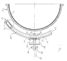
- Fig. 1 is a horizontal section through an inventive Perimeter shown, the screen 1 is hemispherical and on its inner surface has a projection surface 2.
- the subject looks into the middle of the screen, with his eye by a not shown in the embodiment Fixation mark is fixed.
- the screen 1 consists of a transparent or translucent material, this material has a relatively large light attenuation has, so that, as can be seen from FIG. 3, the rays reflected by the test mark 4 up to Back 3, where they are reflected again, are already subdued in their brightness, so that when they turn to the front, d. H. hit the screen 2 of the screen, are no longer perceived by the subject's eye. This avoids that the subject is circular Sees rings around the test mark.
- test mark 4 on the projection surface 2 of the screen 1 serve two diodes 9, 10 that you Emit light on a glass rod 8. From this glass rod the light hits a semi-transparent mirror 6, which is arranged at 45 ° in the beam path is. From this mirror, the light becomes the screen 1 guided via an imaging optics 5, which is an exact Defined test mark 4 generated. That from the test mark 4 reflected light reaches through the semi-translucent Mirror 6 is a photocell 7 with which the brightness of the reflected light is measured. The measurement signal is used to control the diodes 9, 10, so that the test mark 4 in its brightness predefined values can be adjusted exactly.
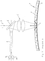
- the entire imaging optics 5, the semi-transparent Mirror 6, the photocell 7, the glass rod 8, the for Homogenization of the light of the diodes 9, 10 is used, and the diodes 9, 10 are attached to a swivel arm 11, which is attached to a mounting plate 18.
- the swivel arm 11 is held by three guide rollers 19, 20, 21, each on one side of the Swivel arm 11 are arranged. Will the swivel arm 11, which is adapted to the contour of the bowl, that this is an equidistant in all its areas Has a distance from the projection surface 2 of the screen 1, moved, so the light source has to generate the test mark 4 always the same distance and orientation to the test area.
- the swivel arm 11 can be within the guide rollers 19, 20, 21 are moved so that a light source unit fixedly arranged on the swivel arm 11 9, 10 moved parallel to the screen surface becomes.
- the swivel arm 11 in turn is on a mounting plate 18 attached to which the guide rollers 19, 20, 21, the deflection rollers 22, 23 and the drive gear 24 are attached.
- This mounting plate is in turn attached to an axis 12 on the frame 14 of the device is attached.
- This axis is perpendicular to Projection screen 2 of the screen arranged, d. H. the The axis extends through the center of the screen. If this axis 12 by the motor 13th rotated, so the light source 9, 10 and thus the test mark 4 moves on a circle.
- the exemplary embodiment there is only one light source shown, but it is also possible to use multiple light sources to be arranged on the swivel arm, so that also Points of light at different points on the screen without shifting the light source or one Rotation of the axis can be generated.
- the light source 9, 10 advantageously consists of two or three diodes, here either when using two diodes blue and yellow diodes can be used or yellow when using three diodes, red and green diodes.
- the number of diodes can also be multiplied, or else laser diodes are used, the one can emit increased light energy.
- the advantage of Use of diodes is that by mixing a white test mark for the light of the diodes or else any colored test mark on the projection surface can be generated. So it's color studies, e.g. B. blue perimetry possible. With the blue perimetry and a yellow environment can be different Diseases such as B. glaucoma, diabetic Detect retinopathy earlier than in a white test mark is the case.
- An aged diode system is preferred as the projection system related. Changes in brightness become advantageous realized by frequency time modulation. Of further it is easily possible with the invention Device different test mark sizes to offer, with usual test mark sizes 10 angular minutes or have 30 angular minutes.
- the fixation of the eye can be done in the usual way a fixed fixation mark can be reached, or else a segment image is created directly via a CCD camera appears, with a not shown adjustable chin rest to be examined Eye can be positioned exactly on the center of the ball.
- an optical fiber line can be used by a centrally placed light source is fed.
- a filter system or a gray wedge can be turned on corresponding brightness gradation in a simple manner to obtain.
- a locking system can also be provided be used to display the test mark in time To be able to offer distances.
Landscapes
- Life Sciences & Earth Sciences (AREA)
- Health & Medical Sciences (AREA)
- Medical Informatics (AREA)
- Biophysics (AREA)
- Ophthalmology & Optometry (AREA)
- Engineering & Computer Science (AREA)
- Biomedical Technology (AREA)
- Heart & Thoracic Surgery (AREA)
- Physics & Mathematics (AREA)
- Molecular Biology (AREA)
- Surgery (AREA)
- Animal Behavior & Ethology (AREA)
- General Health & Medical Sciences (AREA)
- Public Health (AREA)
- Veterinary Medicine (AREA)
- Eye Examination Apparatus (AREA)
Abstract
Description
- Fig. 1
- einen Schnitt durch ein erfindungsgemäß ausgebildetes Gerät,
- Fig. 2
- einen um 90 ° hierzu verlaufenden Schnitt und
- Fig. 3
- die Einzelheit X in Fig. 1 in vergrößertem Maßstab.
Claims (16)
- Gerät zur Prüfung des Gesichtsfeldes des menschlichen Auges mit einem schalenförmigen Schirm, auf dessen Grund eine oder mehrere Testmarken projiziert werden, dadurch gekennzeichnet, daß der Schirm (1) aus einem transparenten Material besteht, daß die Lichtquelle(n) (9, 10) für die Testmarke(n) (4) auf einem der Kontur des Schirmes (1) mit äquidistantem Abstand folgenden und auf dessen Rückseite liegenden Schwenkarm (11) angeordnet ist (sind), daß die Testmarke(n) (4) von der Rückseite (3) her auf den Schirm (1) etwa senkrecht zur Flächennormalen projiziert wird (werden) und daß die Lichtquelle(n) und damit die Testmarke(n) (4) flächig über dessen Rückseite verfahrbar angeordnet ist (sind).
- Gerät nach Anspruch 1, dadurch gekennzeichnet, daß als Lichtquelle (9, 10) für die Testmarke (4) eine oder mehre LED's oder Laserdioden dienen.
- Gerät nach Anspruch 2, dadurch gekennzeichnet, daß entweder blaue und gelbe Dioden oder gelbe, rote und grüne Dioden eingesetzt werden, die jeweils eine Testmarke (4) beleuchten.
- Gerät nach Anspruch 2 oder 3, dadurch gekennzeichnet, daß zur Mischung des von den Dioden (9, 10) ausgehenden Lichtes ein Glasstab (8) dient.
- Gerät nach Anspruch 4, dadurch gekennzeichnet, daß der Glasstab (8) einen Durchmesser von ca. 2 mm aufweist.
- Gerät nach einem der Ansprüche 1 bis 5, dadurch gekennzeichnet, daß der Schirm (1) aus einem das Licht dämpfenden Material besteht.
- Gerät nach einem der Ansprüche 1 bis 6, dadurch gekennzeichnet, daß der Schwenkarm (11) um eine Achse (12) drehbar ist, die senkrecht zur Projektionsfiäche (2) des Schirmes (1) verläuft.
- Gerät nach Anspruch 7, dadurch gekennzeichnet, daß der Schwenkarm (11) parallel zur Projektionsfläche (2) des Schirmes (1) verschiebbar ist.
- Gerät nach Anspruch 7, dadurch gekennzeichnet, daß die Lichtquelle (9, 10) auf dem Schwenkarm (11) verschiebbar ist.
- Gerät nach Anspruch 8 oder 9, dadurch gekennzeichnet, daß der Schwenkarm (11) durch mindestens drei Führungsrollen (19, 20, 21) geführt ist, die auf einer mit der Drehachse (12) verbundenen Montageplatte (18) befestigt sind.
- Gerät nach Anspruch 10, dadurch gekennzeichnet, daß auf dem Schwenkarm (11) ein Zahnriemen (15) angeordnet ist, der an dem jeweiligen Ende (16, 17) des Schwenkarmes (11) befestigt ist, und daß der Zahnriemen (15) über zwei Umlenkrollen (22, 23) und ein Antriebszahnrad (24) geführt ist.
- Gerät nach einem der Ansprüche 1 bis 11, dadurch gekennzeichnet, daß der Schirm (1) auf seiner Innenseite beschichtet ist.
- Gerät nach einem der Ansprüche 1 bis 12, dadurch gekennzeichnet, daß die Dioden (9, 10) zur Erzeugung des Mischlichtes einzeln ansteuerbar ausgebildet sind.
- Gerät nach einem der Ansprüche 1 bis 13, dadurch gekennzeichnet, daß eine oder mehrere Fixiermarken in dem Schirm (1) vorgesehen sind.
- Gerät nach einem der Ansprüche 1 bis 14, dadurch gekennzeichnet, daß in dem Projektionsstrahl für die Testmarken (4) ein teildurchlässiger Spiegel (6) angeordnet ist und daß der ausgeblendete Strahlenanteil in seiner Lichtstärke erfaßt und z. B. zur Steuerung der Helligkeit der Testmarke (4) dient.
- Gerät nach Anspruch 15, dadurch gekennzeichnet, daß der teildurchlässige Spiegel (6) auf dem Schwenkarm (11) angeordnet ist.
Priority Applications (1)
| Application Number | Priority Date | Filing Date | Title |
|---|---|---|---|
| EP01114093A EP1132043A3 (de) | 1996-06-24 | 1997-05-02 | Gerät zur Prüfung des Gesichtsfeldes des menschlichen Auges |
Applications Claiming Priority (2)
| Application Number | Priority Date | Filing Date | Title |
|---|---|---|---|
| DE19625199 | 1996-06-24 | ||
| DE19625199 | 1996-06-24 |
Related Child Applications (2)
| Application Number | Title | Priority Date | Filing Date |
|---|---|---|---|
| EP01114093A Division EP1132043A3 (de) | 1996-06-24 | 1997-05-02 | Gerät zur Prüfung des Gesichtsfeldes des menschlichen Auges |
| EP01114093A Division-Into EP1132043A3 (de) | 1996-06-24 | 1997-05-02 | Gerät zur Prüfung des Gesichtsfeldes des menschlichen Auges |
Publications (3)
| Publication Number | Publication Date |
|---|---|
| EP0815789A2 true EP0815789A2 (de) | 1998-01-07 |
| EP0815789A3 EP0815789A3 (de) | 1998-01-14 |
| EP0815789B1 EP0815789B1 (de) | 2004-03-31 |
Family
ID=7797828
Family Applications (2)
| Application Number | Title | Priority Date | Filing Date |
|---|---|---|---|
| EP97107274A Expired - Lifetime EP0815789B1 (de) | 1996-06-24 | 1997-05-02 | Gerät zur Prüfung des Gesichtsfeldes des menschlichen Auges |
| EP01114093A Withdrawn EP1132043A3 (de) | 1996-06-24 | 1997-05-02 | Gerät zur Prüfung des Gesichtsfeldes des menschlichen Auges |
Family Applications After (1)
| Application Number | Title | Priority Date | Filing Date |
|---|---|---|---|
| EP01114093A Withdrawn EP1132043A3 (de) | 1996-06-24 | 1997-05-02 | Gerät zur Prüfung des Gesichtsfeldes des menschlichen Auges |
Country Status (5)
| Country | Link |
|---|---|
| US (1) | US5870169A (de) |
| EP (2) | EP0815789B1 (de) |
| JP (1) | JP3215357B2 (de) |
| DE (1) | DE59711461D1 (de) |
| ES (1) | ES2217348T3 (de) |
Cited By (1)
| Publication number | Priority date | Publication date | Assignee | Title |
|---|---|---|---|---|
| WO2021048509A1 (fr) * | 2019-09-13 | 2021-03-18 | E-Swin Developpement | Dispositif de mesure ophtalmologique polyvalent |
Families Citing this family (7)
| Publication number | Priority date | Publication date | Assignee | Title |
|---|---|---|---|---|
| US6068377A (en) * | 1999-05-14 | 2000-05-30 | Visionrx.Com, Inc. | Visual test utilizing color frequency doubling |
| US6729728B2 (en) | 2001-06-14 | 2004-05-04 | Carl Zeiss Meditec, Inc. | Back projection visual field tester |
| US6572229B2 (en) | 2001-06-14 | 2003-06-03 | Carl Zeiss, Inc. | Back projection visual field tester |
| EP1407710B1 (de) * | 2002-10-08 | 2005-08-10 | Inami & Co., Ltd. | Computer gesteuertes Perimetriesystem |
| RU2285440C2 (ru) * | 2004-12-06 | 2006-10-20 | Ольга Александровна Румянцева | Устройство для исследования поля зрения |
| RU2376926C1 (ru) * | 2008-06-17 | 2009-12-27 | Федеральное государственное учреждение "Межотраслевой начно-технический комплекс "Микрохирургия глаза" имени академика С.Н. Федорова Федерального агентства по высокотехнологичной медицинской помощи" | Устройство для исследования полей зрения |
| JP5582503B2 (ja) * | 2010-09-24 | 2014-09-03 | 学校法人麻布獣医学園 | 視軸・視野の測定方法およびその測定装置 |
Family Cites Families (9)
| Publication number | Priority date | Publication date | Assignee | Title |
|---|---|---|---|---|
| DE185715C (de) * | ||||
| DE650912C (de) * | 1935-05-11 | 1937-10-04 | Paul Niederhoff Dr | Perimeter |
| CH264664A (de) * | 1948-02-19 | 1949-10-31 | M J Purtschert & Co Ag Luzern | Verfahren zur Ausmessung des Gesichtsfeldes des Auges und Vorrichtung zur Ausübung des Verfahrens. |
| US2803990A (en) * | 1951-08-01 | 1957-08-27 | Bonna Macknight | Optical perimeter |
| FR1078181A (fr) * | 1953-06-09 | 1954-11-16 | Périmètre pour l'examen du champ visuel | |
| US3947099A (en) * | 1975-01-02 | 1976-03-30 | American Optical Corporation | Solid state color anomaloscope |
| IT1053342B (it) * | 1975-02-22 | 1981-08-31 | Rodenstock Optik G | Apparecchio d esame oftalmico perimetrico |
| US4561738A (en) * | 1982-10-26 | 1985-12-31 | Humphrey Instruments, Inc. | Field tester |
| DD227880A1 (de) * | 1984-10-31 | 1985-10-02 | Ilmenau Tech Hochschule | Anordnung zur reizmarkenerzeugung bei der automatischen perimetrie |
-
1997
- 1997-05-02 EP EP97107274A patent/EP0815789B1/de not_active Expired - Lifetime
- 1997-05-02 ES ES97107274T patent/ES2217348T3/es not_active Expired - Lifetime
- 1997-05-02 EP EP01114093A patent/EP1132043A3/de not_active Withdrawn
- 1997-05-02 DE DE59711461T patent/DE59711461D1/de not_active Expired - Lifetime
- 1997-06-19 US US08/874,375 patent/US5870169A/en not_active Expired - Lifetime
- 1997-06-24 JP JP16716397A patent/JP3215357B2/ja not_active Expired - Lifetime
Cited By (6)
| Publication number | Priority date | Publication date | Assignee | Title |
|---|---|---|---|---|
| WO2021048509A1 (fr) * | 2019-09-13 | 2021-03-18 | E-Swin Developpement | Dispositif de mesure ophtalmologique polyvalent |
| FR3100704A1 (fr) * | 2019-09-13 | 2021-03-19 | E-Swin Developpement | Dispositif de mesure ophtalmologique polyvalent |
| CN114401662A (zh) * | 2019-09-13 | 2022-04-26 | 埃-斯温发展公司 | 多用途眼科测量装置 |
| US12279815B2 (en) | 2019-09-13 | 2025-04-22 | E-Swin Developpement | Multipurpose ophthalmological measuring device |
| CN114401662B (zh) * | 2019-09-13 | 2025-05-09 | 埃-斯温发展公司 | 多用途眼科测量装置 |
| AU2020347520B2 (en) * | 2019-09-13 | 2025-12-04 | E-Swin Developpement | Multipurpose ophthalmological measuring device |
Also Published As
| Publication number | Publication date |
|---|---|
| ES2217348T3 (es) | 2004-11-01 |
| JP3215357B2 (ja) | 2001-10-02 |
| US5870169A (en) | 1999-02-09 |
| DE59711461D1 (de) | 2004-05-06 |
| JPH1057313A (ja) | 1998-03-03 |
| EP0815789A3 (de) | 1998-01-14 |
| EP1132043A3 (de) | 2004-10-20 |
| EP1132043A2 (de) | 2001-09-12 |
| EP0815789B1 (de) | 2004-03-31 |
Similar Documents
| Publication | Publication Date | Title |
|---|---|---|
| DE68908782T2 (de) | Augenbewegungsinspektionsgerät. | |
| DE2536801A1 (de) | Vorrichtung zur messung der groesse einer augenpupille | |
| EP2436305B1 (de) | Sehtestgerät | |
| EP0363610B1 (de) | Vorrichtung zum Prüfen visueller Funktionen eines menschlichen Auges | |
| DE3503271A1 (de) | Vorrichtung zum messen der zum anbringen von brillenglaesern in einem brillengestell erforderlichen parameter | |
| EP0492044B1 (de) | Sehtestgerät | |
| DE3048038C2 (de) | Vorrichtung zur Prüfung des Gesichtsfeldes | |
| DE19501415C2 (de) | Sehtestgerät | |
| EP0815789B1 (de) | Gerät zur Prüfung des Gesichtsfeldes des menschlichen Auges | |
| CH688304A5 (de) | Ophthalmologisches Geraet. | |
| DE2939940C2 (de) | Augenprüfgerät zur Darbietung von Sehtests | |
| EP0830838B1 (de) | Sehtestgerät | |
| WO2010089062A1 (de) | Anordnung zur darstellung einer fixiermarke für ophtalmologische geräte mittels difffraktiver optischer elemente | |
| DE19540802A1 (de) | Vorrichtung und Verfahren zur Prüfung von Sehfunktionen | |
| DE2148417A1 (de) | Ophthalmometer | |
| DE2422553C3 (de) | Blickzielanordnung für Augenuntersuchungsgeräte | |
| DE1222708B (de) | Einrichtung zur Gesichtsfeldmessung | |
| DE102005034619B3 (de) | Verfahren und Vorrichtung zum Prüfen des Nachtsehens | |
| WO1998013665A1 (de) | Vorrichtung zum vermessen der erhebung einer oberfläche, insbesonder der netzhaut | |
| DE10037375C2 (de) | Vorrichtung zur Durchführung von Einzelmessungen der jeweiligen Beweglichkeit der beiden Augen eines Probanden | |
| DE2828532A1 (de) | Elektronisch ansteuerbare reizeinrichtung zur pruefung von augenfolgebewegungen | |
| DE2922646C2 (de) | Vorrichtung zur Messung der Angenbewegung | |
| DE2356778C3 (de) | Perimetergerät zur Bestimmung der Sehfeldgrenzen | |
| EP0823237A1 (de) | Videomessung der Position oder der Bewegung von Augen | |
| DE10134458A1 (de) | Messsystem zum Messen der optischen Eigenschaften eines Objekts und insbesondere dafür vorgesehener Messkopf |
Legal Events
| Date | Code | Title | Description |
|---|---|---|---|
| PUAI | Public reference made under article 153(3) epc to a published international application that has entered the european phase |
Free format text: ORIGINAL CODE: 0009012 |
|
| PUAL | Search report despatched |
Free format text: ORIGINAL CODE: 0009013 |
|
| AK | Designated contracting states |
Kind code of ref document: A2 Designated state(s): DE ES FR GB IT |
|
| AK | Designated contracting states |
Kind code of ref document: A3 Designated state(s): DE ES FR GB IT |
|
| 17P | Request for examination filed |
Effective date: 19980204 |
|
| 17Q | First examination report despatched |
Effective date: 20030401 |
|
| GRAP | Despatch of communication of intention to grant a patent |
Free format text: ORIGINAL CODE: EPIDOSNIGR1 |
|
| GRAS | Grant fee paid |
Free format text: ORIGINAL CODE: EPIDOSNIGR3 |
|
| GRAA | (expected) grant |
Free format text: ORIGINAL CODE: 0009210 |
|
| AK | Designated contracting states |
Kind code of ref document: B1 Designated state(s): DE ES FR GB IT |
|
| REG | Reference to a national code |
Ref country code: GB Ref legal event code: FG4D Free format text: NOT ENGLISH |
|
| REF | Corresponds to: |
Ref document number: 59711461 Country of ref document: DE Date of ref document: 20040506 Kind code of ref document: P |
|
| GBT | Gb: translation of ep patent filed (gb section 77(6)(a)/1977) |
Effective date: 20040510 |
|
| REG | Reference to a national code |
Ref country code: ES Ref legal event code: FG2A Ref document number: 2217348 Country of ref document: ES Kind code of ref document: T3 |
|
| ET | Fr: translation filed | ||
| PLBE | No opposition filed within time limit |
Free format text: ORIGINAL CODE: 0009261 |
|
| STAA | Information on the status of an ep patent application or granted ep patent |
Free format text: STATUS: NO OPPOSITION FILED WITHIN TIME LIMIT |
|
| 26N | No opposition filed |
Effective date: 20050104 |
|
| REG | Reference to a national code |
Ref country code: FR Ref legal event code: PLFP Year of fee payment: 20 |
|
| PGFP | Annual fee paid to national office [announced via postgrant information from national office to epo] |
Ref country code: ES Payment date: 20160523 Year of fee payment: 20 Ref country code: GB Payment date: 20160523 Year of fee payment: 20 |
|
| PGFP | Annual fee paid to national office [announced via postgrant information from national office to epo] |
Ref country code: FR Payment date: 20160523 Year of fee payment: 20 Ref country code: IT Payment date: 20160524 Year of fee payment: 20 |
|
| PGFP | Annual fee paid to national office [announced via postgrant information from national office to epo] |
Ref country code: DE Payment date: 20160715 Year of fee payment: 20 |
|
| REG | Reference to a national code |
Ref country code: DE Ref legal event code: R071 Ref document number: 59711461 Country of ref document: DE |
|
| REG | Reference to a national code |
Ref country code: GB Ref legal event code: PE20 Expiry date: 20170501 |
|
| PG25 | Lapsed in a contracting state [announced via postgrant information from national office to epo] |
Ref country code: GB Free format text: LAPSE BECAUSE OF EXPIRATION OF PROTECTION Effective date: 20170501 |
|
| REG | Reference to a national code |
Ref country code: ES Ref legal event code: FD2A Effective date: 20180508 |
|
| PG25 | Lapsed in a contracting state [announced via postgrant information from national office to epo] |
Ref country code: ES Free format text: LAPSE BECAUSE OF EXPIRATION OF PROTECTION Effective date: 20170503 |