EP0814221A1 - Process for fabricating a concrete mast, apparatus for carrying out the process and mast obtained therefrom - Google Patents
Process for fabricating a concrete mast, apparatus for carrying out the process and mast obtained therefrom Download PDFInfo
- Publication number
- EP0814221A1 EP0814221A1 EP97109519A EP97109519A EP0814221A1 EP 0814221 A1 EP0814221 A1 EP 0814221A1 EP 97109519 A EP97109519 A EP 97109519A EP 97109519 A EP97109519 A EP 97109519A EP 0814221 A1 EP0814221 A1 EP 0814221A1
- Authority
- EP
- European Patent Office
- Prior art keywords
- mold
- elements
- concrete
- mast
- flanges
- Prior art date
- Legal status (The legal status is an assumption and is not a legal conclusion. Google has not performed a legal analysis and makes no representation as to the accuracy of the status listed.)
- Granted
Links
- 239000004567 concrete Substances 0.000 title claims abstract description 30
- 238000000034 method Methods 0.000 title claims abstract description 21
- 230000002787 reinforcement Effects 0.000 claims description 14
- 238000000605 extraction Methods 0.000 claims description 12
- 238000005119 centrifugation Methods 0.000 claims description 11
- 239000002184 metal Substances 0.000 claims description 11
- 238000004519 manufacturing process Methods 0.000 claims description 8
- 230000008878 coupling Effects 0.000 claims description 6
- 238000010168 coupling process Methods 0.000 claims description 6
- 238000005859 coupling reaction Methods 0.000 claims description 6
- 238000009415 formwork Methods 0.000 claims description 4
- 239000000463 material Substances 0.000 claims description 4
- 230000001464 adherent effect Effects 0.000 claims description 3
- 238000003754 machining Methods 0.000 claims description 2
- 239000011150 reinforced concrete Substances 0.000 claims 3
- 230000003014 reinforcing effect Effects 0.000 abstract 2
- 238000005266 casting Methods 0.000 abstract 1
- 239000004570 mortar (masonry) Substances 0.000 abstract 1
- 238000009416 shuttering Methods 0.000 abstract 1
- 239000011178 precast concrete Substances 0.000 description 3
- 238000005452 bending Methods 0.000 description 2
- 230000005540 biological transmission Effects 0.000 description 2
- 238000002347 injection Methods 0.000 description 2
- 239000007924 injection Substances 0.000 description 2
- 238000010521 absorption reaction Methods 0.000 description 1
- 230000007547 defect Effects 0.000 description 1
- 238000010008 shearing Methods 0.000 description 1
- 238000003860 storage Methods 0.000 description 1
- 239000011800 void material Substances 0.000 description 1
- 238000003466 welding Methods 0.000 description 1
Images


Classifications
-
- E—FIXED CONSTRUCTIONS
- E04—BUILDING
- E04H—BUILDINGS OR LIKE STRUCTURES FOR PARTICULAR PURPOSES; SWIMMING OR SPLASH BATHS OR POOLS; MASTS; FENCING; TENTS OR CANOPIES, IN GENERAL
- E04H12/00—Towers; Masts or poles; Chimney stacks; Water-towers; Methods of erecting such structures
- E04H12/16—Prestressed structures
-
- B—PERFORMING OPERATIONS; TRANSPORTING
- B28—WORKING CEMENT, CLAY, OR STONE
- B28B—SHAPING CLAY OR OTHER CERAMIC COMPOSITIONS; SHAPING SLAG; SHAPING MIXTURES CONTAINING CEMENTITIOUS MATERIAL, e.g. PLASTER
- B28B13/00—Feeding the unshaped material to moulds or apparatus for producing shaped articles; Discharging shaped articles from such moulds or apparatus
- B28B13/04—Discharging the shaped articles
- B28B13/06—Removing the shaped articles from moulds
-
- B—PERFORMING OPERATIONS; TRANSPORTING
- B28—WORKING CEMENT, CLAY, OR STONE
- B28B—SHAPING CLAY OR OTHER CERAMIC COMPOSITIONS; SHAPING SLAG; SHAPING MIXTURES CONTAINING CEMENTITIOUS MATERIAL, e.g. PLASTER
- B28B23/00—Arrangements specially adapted for the production of shaped articles with elements wholly or partly embedded in the moulding material; Production of reinforced objects
- B28B23/02—Arrangements specially adapted for the production of shaped articles with elements wholly or partly embedded in the moulding material; Production of reinforced objects wherein the elements are reinforcing members
- B28B23/18—Arrangements specially adapted for the production of shaped articles with elements wholly or partly embedded in the moulding material; Production of reinforced objects wherein the elements are reinforcing members for the production of elongated articles
-
- E—FIXED CONSTRUCTIONS
- E04—BUILDING
- E04H—BUILDINGS OR LIKE STRUCTURES FOR PARTICULAR PURPOSES; SWIMMING OR SPLASH BATHS OR POOLS; MASTS; FENCING; TENTS OR CANOPIES, IN GENERAL
- E04H12/00—Towers; Masts or poles; Chimney stacks; Water-towers; Methods of erecting such structures
- E04H12/02—Structures made of specified materials
- E04H12/12—Structures made of specified materials of concrete or other stone-like material, with or without internal or external reinforcements, e.g. with metal coverings, with permanent form elements
Definitions
- the subject of the present invention is a method for manufacturing concrete masts and a device for implementing this method.
- This invention also relates to concrete masts directly obtained by the implementation of said method.
- This method is particularly suitable for the manufacture of masts of a considerable length which cannot be manufactured in a single part, or of masts which, because of constraints inherent in their transport or their storage, must be made of several elements.
- Masts are known comprising at one of their ends a female cone intended to receive a male cone from one end of another mast, these cones being of corresponding precise dimensions so that, during the introduction of the male cone d 'an element in the female cone of another element, we obtain an assembly with the least play possible.
- the angle at the top of the cone is chosen to make a self-locking coupling.
- This technique which requires high dimensional precision of the male and female cones of the elements, can only be used, for precast concrete elements by centrifugation, if these cones are produced beforehand in precise molds and then incorporated into the structural element during its centrifugation. It is indeed impossible to obtain cones, and in particular female cones having the dimensional precision required by centrifugation.
- This technique because of the precision required, is too expensive for the production of precast concrete masts by centrifugation. It also has the disadvantage of requiring the welding of the metal reinforcements of the mast to those of the cone when the latter are put in place.
- Another technique for producing concrete masts either by centrifugation or by vibration on a vibrating table consists in using metal cones, respectively male and female, at the ends of the elements of the mast. These metal cones act as a lost mold and remain integrated into the elements constituting the mast after its manufacture and coupling. To reduce the production costs of such masts, these metal cones were made from rolled sheets with the disadvantage that these cones are not very precise. The two added elements are in contact with the joint and due to the imprecision it is necessary to fill the space between the female cone and the male cone by injecting concrete or any other curable material in order to guarantee the good transmission of the forces of bending and twisting.
- the object of the present invention is to obviate the drawbacks mentioned above and to offer a method of manufacturing structural elements for making concrete masts both by centrifugation and by vibration which does not require a lost mold and which allows a coupling of the different elements of the precise mast, without play and therefore without injection during assembly and which is capable of effectively transmitting the bending and shearing forces and twist.
- Another object of the invention relates to a device allowing the implementation of the method cited above and which is distinguished by the characteristics listed in claim 6.
- the invention also relates to the precast concrete masts directly obtained by said process.
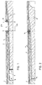
- Figure 1 illustrates two elements 1,2 shuttered and put in place on a bench to be concreted.
- Element 1 will be referenced as the female element and element 2 as the male element.
- the length of each element 1, 2 can be, for example, around twenty meters and their section can be circular, oval, elliptical or polygonal. To reduce the weight of these elements, they are generally hollow.
- the body of the elements 1,2 is in the form of a prismatic or cylindrical concrete tube which can be provided with longitudinal 3 and transverse 4 metallic reinforcements closed on themselves in order to reinforce the elements 1,2.
- a metal mold 5 in one piece is put in place before concreting between the two elements 1,2 of the mast. This mold 5 is in the form of a truncated cone closed at one of its ends.
- Two annular flanges 6,7 are arranged near the open end of the mold 5. These flanges 6,7 are directed outwards perpendicular to the axis of revolution of the truncated cone. At its opposite end, the mold 5 is closed by a bottom 8.
- a second disc 9 acts as a double bottom. The bottom of the mold 8 and the disc 9 are spaced apart by a distance substantially equivalent to that separating the two flanges 6,7 in the longitudinal direction. It is obvious that the double bottom of the mold can be produced in different ways such as for example being made up of the bottom 8 and of a plug made of a suitable material such as SAGEX (registered trademark) for example which would fill the space shown in the drawing between the bottom 8 and the disc 9.
- the flanges 6,7 are provided with holes distributed at regular intervals around their periphery. These holes 10 cooperate on the one hand with angular positioning devices of the two elements 1,2 of the mast and on the other hand with extraction devices to facilitate extraction of the mold after placing the concrete.
- FIG. 3 shows eight holes 10 distributed every 45 degrees cooperating with four angular positioning devices and four extraction devices distributed alternately around the periphery of the flange 7.
- the angular positioning device illustrated on a larger scale in Figure 4, consists of an assembly socket 11 communicating with the hole 10 and secured to a plate 12 bearing against the surface of the flanges 6,7 located towards the inside of the elements bodies 1,2.
- the ends of the longitudinal metal reinforcements 3 are welded against the external surface of the sockets 11.
- the socket 11 On the side of the female element 1, the socket 11 is extended by a formwork making it possible to provide a recess 13 in the body of the element 1.
- FIG. 2 illustrates the two elements 1, 2 of the mast after the placing of the concrete and after the mold 5 has been removed by means of the extraction devices, the operation of which will be explained below.
- the outer surface of the cone of the male element 2 comes into contact with the inner surface of the female cone of the element.
- the mold 5 is dimensioned and in particular the distance between the two flanges 6,7 so that the end of the male cone of the element 2 does not come into contact with the bottom of the female cone of the element 1 while the plates 12 ending the edge of the cones are also not in contact.
- the fact that these surfaces do not touch, once the elements have been assembled, prevents the perpendicularity of these surfaces from the axis of the cone has an influence on the alignment of the elements (1,2).
- the space remaining between these two annular surfaces 12 can be filled with a hard mass which will increase the compressed surface at this level.
- the angle of the cone is preferably minimum to facilitate the extraction of the mold 5, but can be chosen so that the assembly is self-locking.
- d m / sin ( ⁇ ) is an approximation and must be adjusted according to possible inaccuracies of the mold.
- Positioning studs 14 are housed in the sockets 11 thereby ensuring perfect angular positioning of the elements 1 and 2.
- the mold 5 is made of rolled sheets and therefore is not very precise. This fact, instead of being a drawback as in the case of a two-part mold, promotes the resumption of the torsional forces to which the mast is subjected. Indeed, the fact that the section of the conical mold 5 is not perfectly round promotes the absorption of torsional forces, the defects on one side of the mold being found on the other. It should be noted that this fact can be promoted by giving the section of the mold 5 a slightly oval or elliptical shape. It is also possible to produce the mold 5 by precise machining in a metal or plastic part.
- FIG. 5 illustrates the detail of the extraction devices located on the periphery of the flanges 6, 7 alternating with the positioning devices. They consist of a nut 15 welded to the external surface of the flanges 6,7. A bolt 16 bears in the service position against the stop plates 12 located on the annular surfaces of the male and female cones. When the concrete has been placed and set, it suffices to screw the bolts 16 to move the mold 5 away from the cones thus obtained.
- the bolts 16 cooperating with the nuts 15 can be replaced by hydraulic cylinders.
- FIG. 6 illustrates the positioning devices in the case of a mast comprising prestressing reinforcements 17. These prestressing reinforcements are as illustrated in the drawing, anchored at each end of the mast and tensioned. In this case, the flanges 6,7 have additional holes allowing the passage of these frames 17. It is also possible to provide that these prestressing frames 17 are anchored using a mechanical device provided on the stop plates and tensioned at each end of the mast .
- the method of manufacturing a concrete mast comprises the following steps. First of all, it involves placing the formwork on a concreting bench of at least two elements constituting the mast. It is obvious that, depending on the total length of the mast, more than two elements may be necessary to obtain the desired length.
- a metal mold is positioned in one piece at the junction of two elements. This mold is in the form of a truncated cone open at one of its ends and has a bottom 8 at the other end. At its open end, the mold has two annular flanges 6,7 parallel and substantially perpendicular to its axis of revolution. The mold also has a disc 9 parallel to the bottom 8 which acts as a double bottom.
- the longitudinal distance separating the bottom 8 of the disc 9 is slightly greater than the longitudinal spacing of the flanges 6,7.
- the distance between the two flanges 6,7 which depends on the thickness of the mold as well as the opening angle of the cone, is determined so that, once placed one on the other, the two elements s' fit together perfectly and come into contact only through their conical surfaces. Once the elements are in place as described above, the concrete is put in place.
- This concrete placement can be done in two different ways. We can first put the concrete in place by vibration by placing the bench on a vibrating table for example. Once the concrete has been poured, it suffices to remove the mold 5 by acting on the extraction devices arranged on the flanges 6,7 of the mold 5.
- the two elements are coupled 1,2 thus obtained.
- the fact of using a one-piece mold provided with positioning devices guarantees that the male cone of element 2 will adapt perfectly to the female cone receiving it from element 1, thereby allowing correct transmission of forces. of flexion and torsion.
- the concrete can be placed by centrifugation. In the case of concreting by centrifugation, an additional step is necessary before the extraction of the mold 5. Indeed during centrifugation there will be created a vacuum located between the outer surface of the conical mold 5 and the female cone. This void will be filled before removing the mold by injecting concrete or any other material which can be hardened by two injection holes made in the body of the female element 1.
- the prestressing reinforcements can be produced by the technique of adherent wires, these wires then being linked to the concrete, or by strands at the terminals which, once energized, are coupled to the ends of the mast portions, for example to the stop plates 12 .
Abstract
Description
La présente invention a pour objet un procédé de fabrication de mâts en béton ainsi qu'un dispositif pour la mise en oeuvre de ce procédé. Cette invention concerne également les mâts en béton directement obtenus par la mise en oeuvre dudit procédé. Ce procédé est particulièrement adapté à la fabrication de mâts d'une longueur importante qui ne peuvent être fabriqués en une seule partie, ou de mâts qui, à cause de contraintes inhérentes à leur transport ou leur stockage, doivent être réalisés en plusieurs éléments.The subject of the present invention is a method for manufacturing concrete masts and a device for implementing this method. This invention also relates to concrete masts directly obtained by the implementation of said method. This method is particularly suitable for the manufacture of masts of a considerable length which cannot be manufactured in a single part, or of masts which, because of constraints inherent in their transport or their storage, must be made of several elements.
On connaît des mâts comportant à l'une de leurs extrémités un cône femelle destiné à recevoir un cône mâle d'une extrémité d'un autre mât, ces cônes étant de dimensions précises correspondantes pour que, lors de l'introduction du cône mâle d'un élément dans le cône femelle d'un autre élément, on obtienne un assemblage avec le moins de jeu possible. L'angle au sommet du cône est choisi pour réaliser un accouplement autobloquant. Cette technique qui nécessite une grande précision dimensionnelle des cônes mâle et femelle des éléments ne peut être utilisée, pour des éléments préfabriqués en béton par centrifugation, que si ces cônes sont fabriqués préalablement dans des moules précis puis incorporés à l'élément de structure lors de sa centrifugation. Il est en effet impossible d'obtenir des cônes, et notamment des cônes femelles présentant la précision dimensionnelle requise par centrifugation. Cette technique, du fait de la précision requise, est trop onéreuse pour la production de mâts préfabriqués en béton par centrifugation. Elle présente encore l'inconvénient de nécessiter la soudure des armatures métalliques du mât à celles du cône lors de la mise en place de ces derniers.Masts are known comprising at one of their ends a female cone intended to receive a male cone from one end of another mast, these cones being of corresponding precise dimensions so that, during the introduction of the male cone d 'an element in the female cone of another element, we obtain an assembly with the least play possible. The angle at the top of the cone is chosen to make a self-locking coupling. This technique, which requires high dimensional precision of the male and female cones of the elements, can only be used, for precast concrete elements by centrifugation, if these cones are produced beforehand in precise molds and then incorporated into the structural element during its centrifugation. It is indeed impossible to obtain cones, and in particular female cones having the dimensional precision required by centrifugation. This technique, because of the precision required, is too expensive for the production of precast concrete masts by centrifugation. It also has the disadvantage of requiring the welding of the metal reinforcements of the mast to those of the cone when the latter are put in place.
Une autre technique de production de mâts en béton soit par centrifugation soit par vibrage sur une table vibrante consiste à utiliser des cônes métalliques respectivement mâle et femelle aux extrémités des éléments du mât. Ces cônes métalliques font office de moule perdu et restent intégrés aux éléments constituant le mât après sa fabrication et son accouplement. Pour diminuer les coûts de production de tels mâts, on a réalisé ces cônes métalliques en tôles roulées avec l'inconvénient que ces cônes ne sont pas très précis. Les deux éléments rapportés sont en contact au joint et du fait de l'imprécision il est nécessaire de remplir l'espace entre le cône femelle et le cône mâle en injectant du béton ou toute autre matière durcissable afin de garantir la bonne transmission des efforts de flexion et torsion.Another technique for producing concrete masts either by centrifugation or by vibration on a vibrating table consists in using metal cones, respectively male and female, at the ends of the elements of the mast. These metal cones act as a lost mold and remain integrated into the elements constituting the mast after its manufacture and coupling. To reduce the production costs of such masts, these metal cones were made from rolled sheets with the disadvantage that these cones are not very precise. The two added elements are in contact with the joint and due to the imprecision it is necessary to fill the space between the female cone and the male cone by injecting concrete or any other curable material in order to guarantee the good transmission of the forces of bending and twisting.
Le but de la présente invention est d'obvier aux inconvénients cités précédemment et d'offrir un procédé de fabrication d'éléments de structure pour réaliser des mâts en béton aussi bien par centrifugation que par vibrage qui ne nécessite pas de moule perdu et qui permette un accouplement des différents éléments du mât précis, sans jeu et donc sans injection lors du montage et qui soit capable de transmettre efficacement les efforts de flexion, de cisaillement et de torsion.The object of the present invention is to obviate the drawbacks mentioned above and to offer a method of manufacturing structural elements for making concrete masts both by centrifugation and by vibration which does not require a lost mold and which allows a coupling of the different elements of the precise mast, without play and therefore without injection during assembly and which is capable of effectively transmitting the bending and shearing forces and twist.
Ce but est atteint par un procédé tel que défini par les étapes énumérées à la revendication 1.This object is achieved by a method as defined by the steps listed in
Un autre objet de l'invention concerne un dispositif permettant la mise en oeuvre du procédé cité précédemment et qui se distingue par les caractéristiques énumérées à la revendication 6.Another object of the invention relates to a device allowing the implementation of the method cited above and which is distinguished by the characteristics listed in
L'invention concerne également les mâts en béton préfabriqués directement obtenus par ledit procédé.The invention also relates to the precast concrete masts directly obtained by said process.
L'invention va maintenant être décrite schématiquement et à titre d'exemple en référence au dessin annexé dans lequel:
- La figure 1 représente en plan deux éléments coffrés ainsi que le moule permettant de réaliser les cônes mâle et femelle.
- La figure 2 représente en plan les deux éléments assemblés une fois le moule retiré.
- La figure 3 est une coupe selon la ligne A-A de la figure 1.
- La figure 4 illustre les dispositifs de positionnement répartis sur les collerettes du moule illustrés à la figure 1.
- La figure 5 est une vue des dispositifs d'extraction permettant d'enlever le moule après la mise en place du béton.
- La figure 6 est une vue similaire à celle de la figure 4, le mât comportant des armatures de précontrainte.
- Figure 1 shows in plan two formwork elements and the mold for making the male and female cones.
- Figure 2 shows in plan the two elements assembled once the mold removed.
- Figure 3 is a section along the line AA in Figure 1.
- FIG. 4 illustrates the positioning devices distributed over the flanges of the mold illustrated in FIG. 1.
- Figure 5 is a view of the extraction devices for removing the mold after placing the concrete.
- Figure 6 is a view similar to that of Figure 4, the mast having prestressing frames.
La figure 1 illustre deux éléments 1,2 coffrés et mis en place sur un banc pour être bétonnés. L'élément 1 sera référencé comme l'élément femelle et l'élément 2 comme l'élément mâle. La longueur de chaque élément 1,2 peut être par exemple d'une vingtaine de mètres et leur section être circulaire, ovale, elliptique ou polygonale. Pour diminuer le poids de ces éléments, ils sont généralement creux. Ainsi le corps des éléments 1,2 se présente sous la forme d'un tube prismatique ou cylindrique en béton qui peut être munis d'armatures métalliques longitudinales 3 et transversales 4 fermées sur elles-mêmes afin de renforcer les éléments 1,2. Un moule métallique 5 en une seule pièce est mis en place avant bétonnage entre les deux éléments 1,2 du mât. Ce moule 5 se présente sous la forme d'un tronc de cône fermé à l'une de ses extrémités. Deux collerettes annulaires 6,7 sont agencées à proximité de l'extrémité ouverte du moule 5. Ces collerettes 6,7 sont dirigées vers l'extérieur perpendiculairement à l'axe de révolution du tronc de cône. A son extrémité opposée, le moule 5 est fermé par un fond 8. Un deuxième disque 9 fait office de double fond. Le fond du moule 8 et le disque 9 sont espacés d'une distance sensiblement équivalente à celle séparant les deux collerettes 6,7 dans le sens longitudinal. Il est évident que le double fond du moule peut être réalisé de différentes façons comme par exemple être constitué du fond 8 et d'un bouchon en une matière adaptée comme du SAGEX (marque déposée) par exemple qui remplirait l espace représenté au dessin entre le fond 8 et le disque 9. Les collerettes 6,7 sont pourvues de trous répartis à intervalles réguliers sur leur pourtour. Ces trous 10 coopèrent d'une part avec des dispositifs de positionnement angulaires des deux éléments 1,2 du mât et d'autre part avec des dispositifs d'extraction permettant de faciliter l'extraction du moule après la mise en place du béton. On voit sur la figure 3, huit trous 10 répartis tous les 45 degrés coopérant avec quatre dispositifs de positionnement angulaires et quatre dispositifs d'extraction répartis en alternance sur le pourtour de la collerette 7.Figure 1 illustrates two
Le dispositif de positionnement angulaire, illustré à plus grande échelle à la figure 4, est constitué d'une douille d'assemblage 11 communiquant avec le trou 10 et solidaire d'une plaque 12 prenant appui contre la surface des collerettes 6,7 situées vers l'intérieur des corps des éléments 1,2. Les extrémités des armatures métalliques longitudinales 3 sont soudées contre la surface extérieure des douilles 11. Du côté de l'élément femelle 1, la douille 11 se prolonge par un coffrage permettant de ménager un évidement 13 dans le corps de l'élément 1.The angular positioning device, illustrated on a larger scale in Figure 4, consists of an
La figure 2 illustre les deux éléments 1,2 du mât après la mise en place du béton et après que l'on ait retiré le moule 5 au moyen des dispositifs d'extraction dont le fonctionnement sera explicité ci-après. La surface extérieure du cône de l'élément mâle 2 vient au contact de la surface interne du cône femelle de l'élément. On notera que le moule 5 est dimensionné et notamment la distance entre les deux collerettes 6,7 de façon à ce que l'extrémité du cône mâle de l'élément 2 n'entre pas en contact avec le fond du cône femelle de l'élément 1 alors que les plaques 12 terminant le bord des cônes ne sont pas non plus en contact. Le fait que ces surfaces ne se touchent pas, une fois les éléments assemblés, évite que la perpendicularité de ces surfaces par rapport à l'axe du cône n'ait une influence sur l'alignement des éléments (1,2). Afin d'augmenter la résistance de l'accouplement à la base du cône, l'espace restant entre ces deux surfaces annulaires 12 peut être rempli d une masse dure qui va augmenter la surface comprimée à ce niveau. Ainsi l'assemblage des deux éléments se fait uniquement par l'entrée en contact des surfaces coniques mâle et femelle. L'angle du cône est de préférence minimum pour faciliter l'extraction du moule 5, mais peut être choisi de manière à ce que l'assemblage soit autobloquant. En définissant par d la distance entre les deux collerettes annulaires 6,7, par m l'épaisseur du moule, et par α l'angle d'ouverture du cône, on obtient la relation approximative suivante : ![]()
![]()
![]()
![]()
Comme ces cônes ont été obtenus par la paroi d un seul et même moule et qu'ils sont assemblés dans une position angulaire déterminée ou indexée, les éventuelles irrégularités, excentricité etc. de ces cônes ne font qu'augmenter la rigidité de l'assemblage puisqu'ils correspondent exactement.As these cones were obtained by the wall of a single mold and they are assembled in a determined or indexed angular position, any irregularities, eccentricity etc. of these cones only increase the rigidity of the assembly since they correspond exactly.
Des goujons de positionnement 14 viennent se loger dans les douilles 11 assurant de ce fait un positionnement angulaire parfait des éléments 1 et 2. Pour des raisons économiques, le moule 5 est réalisé en tôles roulées et de ce fait n'est pas très précis. Ce fait, au lieu d'être un inconvénient comme dans le cas d'un moule en deux parties, favorise la reprise des efforts de torsion auquel le mât est soumis. En effet, le fait que la section du moule conique 5 ne soit pas parfaitement ronde favorise l'absorption des efforts de torsion, les défauts d'un côté du moule se retrouvant de l'autre. Il est à noter que l on peut favoriser ce fait en donnant à la section du moule 5 une forme légèrement ovale ou elliptique. Il est également possible de réaliser le moule 5 par usinage précis dans une pièce en métal ou en plastique.Positioning
La figure 5 illustre le détail des dispositifs d extraction situés sur le pourtour des collerettes 6,7 en alternance avec les dispositifs de positionnement. Ils sont constitués d'un écrou 15 soudé sur la surface externe des collerettes 6,7. Un boulon 16 prend appui en position de service contre les plaques d'arrêt 12 situées sur les surfaces annulaires des cônes mâle et femelle. Lorsque le béton a été mis en place et a fait prise, il suffit de visser les boulons 16 pour écarter le moule 5 des cônes ainsi obtenus.FIG. 5 illustrates the detail of the extraction devices located on the periphery of the
Dans une variante, les boulons 16 coopèrant avec les écrous 15 peuvent être remplacés par des vérins hydrauliques.Alternatively, the
La figure 6 illustre les dispositifs de positionnement dans le cas d'un mât comportant des armatures de précontrainte 17. Ces armatures de précontrainte sont comme illustré au dessin, ancrées à chaque extrémité du mât et mises en tension. Dans ce cas, les collerettes 6,7 comportent des percements supplémentaires permettant le passage de ces armatures 17. Il est également possible de prévoir que ces armatures de précontrainte 17 soient ancrées à l'aide d'un dispositif mécanique prévu sur les plaques d'arrêt et mises en tension à chaque extrémité du mât.FIG. 6 illustrates the positioning devices in the case of a mast comprising
Le procédé de fabrication d'un mât en béton selon la présente invention comporte les étapes suivantes. Il s'agit tout d'abord de la mise en place du coffrage sur un banc de bétonnage d'au moins deux éléments constituant le mât. Il est évident qu'en fonction de la longueur totale du mât plus de deux éléments peuvent être nécessaires pour obtenir la longueur voulue. Après mise en place des coffrages et armatures métalliques longitudinales et transversales constituant la structure du mât, on positionne un moule métallique en une seule pièce à la jonction de deux éléments. Ce moule se présente sous la forme d'un tronc de cône ouvert à l'une de ses extrémités et comporte un fond 8 à l'autre extrémité. A son extrémité ouverte, le moule présente deux collerettes annulaires 6,7 parallèles et sensiblement perpendiculaires à son axe de révolution. Le moule comporte encore un disque 9 parallèle au fond 8 qui fait office de double fond.The method of manufacturing a concrete mast according to the present invention comprises the following steps. First of all, it involves placing the formwork on a concreting bench of at least two elements constituting the mast. It is obvious that, depending on the total length of the mast, more than two elements may be necessary to obtain the desired length. After setting up the longitudinal and transverse metal forms and reinforcements constituting the mast structure, a metal mold is positioned in one piece at the junction of two elements. This mold is in the form of a truncated cone open at one of its ends and has a bottom 8 at the other end. At its open end, the mold has two
La distance longitudinale séparant le fond 8 du disque 9 est légèrement supérieure à l'espacement longitudinal des collerettes 6,7. La distance entre les deux collerettes 6,7 qui dépend de l'épaisseur du moule ainsi que de l'angle d'ouverture du cône, est déterminée afin que, une fois mis l'un sur l'autre, les deux éléments s'emboîtent parfaitement et n'entrent en contact que par leurs surfaces coniques. Une fois les éléments mis en place comme décrit précédemment, on procède à la mise en place du béton. Cette mise en place du béton peut s'effectuer de deux façons différentes. On peut tout d'abord mettre le béton en place par vibrage en disposant le banc sur une table vibrante par exemple. Une fois le béton coulé, il suffit de retirer le moule 5 en agissant sur les dispositifs d'extraction agencés sur les collerettes 6,7 du moule 5. Une fois le moule récupéré, on procède à l'accouplement des deux éléments 1,2 ainsi obtenus. Le fait d'utiliser un moule en une seule pièce muni de dispositifs de positionnement garantit que le cône mâle de l'élément 2 s'adaptera parfaitement au cône femelle le recevant de l'élément 1, permettant de ce fait une transmission correcte des efforts de flexion et de torsion. Dans une variante, le béton peut être mis en place par centrifugation. Dans le cas d'un bétonnage par centrifugation, une étape supplémentaire est nécessaire avant l'extraction du moule 5. En effet lors de la centrifugation il va se créer un vide situé entre la surface extérieure du moule conique 5 et le cône femelle. Ce vide sera remplit avant de retirer le moule par injection de béton ou de tout autre matériau durcissable par deux orifices d'injection pratiqués dans le corps de l'élément femelle 1.The longitudinal distance separating the bottom 8 of the disc 9 is slightly greater than the longitudinal spacing of the
Dans le cas de mâts comportant des armatures de précontrainte 17 traversant les collerettes 6,7, il est nécessaire de couper ces armatures au niveau des collerettes avant le démoulage du moule 5. Cette opération n'est pas nécessaire si les armatures de précontrainte sont ancrées dans les plaques 12 formant les flasques du cône.In the case of masts having
Les armatures de précontrainte peuvent être réalisées par la technique des fils adhérents, ces fils étant alors liés au béton, ou par des torons au bornes qui une fois mises sous tension sont accouplées aux extrémités des portions de mât par exemple aux plaques d'arrêt 12.The prestressing reinforcements can be produced by the technique of adherent wires, these wires then being linked to the concrete, or by strands at the terminals which, once energized, are coupled to the ends of the mast portions, for example to the
Claims (21)
Applications Claiming Priority (3)
| Application Number | Priority Date | Filing Date | Title |
|---|---|---|---|
| CH155496 | 1996-06-21 | ||
| CH1554/96 | 1996-06-21 | ||
| CH01554/96A CH691234A5 (en) | 1996-06-21 | 1996-06-21 | A method of manufacturing a concrete mast, the device for implementing this method and pole obtained by this method. |
Publications (2)
| Publication Number | Publication Date |
|---|---|
| EP0814221A1 true EP0814221A1 (en) | 1997-12-29 |
| EP0814221B1 EP0814221B1 (en) | 2002-09-18 |
Family
ID=4213136
Family Applications (1)
| Application Number | Title | Priority Date | Filing Date |
|---|---|---|---|
| EP97109519A Expired - Lifetime EP0814221B1 (en) | 1996-06-21 | 1997-06-12 | Process for fabricating a concrete mast, apparatus for carrying out the process and mast obtained therefrom |
Country Status (6)
| Country | Link |
|---|---|
| EP (1) | EP0814221B1 (en) |
| AT (1) | ATE224495T1 (en) |
| CH (1) | CH691234A5 (en) |
| DE (1) | DE69715524T2 (en) |
| DK (1) | DK0814221T3 (en) |
| ES (1) | ES2180856T3 (en) |
Families Citing this family (2)
| Publication number | Priority date | Publication date | Assignee | Title |
|---|---|---|---|---|
| ES2291053B1 (en) * | 2003-10-07 | 2009-03-01 | Romero Hormelec, S.A. | MANUFACTURE AND UNION SYSTEM OF HOLLOW CONCRETE POSTS OF REINFORCED AND / OR PRETENSED CONCRETE. |
| DE102006030400A1 (en) * | 2006-06-29 | 2008-01-03 | Pfleiderer Europoles Gmbh & Co. Kg | Transmission tower made of spun concrete |
Citations (3)
| Publication number | Priority date | Publication date | Assignee | Title |
|---|---|---|---|---|
| GB386108A (en) * | 1931-12-21 | 1933-01-12 | Pfistershammer Josef | Reinforced concrete pole |
| DE1434730A1 (en) * | 1963-11-12 | 1970-01-15 | Moll Kg Leonhard | Process for the production of steel or prestressed concrete masts consisting of several detachably connected parts and multi-part concrete mast produced according to this process |
| FR2367158A1 (en) * | 1976-10-05 | 1978-05-05 | Gram Sa | COUPLING DEVICE FOR REINFORCED OR PRE-STRESSED CONCRETE ELEMENT |
-
1996
- 1996-06-21 CH CH01554/96A patent/CH691234A5/en not_active IP Right Cessation
-
1997
- 1997-06-12 DE DE69715524T patent/DE69715524T2/en not_active Expired - Fee Related
- 1997-06-12 ES ES97109519T patent/ES2180856T3/en not_active Expired - Lifetime
- 1997-06-12 AT AT97109519T patent/ATE224495T1/en not_active IP Right Cessation
- 1997-06-12 EP EP97109519A patent/EP0814221B1/en not_active Expired - Lifetime
- 1997-06-12 DK DK97109519T patent/DK0814221T3/en active
Patent Citations (3)
| Publication number | Priority date | Publication date | Assignee | Title |
|---|---|---|---|---|
| GB386108A (en) * | 1931-12-21 | 1933-01-12 | Pfistershammer Josef | Reinforced concrete pole |
| DE1434730A1 (en) * | 1963-11-12 | 1970-01-15 | Moll Kg Leonhard | Process for the production of steel or prestressed concrete masts consisting of several detachably connected parts and multi-part concrete mast produced according to this process |
| FR2367158A1 (en) * | 1976-10-05 | 1978-05-05 | Gram Sa | COUPLING DEVICE FOR REINFORCED OR PRE-STRESSED CONCRETE ELEMENT |
Also Published As
| Publication number | Publication date |
|---|---|
| EP0814221B1 (en) | 2002-09-18 |
| ES2180856T3 (en) | 2003-02-16 |
| DE69715524T2 (en) | 2003-05-22 |
| DK0814221T3 (en) | 2003-01-27 |
| CH691234A5 (en) | 2001-05-31 |
| ATE224495T1 (en) | 2002-10-15 |
| DE69715524D1 (en) | 2002-10-24 |
Similar Documents
| Publication | Publication Date | Title |
|---|---|---|
| EP2140459B1 (en) | Container for transporting and/or storing nuclear materials, comprising a radiological shield made of lead cast onto a metal reinforcement | |
| WO1995025864A1 (en) | Panel for storage ponds | |
| FR3002956A1 (en) | PRECONTRATED MOLDED WALL AND METHOD OF MAKING SUCH A WALL | |
| FR2956871A1 (en) | METHOD AND TOOLING FOR THE IN SITU PRODUCTION OF A SANDWICH WALL COMPRISING TWO CONCRETE WALLS SEPARATED BY AN INSULATING PANEL | |
| EP0814221B1 (en) | Process for fabricating a concrete mast, apparatus for carrying out the process and mast obtained therefrom | |
| FR2473975A1 (en) | STEERING COLUMN WITHOUT WELDING, IN PARTICULAR FOR A MOTOR VEHICLE | |
| EP1068401A1 (en) | Pressurized liquid circulation duct and method for the production thereof | |
| CH677250A5 (en) | ||
| WO2019077257A1 (en) | Tool for the in situ construction of a sandwich wall, and method applying same | |
| EP1956156B1 (en) | Connector for joining two slabs of a wall with lost formwork. | |
| BE1003604A4 (en) | Post production process support and manufactured and posts. | |
| EP3867140B1 (en) | Floating module of a floating structure and method for joining such floating modules | |
| FR2587054A1 (en) | Method for building walls having the appearance of dry stone walls | |
| FR2653699A1 (en) | Process and device for closing holes left free by separating cones or tubes in concrete walls | |
| FR2539782A1 (en) | Arched beam in reinforced concrete | |
| FR2732714A1 (en) | Reinforced concrete panel for making tank and esp. slurry pit | |
| FR2634856A1 (en) | Concrete pipe | |
| FR2785932A1 (en) | Overhead power, lighting or telecommunications pole made of concrete or a similar material has two vertical parts tapering upward from wide base to narrow top | |
| FR2663878A1 (en) | Improvements to moulds for manufacturing elongate objects such as reinforced-concrete beams or posts | |
| FR2613657A1 (en) | Device for temporary holding, in a mould, of an element forming a sheath and method of manufacture of a mould product implementing such a device | |
| BE1006114A6 (en) | Method of manufacturing construction elements in concrete | |
| FR2524533A1 (en) | Spiral reinforced concrete pile - has screw-in point, with lateral pile carrying loops fixed to reinforcement | |
| EP3315681A1 (en) | Method for manufacturing a hollow element | |
| FR2634804A1 (en) | Method of inserting a prefabricated post in a very deep bore and post for the use of this method. | |
| BE633944A (en) |
Legal Events
| Date | Code | Title | Description |
|---|---|---|---|
| PUAI | Public reference made under article 153(3) epc to a published international application that has entered the european phase |
Free format text: ORIGINAL CODE: 0009012 |
|
| AK | Designated contracting states |
Kind code of ref document: A1 Designated state(s): AT BE CH DE DK ES FI FR GB IT LI NL SE |
|
| 17P | Request for examination filed |
Effective date: 19980130 |
|
| AKX | Designation fees paid |
Free format text: AT BE CH DE DK ES FI FR GB IT LI NL SE |
|
| RBV | Designated contracting states (corrected) |
Designated state(s): AT BE CH DE DK ES FI FR GB IT LI NL SE |
|
| 17Q | First examination report despatched |
Effective date: 20010814 |
|
| GRAG | Despatch of communication of intention to grant |
Free format text: ORIGINAL CODE: EPIDOS AGRA |
|
| GRAG | Despatch of communication of intention to grant |
Free format text: ORIGINAL CODE: EPIDOS AGRA |
|
| GRAH | Despatch of communication of intention to grant a patent |
Free format text: ORIGINAL CODE: EPIDOS IGRA |
|
| RAP1 | Party data changed (applicant data changed or rights of an application transferred) |
Owner name: GRAM S.A. |
|
| GRAH | Despatch of communication of intention to grant a patent |
Free format text: ORIGINAL CODE: EPIDOS IGRA |
|
| GRAA | (expected) grant |
Free format text: ORIGINAL CODE: 0009210 |
|
| AK | Designated contracting states |
Kind code of ref document: B1 Designated state(s): AT BE CH DE DK ES FI FR GB IT LI NL SE |
|
| REF | Corresponds to: |
Ref document number: 224495 Country of ref document: AT Date of ref document: 20021015 Kind code of ref document: T |
|
| REG | Reference to a national code |
Ref country code: GB Ref legal event code: FG4D Free format text: NOT ENGLISH |
|
| REG | Reference to a national code |
Ref country code: CH Ref legal event code: EP |
|
| REG | Reference to a national code |
Ref country code: CH Ref legal event code: NV Representative=s name: MICHELI & CIE INGENIEURS-CONSEILS |
|
| REF | Corresponds to: |
Ref document number: 69715524 Country of ref document: DE Date of ref document: 20021024 |
|
| GBT | Gb: translation of ep patent filed (gb section 77(6)(a)/1977) |
Effective date: 20021108 |
|
| REG | Reference to a national code |
Ref country code: DK Ref legal event code: T3 |
|
| REG | Reference to a national code |
Ref country code: ES Ref legal event code: FG2A Ref document number: 2180856 Country of ref document: ES Kind code of ref document: T3 |
|
| PGFP | Annual fee paid to national office [announced via postgrant information from national office to epo] |
Ref country code: NL Payment date: 20030530 Year of fee payment: 7 Ref country code: GB Payment date: 20030530 Year of fee payment: 7 |
|
| PGFP | Annual fee paid to national office [announced via postgrant information from national office to epo] |
Ref country code: AT Payment date: 20030603 Year of fee payment: 7 |
|
| PGFP | Annual fee paid to national office [announced via postgrant information from national office to epo] |
Ref country code: SE Payment date: 20030604 Year of fee payment: 7 |
|
| PGFP | Annual fee paid to national office [announced via postgrant information from national office to epo] |
Ref country code: FI Payment date: 20030605 Year of fee payment: 7 |
|
| PGFP | Annual fee paid to national office [announced via postgrant information from national office to epo] |
Ref country code: DK Payment date: 20030610 Year of fee payment: 7 |
|
| PGFP | Annual fee paid to national office [announced via postgrant information from national office to epo] |
Ref country code: BE Payment date: 20030612 Year of fee payment: 7 |
|
| PGFP | Annual fee paid to national office [announced via postgrant information from national office to epo] |
Ref country code: ES Payment date: 20030617 Year of fee payment: 7 |
|
| PLBE | No opposition filed within time limit |
Free format text: ORIGINAL CODE: 0009261 |
|
| STAA | Information on the status of an ep patent application or granted ep patent |
Free format text: STATUS: NO OPPOSITION FILED WITHIN TIME LIMIT |
|
| 26N | No opposition filed |
Effective date: 20030619 |
|
| PG25 | Lapsed in a contracting state [announced via postgrant information from national office to epo] |
Ref country code: GB Free format text: LAPSE BECAUSE OF NON-PAYMENT OF DUE FEES Effective date: 20040612 Ref country code: FI Free format text: LAPSE BECAUSE OF NON-PAYMENT OF DUE FEES Effective date: 20040612 Ref country code: AT Free format text: LAPSE BECAUSE OF NON-PAYMENT OF DUE FEES Effective date: 20040612 |
|
| PG25 | Lapsed in a contracting state [announced via postgrant information from national office to epo] |
Ref country code: SE Free format text: LAPSE BECAUSE OF NON-PAYMENT OF DUE FEES Effective date: 20040613 |
|
| PG25 | Lapsed in a contracting state [announced via postgrant information from national office to epo] |
Ref country code: ES Free format text: LAPSE BECAUSE OF NON-PAYMENT OF DUE FEES Effective date: 20040614 |
|
| PG25 | Lapsed in a contracting state [announced via postgrant information from national office to epo] |
Ref country code: DK Free format text: LAPSE BECAUSE OF NON-PAYMENT OF DUE FEES Effective date: 20040630 Ref country code: BE Free format text: LAPSE BECAUSE OF NON-PAYMENT OF DUE FEES Effective date: 20040630 |
|
| BERE | Be: lapsed |
Owner name: S.A. *GRAM Effective date: 20040630 |
|
| PG25 | Lapsed in a contracting state [announced via postgrant information from national office to epo] |
Ref country code: NL Free format text: LAPSE BECAUSE OF NON-PAYMENT OF DUE FEES Effective date: 20050101 |
|
| REG | Reference to a national code |
Ref country code: DK Ref legal event code: EBP |
|
| EUG | Se: european patent has lapsed | ||
| GBPC | Gb: european patent ceased through non-payment of renewal fee |
Effective date: 20040612 |
|
| EUG | Se: european patent has lapsed | ||
| NLV4 | Nl: lapsed or anulled due to non-payment of the annual fee |
Effective date: 20050101 |
|
| PG25 | Lapsed in a contracting state [announced via postgrant information from national office to epo] |
Ref country code: IT Free format text: LAPSE BECAUSE OF NON-PAYMENT OF DUE FEES;WARNING: LAPSES OF ITALIAN PATENTS WITH EFFECTIVE DATE BEFORE 2007 MAY HAVE OCCURRED AT ANY TIME BEFORE 2007. THE CORRECT EFFECTIVE DATE MAY BE DIFFERENT FROM THE ONE RECORDED. Effective date: 20050612 |
|
| REG | Reference to a national code |
Ref country code: ES Ref legal event code: FD2A Effective date: 20040614 |
|
| REG | Reference to a national code |
Ref country code: CH Ref legal event code: PUE Owner name: BETONTEC GRAM S.A. Free format text: GRAM S.A.#ROUTE DE LUCENS#1527 VILLENEUVE/LUCENS (CH) -TRANSFER TO- BETONTEC GRAM S.A.#ROUTE DE LUCENS#1527 VILLENEUVE (CH) |
|
| REG | Reference to a national code |
Ref country code: FR Ref legal event code: TP |
|
| PGFP | Annual fee paid to national office [announced via postgrant information from national office to epo] |
Ref country code: CH Payment date: 20060524 Year of fee payment: 10 |
|
| PGFP | Annual fee paid to national office [announced via postgrant information from national office to epo] |
Ref country code: DE Payment date: 20060616 Year of fee payment: 10 |
|
| PGFP | Annual fee paid to national office [announced via postgrant information from national office to epo] |
Ref country code: FR Payment date: 20060619 Year of fee payment: 10 |
|
| PG25 | Lapsed in a contracting state [announced via postgrant information from national office to epo] |
Ref country code: LI Free format text: LAPSE BECAUSE OF THE APPLICANT RENOUNCES Effective date: 20070601 Ref country code: CH Free format text: LAPSE BECAUSE OF THE APPLICANT RENOUNCES Effective date: 20070601 |
|
| REG | Reference to a national code |
Ref country code: CH Ref legal event code: PL |
|
| REG | Reference to a national code |
Ref country code: FR Ref legal event code: ST Effective date: 20080229 |
|
| PG25 | Lapsed in a contracting state [announced via postgrant information from national office to epo] |
Ref country code: DE Free format text: LAPSE BECAUSE OF NON-PAYMENT OF DUE FEES Effective date: 20080101 |
|
| PG25 | Lapsed in a contracting state [announced via postgrant information from national office to epo] |
Ref country code: FR Free format text: LAPSE BECAUSE OF NON-PAYMENT OF DUE FEES Effective date: 20070702 |