EP0813852A2 - Rollstuhl mit einer schwenkbaren Laufrolle - Google Patents
Rollstuhl mit einer schwenkbaren Laufrolle Download PDFInfo
- Publication number
- EP0813852A2 EP0813852A2 EP97201834A EP97201834A EP0813852A2 EP 0813852 A2 EP0813852 A2 EP 0813852A2 EP 97201834 A EP97201834 A EP 97201834A EP 97201834 A EP97201834 A EP 97201834A EP 0813852 A2 EP0813852 A2 EP 0813852A2
- Authority
- EP
- European Patent Office
- Prior art keywords
- swivel
- wheelchair
- castor
- limit
- range
- Prior art date
- Legal status (The legal status is an assumption and is not a legal conclusion. Google has not performed a legal analysis and makes no representation as to the accuracy of the status listed.)
- Withdrawn
Links
Images
Classifications
-
- B—PERFORMING OPERATIONS; TRANSPORTING
- B60—VEHICLES IN GENERAL
- B60B—VEHICLE WHEELS; CASTORS; AXLES FOR WHEELS OR CASTORS; INCREASING WHEEL ADHESION
- B60B33/00—Castors in general; Anti-clogging castors
- B60B33/02—Castors in general; Anti-clogging castors with disengageable swivel action, i.e. comprising a swivel locking mechanism
- B60B33/023—Castors in general; Anti-clogging castors with disengageable swivel action, i.e. comprising a swivel locking mechanism by using friction
-
- A—HUMAN NECESSITIES
- A61—MEDICAL OR VETERINARY SCIENCE; HYGIENE
- A61G—TRANSPORT, PERSONAL CONVEYANCES, OR ACCOMMODATION SPECIALLY ADAPTED FOR PATIENTS OR DISABLED PERSONS; OPERATING TABLES OR CHAIRS; CHAIRS FOR DENTISTRY; FUNERAL DEVICES
- A61G5/00—Chairs or personal conveyances specially adapted for patients or disabled persons, e.g. wheelchairs
- A61G5/10—Parts, details or accessories
-
- B—PERFORMING OPERATIONS; TRANSPORTING
- B60—VEHICLES IN GENERAL
- B60B—VEHICLE WHEELS; CASTORS; AXLES FOR WHEELS OR CASTORS; INCREASING WHEEL ADHESION
- B60B33/00—Castors in general; Anti-clogging castors
- B60B33/0002—Castors in general; Anti-clogging castors assembling to the object, e.g. furniture
- B60B33/0015—Castors in general; Anti-clogging castors assembling to the object, e.g. furniture characterised by adaptations made to castor
- B60B33/0021—Castors in general; Anti-clogging castors assembling to the object, e.g. furniture characterised by adaptations made to castor in the form of a mounting pin
-
- B—PERFORMING OPERATIONS; TRANSPORTING
- B60—VEHICLES IN GENERAL
- B60B—VEHICLE WHEELS; CASTORS; AXLES FOR WHEELS OR CASTORS; INCREASING WHEEL ADHESION
- B60B33/00—Castors in general; Anti-clogging castors
- B60B33/0036—Castors in general; Anti-clogging castors characterised by type of wheels
- B60B33/0039—Single wheels
-
- B—PERFORMING OPERATIONS; TRANSPORTING
- B60—VEHICLES IN GENERAL
- B60B—VEHICLE WHEELS; CASTORS; AXLES FOR WHEELS OR CASTORS; INCREASING WHEEL ADHESION
- B60B33/00—Castors in general; Anti-clogging castors
- B60B33/02—Castors in general; Anti-clogging castors with disengageable swivel action, i.e. comprising a swivel locking mechanism
- B60B33/026—Castors in general; Anti-clogging castors with disengageable swivel action, i.e. comprising a swivel locking mechanism being actuated remotely, e.g. by cable or electrically
-
- B—PERFORMING OPERATIONS; TRANSPORTING
- B60—VEHICLES IN GENERAL
- B60B—VEHICLE WHEELS; CASTORS; AXLES FOR WHEELS OR CASTORS; INCREASING WHEEL ADHESION
- B60B33/00—Castors in general; Anti-clogging castors
- B60B33/02—Castors in general; Anti-clogging castors with disengageable swivel action, i.e. comprising a swivel locking mechanism
- B60B33/028—Castors in general; Anti-clogging castors with disengageable swivel action, i.e. comprising a swivel locking mechanism being actuated automatically
-
- B—PERFORMING OPERATIONS; TRANSPORTING
- B60—VEHICLES IN GENERAL
- B60B—VEHICLE WHEELS; CASTORS; AXLES FOR WHEELS OR CASTORS; INCREASING WHEEL ADHESION
- B60B33/00—Castors in general; Anti-clogging castors
- B60B33/0047—Castors in general; Anti-clogging castors characterised by details of the rolling axle
- B60B33/0049—Castors in general; Anti-clogging castors characterised by details of the rolling axle the rolling axle being horizontal
-
- B—PERFORMING OPERATIONS; TRANSPORTING
- B60—VEHICLES IN GENERAL
- B60B—VEHICLE WHEELS; CASTORS; AXLES FOR WHEELS OR CASTORS; INCREASING WHEEL ADHESION
- B60B33/00—Castors in general; Anti-clogging castors
- B60B33/0047—Castors in general; Anti-clogging castors characterised by details of the rolling axle
- B60B33/0057—Castors in general; Anti-clogging castors characterised by details of the rolling axle the rolling axle being offset from swivel axis
-
- B—PERFORMING OPERATIONS; TRANSPORTING
- B60—VEHICLES IN GENERAL
- B60B—VEHICLE WHEELS; CASTORS; AXLES FOR WHEELS OR CASTORS; INCREASING WHEEL ADHESION
- B60B33/00—Castors in general; Anti-clogging castors
- B60B33/006—Castors in general; Anti-clogging castors characterised by details of the swivel mechanism
- B60B33/0065—Castors in general; Anti-clogging castors characterised by details of the swivel mechanism characterised by details of the swivel axis
- B60B33/0068—Castors in general; Anti-clogging castors characterised by details of the swivel mechanism characterised by details of the swivel axis the swivel axis being vertical
-
- B—PERFORMING OPERATIONS; TRANSPORTING
- B60—VEHICLES IN GENERAL
- B60B—VEHICLE WHEELS; CASTORS; AXLES FOR WHEELS OR CASTORS; INCREASING WHEEL ADHESION
- B60B33/00—Castors in general; Anti-clogging castors
- B60B33/006—Castors in general; Anti-clogging castors characterised by details of the swivel mechanism
- B60B33/0065—Castors in general; Anti-clogging castors characterised by details of the swivel mechanism characterised by details of the swivel axis
- B60B33/0073—Castors in general; Anti-clogging castors characterised by details of the swivel mechanism characterised by details of the swivel axis the swivel axis being symmetrical to wheel or wheels
-
- B—PERFORMING OPERATIONS; TRANSPORTING
- B60—VEHICLES IN GENERAL
- B60Y—INDEXING SCHEME RELATING TO ASPECTS CROSS-CUTTING VEHICLE TECHNOLOGY
- B60Y2200/00—Type of vehicle
- B60Y2200/80—Other vehicles not covered by groups B60Y2200/10 - B60Y2200/60
- B60Y2200/84—Wheelchairs
Definitions
- the present invention relates to a wheelchair, which is provided with wheels for driving and steering the wheelchair and with at least one swivel castor, which bears part of the weight of the wheelchair and has a swivel axle, the swivel castor having a swivel range which lies in a first swivel area which includes the straight-on direction of travel of the wheelchair, and the swivel castor being freely pivotable about the swivel axle in the first swivel area.
- a wheelchair of this kind is generally known.
- the front wheels for driving and steering can be driven by means of manual force or by means of, for example, one or more electric motors.
- the axes of the axles of the wheels for driving and steering generally coincide.
- the wheelchair at the rear side has substantially freely pivotable swivel castors.
- the wheels for driving and steering and the swivel castors are positioned such that the mass centre comes to lie between the common axis of the wheels for driving and steering and the swivel castors.
- the swivel castors have the ability to pivot about the swivel axle such that they are in a position which corresponds to the direction of travel, which is determined by the front wheels, of the wheelchair.
- the drawback of a wheelchair of this kind is that when taking bends the wheelchair tends to break out of the bend.
- This oversteer effect is caused by the centripetal force acting on the mass centre of the wheelchair.
- the oversteer effect occurs in particular when taking a bend at high speed.
- the object of the invention is to provide a wheelchair which does not have this drawback.
- the wheelchair according to the invention is characterized in that the wheelchair comprises means which can be switched on and off and which limit the swivel range of the swivel castor to a second swivel area which is smaller than the first swivel area, and the straight-on direction of travel of the wheelchair being included within the second swivel range.
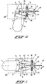
- Fig. 1 depicts a swivel castor of a wheelchair according to the invention.
- the swivel castor substantially comprises a castor 1 which by means of a horizontal castor axle 2 is fastened in a substantially U-shaped frame 4.
- a vertical swivel axle 5 is arranged on top of the frame 4.
- the straight-on direction of travel of the wheelchair, both forwards and in reverse, is indicated by line 3.
- the swivel axle 5 is fastened in the chassis 40, which is indicated diagrammatically by the dashed line, of the wheelchair according to the invention such that the frame 4 with the castor 1 fastened therein can pivot freely about the vertical swivel axle 5 over a swivel range which lies in a first swivel area.
- Fig. 1 shows means for limiting the swivel range of the swivel castor to a second swivel area which is smaller than the first swivel area.
- the means which limit the swivel range comprise two projections 6, 7, which are arranged at the upper free end of the swivel axle 5.
- the two projections 6, 7 are located diametrically opposite one another on the upper free end of the swivel axle 5 and are thus eccentric with respect to the axis of the swivel axle 5.
- the means which are depicted in Fig. 1 and which limit the swivel range furthermore comprise two arms 9, 10, two pressure-exerting rollers 15, 16 and a Bowden cable 17.
- the arms 9, 10 are fastened pivotably to the chassis 40 of the wheelchair by means of vertical pins 11, 12 and are located symmetrically with respect to a plane through the axis of the swivel axle 5, the arms 9, 10 extending from the pins 11, 12 at least as far as past the swivel axle 5.
- the projections 6, 7 on the upper free end of the swivel axle 5 are situated between the arms 9, 10.
- the arms 9, 10 each have a stop surface 13, 14 against which the projections 6, 7 come to bear.
- the shape of the arms 9, 10 is such that they become wider, in a direction perpendicular to the swivel axle 5, from the pins 11, 12 towards the swivel axle.
- the pressure-exerting rollers 15, 16 have pivot pins 18, 19. Both ends of the pivot pins 18, 19 project into slot-shaped openings in roller holders 20, 21.
- the pivot pins 18, 19 of the pressure-exerting rollers 15, 16 are connected to one another by means of tension springs 22, 23, which are situated in the roller holders 20, 21.
- the tension springs 22, 23 exert forces directed towards one another on the pressure-exerting rollers 15, 16.
- the roller holders 20, 21 are fixedly connected to one another.
- the assembly comprising pressure-exerting rollers 15, 16, roller holders 20, 21 and tension springs 22, 23 can be placed over the arms 9, 10 such that the pressure-exerting rollers 15, 16 act on the outer surfaces of the arms 9, 10.
- the pressure-exerting rollers 15, 16 With the aid of the Bowden cable 17 and an actuating member (not shown), the pressure-exerting rollers 15, 16 are displaced over the outer surfaces of the arms 9, 10.
- the inner cable 24 of the Bowden cable 17 is in this case fixedly connected to the chassis 40.
- the outer cable 25 slides over the inner cable 24 and in the process displaces the pressure-exerting rollers 15, 16.
- the swivel castor can pivot freely about its vertical swivel axle 5 over a swivel range, preferably 360°, which lies in a first swivel area.
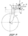
- Fig. 2 depicts the situation in which the pressure-exerting rollers 15, 16 have been displaced by the Bowden cable 17 over the arms 9, 10, from the pivot pins 11, 12 in the direction of the swivel axle 5. Since the arms 9, 10 become wider towards the swivel axle 5, the arms 9, 10 are moved towards one another by the pressure-exerting rollers 15, 16. If the swivel castor seeks to pivot out of the straight-on position of travel, the projections 6, 7 are detained by the arms 9, 10. The restoring forces of the tension springs 22, 23 move the swivel castor into a position which corresponds to the straight-on direction of travel. However, these forces are not so great that the swivel castor can no longer pivot at all.
- the swivel range of the swivel castor is now limited to a second swivel area, and is preferably 15° on either side of the straight-on direction of travel of the swivel castor. Due to the swivelling of the swivel castor, the projections 6, 7 exert a force on the arms 9, 10, as a result of which the latter move apart. The arms 9, 10 in turn exert a force on the pressure-exerting rollers 15, 16 counter to the restoring force of the tension springs 22, 23. As a consequence of this force, the pressure-exerting rollers move apart. The maximum distance between the pressure-exerting rollers 15, 16 is determined by the slot openings in the roller holders 20, 21.
- the second swivel area is thus determined by the slot openings in the roller holders 20, 21.
- a force is exerted on the swivel castor, which force moves the swivel castor into a position which corresponds to the straight-on direction of travel of the wheelchair.
- the force which is exerted on the swivel castor in order to move the swivel castor into the position which corresponds to the straight-on direction of travel of the wheelchair is greater than if the means which limit the swivel range are switched off.
- Fig. 3 illustrates the assembly comprising arms 9, 10, pressure-exerting rollers 15, 16, roller holders 20, 21 and tension springs 22, 23.
- the inner cable 24 of the Bowden cable 17 is fixedly connected to the chassis 40 via support 26.
- the pivot pins 18, 19 are also fixedly connected to the chassis 40.
- the means which limit the swivel range are automatically switched on.
- a control unit in which a number of predetermined speeds can be stored, is provided for this purpose.
- the means which limit the swivel range can be switched on manually.
- the wheelchair according to the invention is preferably a front-wheel drive wheelchair.
- the wheelchair is provided with means for travelling straight on, which means exert on the swivel castor a force which moves the swivel castor into the position which corresponds to the straight-on direction of travel of the wheelchair.
- the means for travelling straight on can be controlled automatically or manually, possible parameters which can be used for the continuous adjustment of the force being the speed of the wheelchair and/or the condition of the ground.
Landscapes
- Engineering & Computer Science (AREA)
- Mechanical Engineering (AREA)
- Health & Medical Sciences (AREA)
- Life Sciences & Earth Sciences (AREA)
- Animal Behavior & Ethology (AREA)
- General Health & Medical Sciences (AREA)
- Public Health (AREA)
- Veterinary Medicine (AREA)
- Handcart (AREA)
- Vehicle Body Suspensions (AREA)
Applications Claiming Priority (2)
| Application Number | Priority Date | Filing Date | Title |
|---|---|---|---|
| NL1003396A NL1003396C1 (nl) | 1996-06-21 | 1996-06-21 | Rolstoel die voorzien is van een zwenkwiel. |
| NL1003396 | 1996-06-21 |
Publications (2)
| Publication Number | Publication Date |
|---|---|
| EP0813852A2 true EP0813852A2 (de) | 1997-12-29 |
| EP0813852A3 EP0813852A3 (de) | 2000-06-14 |
Family
ID=19763054
Family Applications (1)
| Application Number | Title | Priority Date | Filing Date |
|---|---|---|---|
| EP97201834A Withdrawn EP0813852A3 (de) | 1996-06-21 | 1997-06-16 | Rollstuhl mit einer schwenkbaren Laufrolle |
Country Status (3)
| Country | Link |
|---|---|
| US (1) | US5984333A (de) |
| EP (1) | EP0813852A3 (de) |
| NL (1) | NL1003396C1 (de) |
Families Citing this family (23)
| Publication number | Priority date | Publication date | Assignee | Title |
|---|---|---|---|---|
| US6540250B1 (en) * | 2000-05-12 | 2003-04-01 | Clifford D. Peterson | Height adjustable wheelchair |
| CA2464783A1 (en) | 2001-10-26 | 2003-05-01 | Daniel Johnson | Hospital bed power-assist |
| US7533742B2 (en) * | 2001-10-26 | 2009-05-19 | Dane Industries, Inc. | Bed transfer system |
| DE10239717C1 (de) * | 2002-08-29 | 2003-08-14 | Bock Healthcare Gmbh | Rollstuhl mit gelenkten Rädern |
| AU2004236214A1 (en) * | 2003-05-03 | 2004-11-18 | Dane Industries | Cart mover |
| US7389836B2 (en) * | 2003-09-23 | 2008-06-24 | Dane Industries, Inc. | Power-assisted cart retriever with attenuated power output |
| US7571914B2 (en) * | 2003-10-15 | 2009-08-11 | Dane Industries, Inc. | Push-pull cart collection device and conversion assembly |
| CA2542737A1 (en) * | 2003-10-15 | 2005-04-28 | Dane Industries | Cart coupler assembly for cart collection machines |
| US8292327B2 (en) * | 2004-09-15 | 2012-10-23 | Fernando Esteban Araya Moreno | Device for the optional guiding of at least one self-steering wheel of a trolley |
| US20060243500A1 (en) * | 2005-02-25 | 2006-11-02 | Wiff James W | Wheelchair transporter |
| US20070289787A1 (en) * | 2005-02-25 | 2007-12-20 | Dane Industries, Inc. | Wheelchair transporter |
| US7857342B2 (en) | 2005-06-07 | 2010-12-28 | Dane Technologies, Inc. | Hitch assembly |
| US20070013157A1 (en) * | 2005-07-18 | 2007-01-18 | Wiff James W | Dual hitch assembly |
| US20070051541A1 (en) * | 2005-09-07 | 2007-03-08 | Delphi Technologies, Inc. | Method of castor management |
| WO2009103121A1 (en) * | 2008-02-21 | 2009-08-27 | Noah No.1 Pty Ltd | A castor wheel |
| CA2674932A1 (en) | 2008-04-11 | 2009-10-11 | Dane Technologies, Inc. | Cart transporting apparatus |
| US8113305B1 (en) * | 2008-05-22 | 2012-02-14 | Flowers Ip Llc | Powered patient transport vehicle |
| US8684373B2 (en) | 2008-09-23 | 2014-04-01 | Dane Technologies, Inc. | Cart moving machine |
| US9010771B2 (en) | 2009-11-10 | 2015-04-21 | Dane Technologies, Inc. | Utility machine with dual-mode steering |
| US10278694B2 (en) | 2012-02-23 | 2019-05-07 | Northwestern University | Indirect attachment of a needle to a mesh suture |
| WO2013126130A1 (en) | 2012-02-23 | 2013-08-29 | Northwestern University | Improved suture |
| KR101424398B1 (ko) * | 2013-06-21 | 2014-07-28 | 한채진 | 운반대차용 고정 및 회전 겸용 캐스터 |
| US11419773B2 (en) | 2019-11-09 | 2022-08-23 | The Onward Project, LLC | Convertible wheelchair |
Family Cites Families (9)
| Publication number | Priority date | Publication date | Assignee | Title |
|---|---|---|---|---|
| US3802524A (en) * | 1972-06-05 | 1974-04-09 | W Seidel | Motorized invalid carrier |
| US4241932A (en) * | 1979-09-18 | 1980-12-30 | Gerald W. Rothschild | Wheelchair steering apparatus |
| DE8709996U1 (de) * | 1987-07-22 | 1988-11-17 | Meyra Wilhelm Meyer GmbH & Co KG, 4973 Vlotho | Rollstuhl |
| DE3832125A1 (de) * | 1988-01-12 | 1989-07-20 | Ortopedia Gmbh | Elektrorollstuhl |
| GB2269095A (en) * | 1992-07-30 | 1994-02-02 | Intuitive Products Internation | Hand-propelled trolly |
| ATE193056T1 (de) * | 1993-07-16 | 2000-06-15 | Procter & Gamble | Waschmittelzusammensetzungen für geschirrspülmaschinen |
| GB9319701D0 (en) * | 1993-09-24 | 1993-11-10 | Multicontrol Ltd | Castors |
| NL9402006A (nl) * | 1994-11-29 | 1996-07-01 | Seenus Nl Bv R Van | Rolstoelframe, alsmede zwenkwielsamenstel. |
| US5899469A (en) * | 1997-02-06 | 1999-05-04 | Pinto; David Alexander | Vehicle with lockable casters |
-
1996
- 1996-06-21 NL NL1003396A patent/NL1003396C1/nl not_active IP Right Cessation
-
1997
- 1997-06-16 EP EP97201834A patent/EP0813852A3/de not_active Withdrawn
- 1997-06-19 US US08/878,727 patent/US5984333A/en not_active Expired - Fee Related
Also Published As
| Publication number | Publication date |
|---|---|
| NL1003396C1 (nl) | 1997-12-23 |
| US5984333A (en) | 1999-11-16 |
| EP0813852A3 (de) | 2000-06-14 |
Similar Documents
| Publication | Publication Date | Title |
|---|---|---|
| EP0813852A2 (de) | Rollstuhl mit einer schwenkbaren Laufrolle | |
| US4666420A (en) | Toy car of a front wheel driving type | |
| AU773976B2 (en) | Anti-tip caster suspension for a wheelchair | |
| US5437467A (en) | Stabilization device for vehicle | |
| US4128137A (en) | Peripatetic vehicles | |
| JPH1128924A (ja) | キャンバをアクティブに変化させるサスペンションを備えた車両 | |
| DE3662997D1 (en) | Swiwel and spring mounted caster wheel | |
| CA2007219A1 (en) | Trailer suspension apparatus | |
| PL194310B1 (pl) | Pojazd odchylny | |
| EP0529188A1 (de) | Kraftfahrzeug | |
| US5331900A (en) | Overhead trolley with spring biased load dependent traction control | |
| CA2048636A1 (en) | Improved large truck | |
| CA2284382A1 (en) | Reversible caster steerable suspension system | |
| EP0783986A3 (de) | Rollregelungssystem eines Fahrzeuges | |
| JP2004196284A (ja) | 車両サスペンション装置 | |
| US5139279A (en) | Parallel-aligned all-wheel steered vehicle | |
| EP0485273B1 (de) | Fester Scherenstromabnehmer im Verhältnis zu einem Drehgestellrahmen | |
| EP0788439A4 (de) | Bewegliches gestell | |
| US4045050A (en) | Articulated vehicle tilt limiting apparatus | |
| EP0557892A3 (en) | A motorized bogie for a rail vehicle | |
| JPH081553A (ja) | ロボット搭載型無人搬送車 | |
| EP1078622B1 (de) | Untergestell für Fahrzeug und Rollstuhl ausgestattet mit solchen Untergestell | |
| JP2023154808A (ja) | 自動搬送車 | |
| JPH08188027A (ja) | 輪距調整装置 | |
| JPH09169271A (ja) | 電動式搬送車 |
Legal Events
| Date | Code | Title | Description |
|---|---|---|---|
| PUAI | Public reference made under article 153(3) epc to a published international application that has entered the european phase |
Free format text: ORIGINAL CODE: 0009012 |
|
| AK | Designated contracting states |
Kind code of ref document: A2 Designated state(s): DE DK FR GB NL SE |
|
| PUAL | Search report despatched |
Free format text: ORIGINAL CODE: 0009013 |
|
| AK | Designated contracting states |
Kind code of ref document: A3 Designated state(s): AT BE CH DE DK ES FI FR GB GR IE IT LI LU MC NL PT SE |
|
| RIC1 | Information provided on ipc code assigned before grant |
Free format text: 7A 61G 5/04 A, 7A 61G 5/10 B |
|
| AKX | Designation fees paid |
Free format text: DE DK FR GB NL SE |
|
| STAA | Information on the status of an ep patent application or granted ep patent |
Free format text: STATUS: THE APPLICATION IS DEEMED TO BE WITHDRAWN |
|
| 18D | Application deemed to be withdrawn |
Effective date: 20001215 |