EP0812607A2 - Verfahren zur Nachbehandlung von Rohdestillat - Google Patents
Verfahren zur Nachbehandlung von Rohdestillat Download PDFInfo
- Publication number
- EP0812607A2 EP0812607A2 EP97109670A EP97109670A EP0812607A2 EP 0812607 A2 EP0812607 A2 EP 0812607A2 EP 97109670 A EP97109670 A EP 97109670A EP 97109670 A EP97109670 A EP 97109670A EP 0812607 A2 EP0812607 A2 EP 0812607A2
- Authority
- EP
- European Patent Office
- Prior art keywords
- distillate
- cooling
- temperature
- tub
- jacket
- Prior art date
- Legal status (The legal status is an assumption and is not a legal conclusion. Google has not performed a legal analysis and makes no representation as to the accuracy of the status listed.)
- Granted
Links
Images

Classifications
-
- B—PERFORMING OPERATIONS; TRANSPORTING
- B01—PHYSICAL OR CHEMICAL PROCESSES OR APPARATUS IN GENERAL
- B01D—SEPARATION
- B01D5/00—Condensation of vapours; Recovering volatile solvents by condensation
- B01D5/0078—Condensation of vapours; Recovering volatile solvents by condensation characterised by auxiliary systems or arrangements
- B01D5/009—Collecting, removing and/or treatment of the condensate
-
- B—PERFORMING OPERATIONS; TRANSPORTING
- B01—PHYSICAL OR CHEMICAL PROCESSES OR APPARATUS IN GENERAL
- B01D—SEPARATION
- B01D3/00—Distillation or related exchange processes in which liquids are contacted with gaseous media, e.g. stripping
- B01D3/001—Processes specially adapted for distillation or rectification of fermented solutions
- B01D3/003—Rectification of spirit
- B01D3/004—Rectification of spirit by continuous methods
- B01D3/005—Combined distillation and rectification
-
- B—PERFORMING OPERATIONS; TRANSPORTING
- B01—PHYSICAL OR CHEMICAL PROCESSES OR APPARATUS IN GENERAL
- B01D—SEPARATION
- B01D5/00—Condensation of vapours; Recovering volatile solvents by condensation
- B01D5/0057—Condensation of vapours; Recovering volatile solvents by condensation in combination with other processes
- B01D5/006—Condensation of vapours; Recovering volatile solvents by condensation in combination with other processes with evaporation or distillation
- B01D5/0066—Dome shaped condensation
-
- C—CHEMISTRY; METALLURGY
- C12—BIOCHEMISTRY; BEER; SPIRITS; WINE; VINEGAR; MICROBIOLOGY; ENZYMOLOGY; MUTATION OR GENETIC ENGINEERING
- C12H—PASTEURISATION, STERILISATION, PRESERVATION, PURIFICATION, CLARIFICATION OR AGEING OF ALCOHOLIC BEVERAGES; METHODS FOR ALTERING THE ALCOHOL CONTENT OF FERMENTED SOLUTIONS OR ALCOHOLIC BEVERAGES
- C12H6/00—Methods for increasing the alcohol content of fermented solutions or alcoholic beverages
- C12H6/02—Methods for increasing the alcohol content of fermented solutions or alcoholic beverages by distillation
-
- Y—GENERAL TAGGING OF NEW TECHNOLOGICAL DEVELOPMENTS; GENERAL TAGGING OF CROSS-SECTIONAL TECHNOLOGIES SPANNING OVER SEVERAL SECTIONS OF THE IPC; TECHNICAL SUBJECTS COVERED BY FORMER USPC CROSS-REFERENCE ART COLLECTIONS [XRACs] AND DIGESTS
- Y02—TECHNOLOGIES OR APPLICATIONS FOR MITIGATION OR ADAPTATION AGAINST CLIMATE CHANGE
- Y02A—TECHNOLOGIES FOR ADAPTATION TO CLIMATE CHANGE
- Y02A20/00—Water conservation; Efficient water supply; Efficient water use
Definitions
- the invention relates to a process for the aftertreatment of crude distillate after distillation.
- the distillate is in the form of the so-called raw distillate or raw brandy.
- the composition of the raw brandy can be influenced within wide limits by the choice of the distillation process.
- Such a process for the continuous recovery of purified alcohol, i.e. H. Ethanol from fermented mash is known for example from DE 32 41 493 C2. Specifically, this is a special distillation process in raw, fine and separation columns. The main aim of the process described therein is to separate the leading components before reaching the fine combustion column.
- a distillation device is also known from DE 38 28 320 C2, in which pollutants are to be reduced in a targeted manner during the production of brandy, in particular from stone fruit.
- pollutants are to be reduced in a targeted manner during the production of brandy, in particular from stone fruit.
- it is a matter of obtaining a distillate containing as little urethane or cyanide as possible. This is done by means of a catalytic converter on which the litter is enriched with pollutants, which can be traced back to different places on the aroma or directly to the mash bladder.
- the maximum concentrations of these constituents in the raw spirit suitable for drinking spirits are stipulated by law, for example the aldehyde content may not exceed 4 mg / l, the fusel oil content not more than 5 mg / l, and the acidity not more than 3 mg / l and the methanol content at most 1200 - 1500 g / hl r. A. amount.
- the process according to the invention now begins where the distillate has cooled down in the cooling tub to a temperature which corresponds to approximately room temperature, ie 20 ° C. or slightly above, after the distillation process has ended.
- the temperature is significantly lower than the boiling point of the ethanol, ie the spirit. Otherwise, the ethanol content would decrease continuously, since under the given normal pressure, ie the typical, climate-related air pressure, the alcohol content of the raw brandy would decrease within a short time.
- the temperature of the crude distillate in the cooling tub is set in a range from approximately 15 ° C. to approximately 50 ° C.
- a vapor phase forms in the space above the liquid distillate in the cooling tub, in which the vapor pressure of the individual components is in equilibrium with the liquid.
- the method according to the invention is practically a quasi-static - since under normal conditions - fractional post-distillation, by means of which the quality of the raw distillate is increased again, even in the case of particularly carefully distilled fine spirits.
- a preferred sequence of the method according to the invention provides that the distillate temperature is carried out under normal ambient pressure at 15-25 ° C. This ensures that practically no ethanol is drawn off even after a long aftertreatment.
- the distillate temperature in particular in the aftertreatment of fruit brandies, which are sometimes characterized by an increased cyanide content, it can be advantageous for the distillate temperature to be greater than 20 ° C., at which the maximum upper limit, i.e. H. the boiling temperature of ethanol (78.32 ° C) is not exceeded.
- H. the boiling temperature of ethanol
- An advantageous development of the method according to the invention provides for the further method step that gas is blown into the crude distillate.
- an inert or reactive gas is introduced during the aftertreatment via nozzles or gas distributors installed in the part of the tub filled with raw distillate.
- the resulting gas bubbles significantly increase the liquid surface, so that the efficiency of the The method according to the invention is improved with respect to the removal of the pollutants.
- Carbon dioxide or nitrogen is preferably used as the gas; however, other gases and gas mixtures can also be used.
- a device for carrying out the method according to the invention provides that a closed cooling tub has a temperature control device in its lower part that can be filled with raw distillate, and separately temperature-controlled cooling surfaces are provided in the space above the distillate, which are provided with a condensate extraction device.
- the cooling tub designed according to the invention has two temperature control devices that can be temperature-controlled separately from one another.
- One temperature control device is used to cool the liquid raw distillate.
- cooling surfaces that can be cooled are attached independently of the first temperature control device. In this way, any temperature differences can be set between the distillate and the cooling surfaces arranged in the steam space.
- the cooling surfaces can expediently also be formed by the surfaces of a cooling jacket.
- a particularly advantageous embodiment of the device according to the invention provides that the cooling tub is cylindrical and has a cover which tapers conically upwards, a tempering jacket being arranged in the jacket and bottom of the cylindrical part and a cooling jacket being arranged in the jacket of the conical lid, the conical of which Internal surfaces form the cooling surfaces, and a circumferential collecting channel is provided as a condensate removal device in the interior of the cover, which is connected to a condensate discharge line led to the outside.
- This embodiment results in a compact device which, while having the same shape, can be dimensioned for both smaller and larger filling quantities.
- the arrangement of the cooling surface on the upwardly tapering inner surface of the cover ensures that the condensate drops run downward on the cooling surface, where they are collected in a condensate collecting channel running all around the inside of the cover.
- the condensate collecting channel can be emptied to the outside via the condensate drain line, which can be designed as a small opening or as a drain pipe.
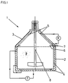
- the device designed as a cooling tub is provided as a whole with the reference numeral 1.
- This has a cylindrical, pot-shaped container 2, which is closed at the top with an upwardly tapering lid 3. This can be removed from the container 2.
- a temperature jacket 4 Arranged in the interior of the lateral surface and in the bottom of the container 2 is a temperature jacket 4 which can be acted upon with a cooling or heating medium and which is connected to a temperature control device T. Inside in the conical outer surface of the cover 3 is a coolant acted upon cooling jacket 5 is arranged, which is connected to a cooling device K, which is designed as a cooling circuit.
- a condensate collecting channel 6 is arranged all around, which is connected to a condensate discharge line 7 which leads to the outside.
- a motorized agitator 8 is arranged in the cover 3, which projects into the container 2.
- the maximum filling level of the container 2 with raw distillate 9 ends approximately just below its upper edge, where the lid 3 is placed.
- FIG. 2 and 3 show a practical embodiment of a cooling tub 1 according to FIG. 1.
- the same reference numerals are used here.
- the angle ⁇ of the cooling jacket 5 in the cover 3 is approximately 40 ° here relative to the horizontal.
- the device 1 is relatively flat, but it is always ensured that condensate drops run on the cooling jacket 5 into the condensate collecting channel 6 without dripping into the container 2.
- an outlet nozzle 10 is arranged at the bottom of the container 2, via which the crude distillate 9 can be drained off after the aftertreatment.
- liquid raw distillate 9 is poured into the container 2 of the cooling tub 1 and the lid 3 is closed.
- the temperature control jacket 4 is set to a preselected temperature, for example 20 ° C.
- the cooling jacket 5 is cooled to a temperature below the temperature of the temperature jacket 4 by means of the cooling device K.
- the liquid raw distillate 9 located in the container 2 is kept in motion by means of the agitator 8.
- a vapor equilibrium is formed, which is dependent on the temperature of the tempering jacket 4, which corresponds to the liquid crude distillate 9, and the ambient pressure, ie. H. the normal pressure.
- the temperature of the crude distillate 9 is chosen so that harmful ingredients preferably pass into the vapor phase, but the boiling point of ethanol at normal pressure (78.32 ° C.) is not exceeded.
- the cooling jacket 5 is cooled to such an extent that the harmful constituents condense to form drops on it, which run off into the condensate collecting channel 6 and can be drawn off to the outside via the condensate discharge line 7. This process is a quasi-static process which takes place approximately under normal conditions and in which practically only the harmful ingredients are removed from the crude distillate 9. This gives you a very high quality end product.
Landscapes
- Chemical & Material Sciences (AREA)
- Chemical Kinetics & Catalysis (AREA)
- Engineering & Computer Science (AREA)
- Organic Chemistry (AREA)
- General Engineering & Computer Science (AREA)
- Food Science & Technology (AREA)
- Biochemistry (AREA)
- Bioinformatics & Cheminformatics (AREA)
- Health & Medical Sciences (AREA)
- General Health & Medical Sciences (AREA)
- Genetics & Genomics (AREA)
- Life Sciences & Earth Sciences (AREA)
- Wood Science & Technology (AREA)
- Zoology (AREA)
- Vaporization, Distillation, Condensation, Sublimation, And Cold Traps (AREA)
- Organic Low-Molecular-Weight Compounds And Preparation Thereof (AREA)
- Alcoholic Beverages (AREA)
- Seasonings (AREA)
Abstract
- Temperierung des Rohdestillats im geschlossenen Kühlbottich bei Normaldruck auf eine Destillat-Temperatur, die deutlich unter der Siedetemperatur von Ethanol bei Normaldruck liegt,
- Kondensation von Destillatbestandteilen im dampfgefüllten oberen Bereich des Kühlbottichs bei Normaldruck an Kühlflächen, die kälter sind als die Destillat-Temperatur,
- Abzug des Kondensats von den Kühlflächen aus dem Kühlbottich.
Description
- Die Erfindung betrifft ein Verfahren zur Nachbehandlung von Rohdestillat nach der Destillation.
- Nach dem eigentlichen Destillationsvorgang liegt das Destillat in Form des sogenannten Rohdestillats bzw. Rohbrands vor. Durch die Wahl des Destillationsverfahrens läßt sich die Zusammensetzung des Rohbrandes in weiten Grenzen beeinflussen.
- Ein derartiges Verfahren zur kontinuierlichen Gewinnung von gereinigtem Alkohol, d. h. Ethanol, aus vergorener Maische ist beispielsweise aus der DE 32 41 493 C2 bekannt. Im einzelnen handelt es sich dabei um einen speziellen Destillationsprozeß in Rohbrenn-, Feinbrenn- und Trennkolonnen. Das darin beschriebene Verfahren hat im wesentlichen zum Ziel, die Vorlaufbestandteile vor Erreichen der Feinbrennkolonne abzutrennen.
- Aus der DE 38 28 320 C2 ist weiterhin eine Destillationsvorrichtung bekannt, bei der gezielt Schadstoffe während der Gewinnung von Branntwein, insbesondere aus Steinobst, verringert werden sollen. Im einzelnen geht es dabei darum, ein möglichst keinerlei Urethan oder Zyanide enthaltendes Destillat zu gewinnen. Dies geschieht mittels eines Katalysators, an dem mit Schadstoffen angereicherter Lutter anfällt, der zu unterschiedlichen Stellen des Aromators oder direkt zur Maischeblase rückführbar ist.
- Die vorbekannten Verfahren und Vorrichtungen verfolgen allesamt den Ansatz, das Destillat, d. h. den Rohbrand, auf möglichst geringe Schadstoffanteile zu optimieren. Neben den Hauptprodukten Ethanol und Kohlendioxyd liefert die Gärung nämlich je nach Ausgangsprodukten ca. 4 - 5 % unterschiedliche Nebenprodukte, wobei neben einer Vielzahl anderer Bestandteile insbesondere Methanol und höhere Alkohole, insbesondere die hauptsächlich aus Pentanolen, Isobutanol, etc. bestehenden sogenannten Fuselöle zu nennen sind.
- Angesichts der zum Teil gesundheitsschädigenden Wirkung der Gärungs-Nebenprodukte sind die Maximalkonzentrationen dieser Bestandteile im für Trinkbranntweinzwecke geeigneten Rohsprit gesetzlich festgelegt, beispielsweise darf der Aldehyd-Gehalt höchstens 4 mg/l, der Fuselöl-Gehalt höchstens 5 mg/l, der Säuregrad höchstens 3 mg/l und der Methanol-Gehalt höchstens 1200 - 1500 g/hl r. A. betragen.
- Es hat sich nun gezeigt, daß die Einhaltung der gesetzlichen Vorschriften zu einem Rohdestillat führt, welches nach Verdünnung auf Trinkstärke zwar in der Regel einen Branntwein ergibt, welcher ohne unmittelbare gesundheitliche Schäden durch die in ihm enthaltenden Nebenprodukte der Gärung konsumiert werden kann. Man hat allerdings gleichfalls festgestellt, daß selbst ein besonders sorgfältig hergestelltes Rohdestillat, dessen schädliche Inhaltsstoffe weit unterhalb der gesetzlich erlaubten Grenzwerte liegen, höchsten geschmacklichen Qualitätsansprüchen, wie sie an sogenannte Edelbrände gestellt werden, manchmal nicht gerecht werden. Dies liegt zum Teil daran, daß der Gärungsvorgang ein höchst komplexer chemischer Prozeß ist, wobei sich die Zusammensetzung des Ausgangsprodukts nicht zuletzt angesichts der natürlichen Abweichungen der Ausgangsprodukte - wie Früchte und dergleichen - nicht bis in alle Einzelheiten beherrschen läßt.
- Die Folge sind nicht beherrschbare Qualitätsschwankungen, die von einer Trübung des Genußerlebnisses bis hin zu körperlichen Beschwerden bei empfindlichen Personen führen können.
- Daraus ergibt sich die Aufgabe der Erfindung, ein Verfahren zur Nachbehandlung von Rohdestillat nach der Destillation zur Verfügung zu stellen, welches die geschmackliche Qualität und die Verträglichkeit des Endproduktes durch eine Verminderung der Schadstoffe verbessert.
- Zur Lösung dieser Aufgabe schlägt die Erfindung ein Verfahren mit folgenden Verfahrensschritten vor:
- Temperierung des Rohdestillats im geschlossenen Kühlbottich bei Normaldruck auf eine Destillat-Temperatur, die deutlich unterhalb der Siedetemperatur von Ethanol bei Normaldruck liegt,
- Kondensation von Destillatbestandteilen im dampfgefüllten oberen Bereich des Kühlbottichs bei Normaldruck an Kühlflächen, die kälter sind als die Destillat-Temperatur,
- Abzug des Kondensats von den Kühlflächen aus dem Kühlbottich.
- Nach dem Stand der Technik ist es üblich, das Rohdestillat nach der Destillation in einen Kühlbottich einzufüllen und vor der Filtration auf eine niedrigere Temperatur zu bringen, so daß z. B. Fuselöle bei der nachfolgenden Filtration aus dem Rohdestillat entfernt werden. Das erfindungsgemäße Verfahren setzt nun dort an, wo das Destillat nach dem Abschluß des Destillationsvorgangs im Kühlbottich auf eine Temperatur heruntergekühlt ist, die in etwa Raumtemperatur, d. h. 20 °C, oder etwas darüber entspricht. Jedenfalls ist die Temperatur dabei deutlich niedriger als die Siedetemperatur des Ethanols, d. h. des Weingeistes. Andernfalls würde der Ethanol-Gehalt kontinuierlich sinken, da unter dem gegebenen Normaldruck, d. h. dem typischen, klimabedingten Luftdruck, sich der Alkoholgehalt des Rohbrandes innerhalb kurzer Zeit verringern würde. Nach dem erfindungsgemäßen Verfahren wird die Temperatur des Rohdestillats in dem Kühlbottich in einem Bereich von etwa 15 °C bis etwa 50 °C eingestellt. Dabei bildet sich in dem Raum oberhalb des flüssigen Destillates in dem Kühlbottich eine Dampfphase, in der der Dampfdruck der einzelnen Bestandteile mit der Flüssigkeit im Gleichgewicht steht.
- Man hat nun festgestellt, daß die den Geschmack beeinträchtigenden Schadstoffe bei den erfindungsgemäßen Temperatur- und Druckbedingungen offenbar einen höheren Dampfdruck haben als Ethanol. Diesen Umstand macht sich das erfindungsgemäße Verfahren dadurch zunutze, daß innerhalb der Dampfphase Kühlflächen angeordnet sind, die kälter sind als die Destillat-Temperatur. An diesen Kühlflächen kondensieren bevorzugt diese geschmacks-beeinträchtigenden Schadstoffe und können einfach aus dem Kühlbottich abgezogen werden.
- Bei dem erfindungsgemäßen Verfahren handelt es sich praktisch um eine quasi-statische - da unter Normalbedingungen - fraktionierte Nachdestillation, durch welche die Qualität des Rohdestillates, selbst bei besonders sorgfältig gebrannten Edelbränden, nochmals gesteigert wird.
- Ein bevorzugter Ablauf des erfindungsgemäßen Verfahrens sieht vor, daß die Destillat-Temperatur unter normalem Umgebungsdruck bei 15 - 25 °C erfolgt. Dadurch ist sichergestellt, daß auch bei einer längeren Nachbehandlung praktisch kein Ethanol mit abgezogen wird.
- Insbesondere bei der Nachbehandlung von Obstbränden, die sich mitunter durch einen erhöhten Zyanid-Gehalt auszeichnen, kann es von Vorteil sein, daß die Destillat-Temperatur größer ist als 20 °C, bei der die maximale Obergrenze, d. h. die Siedetemperatur von Ethanol (78,32 °C) nicht überschritten wird. Dadurch ist es möglich, Zyanid-Verbindungen, die bei etwa 34 °C in die Dampfphase übergehen, mittels des erfindungsgemäßen Verfahrens aus dem Rohbrand zu entfernen. Es ist offensichtlich, daß dadurch nicht nur die Bekömmlichkeit des Branntweins erhöht wird, sondern auch die gesundheitsschädlichen Nebenwirkungen minimiert werden.
- Eine vorteilhafte Weiterbildung des erfindungsgemäßen Verfahrens sieht den weiteren Verfahrensschritt vor, daß Gas in das Rohdestillat eingeblasen wird. Hierzu wird während der Nachbehandlung über in dem mit Rohdestillat gefüllten Teil des Bottichs installierte Düsen bzw. Gasverteiler ein Inert- oder Reaktivgas eingeleitet. Durch die dabei entstehenden Gasblasen wird die Flüssigkeitsoberfläche deutlich vergrößert, so daß die Effizienz des erfindungsgemäßen Verfahrens in Bezug auf die Entfernung der Schadstoffe verbessert wird. Als Gas gelangt bevorzugt Kohlendioxyd oder Stickstoff zum Einsatz; es können jedoch auch andere Gase und Gasgemische verwendet werden.
- Eine Vorrichtung zur Durchführung des erfindungsgemäßen Verfahrens sieht vor, daß ein geschlossener Kühlbottich in seinem unteren, mit Rohdestillat befüllbaren Teil eine Temperiervorrichtung aufweist und in dem Raum oberhalb des Destillats separat temperierbare Kühlflächen angebracht sind, die mit einer Kondensat-Abzugsvorrichtung versehen sind.
- Der erfindungsgemäß ausgestaltete Kühlbottich weist zwei separat voneinander temperierbare Temperiervorrichtungen auf. Die eine Temperiervorrichtung dient zur Kühlung des flüssigen Rohdestillats. Es ist allerdings gleichfalls denkbar, bei kalten Umgebungstemperaturen das Destillat auf die gewünschte Temperatur zu erwärmen. In dem Raum oberhalb des Flüssigkeitsspiegels des Destillats, d. h. unterhalb des Deckels des Kühlbottichs, sind unabhängig von der ersten Temperiervorrichtung kühlbare Kühlflächen angebracht. Auf diese Weise lassen sich zwischen dem Destillat und dem im Dampfraum angeordneten Kühlflächen beliebige Temperaturdifferenzen einstellen. Die Kühlflächen können zweckmäßigerweise ebenfalls durch die Oberflächen eines Kühlmantels gebildet werden.
- Eine besonders vorteilhafte Ausführungsform der erfindungsgemäßen Vorrichtung sieht vor, daß der Kühlbottich zylindrisch ausgebildet ist und einen nach oben konisch zulaufenden Deckel aufweist, wobei ein Temperiermantel im Mantel und Boden des zylindrischen Teils angeordnet ist und ein Kühlmantel im Mantel des konischen Deckels angeordnet ist, dessen konische Innenflächen die Kühlflächen bilden, und als Kondensat-Abzugsvorrichtung im Innern des Deckels eine umlaufende Auffangrinne vorgesehen ist, die mit einer nach außen geführten Kondensat-Abzugsleitung verbunden ist.
- In dieser Ausführungsform ergibt sich ein kompaktes Gerät, welches bei gleichbleibender Form sowohl für kleinere als auch größere Füllmengen dimensioniert werden kann.
- Durch die Anordnung der Kühlfläche auf der nach oben zulaufenden, konischen Innenfläche des Deckels wird gewährleistet, daß die Kondensat-Tropfen auf der Kühlfläche nach unten ablaufen, wo sie in einer im Innern des Deckels ringsum umlaufenden Kondensat-Sammelrinne gesammelt werden. Die Kondensat-Sammelrinne kann über die Kondensat-Abzugsleitung, die als kleine Öffnung oder als Ablaufrohr ausgebildet sein kann, nach außen hin entleert werden.
- Ausführungsbeispiele der erfindungsgemäßen Vorrichtung sind anhand der Zeichnungen näher erläutert. Es zeigen im einzelnen:
- Fig. 1
- eine schematische Darstellung einer erfindungsgemäßen Vorrichtung;
- Fig. 2
- eine vergrößerte Schnittdarstellung eines Kühlbottichs gemäß Fig. 1;
- Fig. 3
- eine perspektivische Ansicht des Kühlbottichs gemäß Fig. 2 mit aufgeklapptem Deckel.
- In Fig. 1 ist die als Kühlbottich ausgebildete erfindungsgemäße Vorrichtung als Ganzes mit dem Bezugszeichen 1 versehen. Dieser weist einen zylindrischen, topfförmigen Behälter 2 auf, der oben mit einem nach oben konisch zulaufenden Deckel 3 verschlossen ist. Dieser ist von dem Behälter 2 abnehmbar.
- Im Inneren der Mantelfläche sowie im Boden des Behälters 2 ist ein mit einem Kühl- bzw. Heizmedium beaufschlagbarer Temperiermantel 4 angeordnet, der an eine Temperiervorrichtung T angeschlossen ist. Innen in der konischen Mantelfläche des Deckels 3 ist ein mit Kühlmittel beaufschlagbarer Kühlmantel 5 angeordnet, der an einen Kühlvorrichtung K angeschlossen ist, die als Kühlkreislauf ausgebildet ist.
- Am unteren Rand des Kühlmantels 5 ist umlaufend eine Kondensat-Auffangrinne 6 angeordnet, die mit einer nach außen geführten Kondensat-Abzugsleitung 7 verbunden ist.
- Weiterhin ist in dem Deckel 3 ein motorisiertes Rührwerk 8 angeordnet, welches in den Behälter 2 hineinragt.
- Die maximale Füllhöhe des Behälters 2 mit Rohdestillat 9 endet etwa knapp unterhalb seiner Oberkante, wo der Deckel 3 aufgesetzt wird.
- In Fig. 2 und Fig. 3 ist eine praktische Ausführungsform eines Kühlbottichs 1 gemäß Fig. 1 dargestellt. Dabei finden die gleichen Bezugszeichen Verwendung.
- Im einzelnen ist deutlich erkennbar, daß der Winkel α des Kühlmantels 5 in dem Deckel 3 hier etwa 40° gegen die Waagerechte beträgt. Dadurch baut die Vorrichtung 1 relativ flach, es ist jedoch immer gewährleistet, daß Kondensat-Tropfen auf dem Kühlmantel 5 in die Kondensat-Auffangrinne 6 ablaufen, ohne in den Behälter 2 zu tropfen. Weiterhin ist an dem Behälter 2 unten ein Ablaufstutzen 10 angeordnet, über den das Rohdestillat 9 nach der Nachbehandlung abgelassen werden kann.
- Zur Durchführung des erfindungsgemäßen Verfahrens mit der Vorrichtung gemäß Fig. 1 - 3 wird flüssiges Rohdestillat 9 in den Behälter 2 des Kühlbottichs 1 eingefüllt und der Deckel 3 geschlossen. Mittels der Temperiervorrichtung T wird der Temperiermantel 4 auf eine vorgewählte Temperatur, beispielsweise 20 °C, eingestellt. Mittels der Kühlvorrichtung K wird der Kühlmantel 5 auf eine Temperatur unterhalb der Temperatur des Temperiermantels 4 abgekühlt. Während des gesamten Vorganges wird mittels des Rührwerkes 8, das in dem Behälter 2 befindliche flüssige Rohdestillat 9 in Bewegung gehalten.
- In dem nicht mit Destillat gefüllten Raum innerhalb des Deckels 3 bildet sich ein Dampfgleichgewicht aus, welches von der Temperatur des Temperiermantels 4, die mit dem flüssigen Rohdestillat 9 übereinstimmt und dem Umgebungsdruck, d. h. dem Normaldruck, bestimmt wird. Die Temperatur des Rohdestillates 9 wird so gewählt, daß bevorzugt schädliche Inhaltsstoffe in die Dampfphase übergehen, die Siedetemperatur von Ethanol bei Normaldruck (78,32 °C) jedoch nicht überschritten wird. Der Kühlmantel 5 wird soweit abgekühlt, daß an ihm die schädlichen Inhaltsstoffe zu Tropfen kondensieren, die in die Kondensat-Auffangrinne 6 ablaufen und über die Kondensat-Abzugsleitung 7 nach außen abgezogen werden können. Bei diesem Vorgang handelt es sich um einen quasi statischen Prozeß, der annähernd unter Normalbedingungen stattfindet und bei dem praktisch ausschließlich die schädlichen Inhaltsstoffe aus dem Rohdestillat 9 entfernt werden. Dadurch erhält man einen qualitativ äußerst hochwertiges Endprodukt.
Claims (10)
- Verfahren zur Nachbehandlung von Rohdestillat nach der Destillation, gekennzeichnet durch die Verfahrensschritte• Temperierung des Destillats im geschlossenen Kühlbottich bei Normaldruck auf eine Destillat-Temperatur, die unterhalb der Siedetemperatur von Ethanol bei Normaldruck liegt,• Kondensation von Destillatbestandteilen im dampfgefüllten oberen Bereich des Kühlbottichs bei Normaldruck an Kühlflächen, die kälter sind als die Destillat-Temperatur,• Abzug des Kondensats von den Kühlflächen aus dem Kühlbottich.
- Verfahren nach Anspruch 1, dadurch gekennzeichnet, daß die Destillat-Temperatur bei Raumtemperatur liegt.
- Verfahren nach Anspruch 1, dadurch gekennzeichnet, daß die Destillat-Temperatur oberhalb von 20 °C und unterhalb der Siedetemperatur von Ethanol (78,32 °C) liegt.
- Verfahren nach Anspruch 1, dadurch gekennzeichnet, daß Gas in das Rohdestillat eingeblasen wird.
- Verfahren nach Anspruch 4, dadurch gekennzeichnet, daß das Gas Kohlendioxyd ist.
- Vorrichtung zur Durchführung des Verfahrens nach Anspruch 1, dadurch gekennzeichnet, daß ein geschlossener Kühlbottich (1) in seinem unteren, mit Rohdestillat (9) befüllbaren Teil (2) eine Temperiervorrichtung (T, 4) aufweist und in dem Raum oberhalb des Destillats (9) separat temperierbare Kühlflächen (K, 5) angebracht sind, die mit einer Kondensat-Abzugsvorrichtung (6, 7) versehen sind.
- Vorrichtung nach Anspruch 6, dadurch gekennzeichnet, daß die Temperiervorrichtung (T, 4) einen Kühlmantel (4) aufweist.
- Vorrichtung nach Anspruch 6, dadurch gekennzeichnet, daß die Kühlflächen einen Kühlmantel (5) aufweisen.
- Vorrichtung nach Anspruch 6, dadurch gekennzeichnet, daß der Kühlbottich (2) zylindrisch ausgebildet ist und einen nach oben konisch zulaufenden Deckel (3) aufweist, wobei ein Temperiermantel (4) im Mantel und Boden des zylindrischen Teils (2) angeordnet ist und ein zweiter Kühlmantel (5) im Mantel des konischen Deckels (3) angeordnet ist, dessen konische Innenflächen die Kühlflächen bilden, und wobei als Kondensat-Abzugsvorrichtung (6, 7) eine im Innern des Deckels (3) umlaufende Auffangrinne (6) vorgesehen ist, die mit einer nach außen geführten Kondensat-Abzugsleitung (7) verbunden ist.
- Vorrichtung nach Anspruch 6, dadurch gekennzeichnet, daß der Kühlbottich (1) eine Gas-Einblasvorrichtung aufweist.
Applications Claiming Priority (2)
| Application Number | Priority Date | Filing Date | Title |
|---|---|---|---|
| DE19623864A DE19623864C1 (de) | 1996-06-14 | 1996-06-14 | Verfahren zur Nachbehandlung von Rohdestillat |
| DE19623864 | 1996-06-14 |
Publications (3)
| Publication Number | Publication Date |
|---|---|
| EP0812607A2 true EP0812607A2 (de) | 1997-12-17 |
| EP0812607A3 EP0812607A3 (de) | 1998-01-07 |
| EP0812607B1 EP0812607B1 (de) | 2002-09-11 |
Family
ID=7797000
Family Applications (1)
| Application Number | Title | Priority Date | Filing Date |
|---|---|---|---|
| EP97109670A Expired - Lifetime EP0812607B1 (de) | 1996-06-14 | 1997-06-13 | Verfahren zur Nachbehandlung von Rohdestillat |
Country Status (3)
| Country | Link |
|---|---|
| EP (1) | EP0812607B1 (de) |
| AT (1) | ATE223747T1 (de) |
| DE (2) | DE19623864C1 (de) |
Cited By (1)
| Publication number | Priority date | Publication date | Assignee | Title |
|---|---|---|---|---|
| FR2790481A1 (fr) * | 1999-03-05 | 2000-09-08 | Inst Francais Du Petrole | Procede de reduction de la teneur en methanol d'une eau-de-vie |
Family Cites Families (8)
| Publication number | Priority date | Publication date | Assignee | Title |
|---|---|---|---|---|
| DE157066C (de) * | 1903-02-06 | |||
| GB1251800A (de) * | 1967-11-23 | 1971-10-27 | ||
| DE2431885A1 (de) * | 1974-07-03 | 1976-01-15 | Klaus Ing Grad Wall | Vorrichtung zum erzeugen von alkohol |
| US4073955A (en) * | 1976-10-07 | 1978-02-14 | Koppelman & Goodman Enterprises | Apparatus and method for aging liquor |
| DE3241493C2 (de) * | 1982-11-10 | 1984-08-30 | Gebr. Kisker oHG, 4802 Halle | Verfahren zur kontinuierlichen Gewinnung von gereinigtem Alkohol aus vergorener Maische |
| DE3828320C2 (de) * | 1988-08-20 | 1994-02-24 | Ulrich Kothe | Destillationsvorrichtung zur Verringerung bzw. Beseitigung von Schadstoffen während der Gewinnung von Branntwein insbesondere aus Steinobst |
| DE9003692U1 (de) * | 1990-03-30 | 1990-06-28 | Degussa Ag, 6000 Frankfurt | Vorrichtung zum Auffangen von verdampfenden Flüssigkeiten |
| DE9406255U1 (de) * | 1994-04-15 | 1994-06-30 | Breuer, Ingeborg, 09113 Chemnitz | Anordnung zur Gewinnung kleiner Mengen reinen Wassers |
-
1996
- 1996-06-14 DE DE19623864A patent/DE19623864C1/de not_active Expired - Fee Related
-
1997
- 1997-06-13 EP EP97109670A patent/EP0812607B1/de not_active Expired - Lifetime
- 1997-06-13 AT AT97109670T patent/ATE223747T1/de not_active IP Right Cessation
- 1997-06-13 DE DE59708168T patent/DE59708168D1/de not_active Expired - Fee Related
Cited By (1)
| Publication number | Priority date | Publication date | Assignee | Title |
|---|---|---|---|---|
| FR2790481A1 (fr) * | 1999-03-05 | 2000-09-08 | Inst Francais Du Petrole | Procede de reduction de la teneur en methanol d'une eau-de-vie |
Also Published As
| Publication number | Publication date |
|---|---|
| EP0812607A3 (de) | 1998-01-07 |
| ATE223747T1 (de) | 2002-09-15 |
| EP0812607B1 (de) | 2002-09-11 |
| DE19623864C1 (de) | 1997-12-04 |
| DE59708168D1 (de) | 2002-10-17 |
Similar Documents
| Publication | Publication Date | Title |
|---|---|---|
| EP0228572B1 (de) | Verfahren zum Herstellen von alkoholreduzierten bzw. alkoholfreien durch natürliche Vergärung erzeugten Getränken | |
| DE69203146T2 (de) | Überkritisches Extraktions- und Fraktionierungsverfahren für Gewürze. | |
| DE2706831A1 (de) | Verfahren zur kontinuierlichen vergaerung von vergaerbaren loesungen mit hefe | |
| DE69621456T2 (de) | Gerät zur entfernung unerwünschter, flüchtiger stoffe aus der bierwürze | |
| DE2519676A1 (de) | Verfahren zur herstellung eines hopfenoelpraeparates | |
| EP0812607B1 (de) | Verfahren zur Nachbehandlung von Rohdestillat | |
| EP0193206B1 (de) | Verfahren und Vorrichtung zur Entalkoholisierung von Bier, Bierhefe, Wein, Sekt, Schaumwein oder dergleichen | |
| DE102010031729A1 (de) | Verfahren zur Dealkoholisierung von Getränken und zugehörige Vorrichtung | |
| AT507860B1 (de) | Verfahren zur dealkoholisierung von getränken und zugehörige vorrichtung | |
| DE102020001722A1 (de) | Verfahren zur Herstellung eines aromabeladenen Gases, aromabeladenes Gas und Verwendung des aromabeladenen Gases | |
| DE102020105765B4 (de) | Gärgaskondensation | |
| DE3902620C2 (de) | ||
| DE2434313A1 (de) | Verfahren zur herstellung von wein und branntwein | |
| WO2003086566A2 (de) | Verfahren und vorrichtung zur gewinnung von pflanzen-inhaltsstoffen | |
| DD156818A5 (de) | Verfahren und einrichtung zur gewinnung aetherischen oeles | |
| DE102005002809B4 (de) | Verfahren zum Veredeln von wässrigen Zubereitungen | |
| DE3114648A1 (de) | Verfahren zur herstellung eines alkoholfreien weines | |
| DE2424954A1 (de) | Verfahren zum herstellen eines weines mit niedrigem alkoholgehalt | |
| DE441910C (de) | Verfahren und Vorrichtung zum stetigen Auslaugen zuckerhaltiger Stoffe o. dgl. | |
| DE3000930A1 (de) | Verfahren zur vorveredelung mit anschliessender roestveredelung von roher kakaomasse verschiedener provenienzen und vorrichtung zu seiner durchfuehrung | |
| DE3828320A1 (de) | Verfahren zur verringerung bzw. beseitigung von schadstoffen waehrend der gewinnung von branntwein aus vornehmlich steinobst | |
| WO1993024018A1 (de) | Verfahren zur veredelung von schokoladenmasse | |
| DE102004043972A1 (de) | Haselnussgeist | |
| DE744815C (de) | Vorrichtung und Verfahren zum Destillieren, insbesondere von hochsiedenden Fluessigkeiten | |
| DE108063C (de) |
Legal Events
| Date | Code | Title | Description |
|---|---|---|---|
| PUAI | Public reference made under article 153(3) epc to a published international application that has entered the european phase |
Free format text: ORIGINAL CODE: 0009012 |
|
| PUAL | Search report despatched |
Free format text: ORIGINAL CODE: 0009013 |
|
| AK | Designated contracting states |
Kind code of ref document: A2 Designated state(s): AT BE CH DE DK ES FI FR GB GR IE IT LI LU MC NL PT SE |
|
| AK | Designated contracting states |
Kind code of ref document: A3 Designated state(s): AT BE CH DE DK ES FI FR GB GR IE IT LI LU MC NL PT SE |
|
| 17P | Request for examination filed |
Effective date: 19980526 |
|
| AKX | Designation fees paid |
Free format text: AT BE CH DE DK ES FI FR GB GR IE IT LI LU MC NL PT SE |
|
| RBV | Designated contracting states (corrected) |
Designated state(s): AT BE CH DE DK ES FI FR GB GR IE IT LI LU MC NL PT SE |
|
| GRAG | Despatch of communication of intention to grant |
Free format text: ORIGINAL CODE: EPIDOS AGRA |
|
| 17Q | First examination report despatched |
Effective date: 20011129 |
|
| GRAG | Despatch of communication of intention to grant |
Free format text: ORIGINAL CODE: EPIDOS AGRA |
|
| GRAH | Despatch of communication of intention to grant a patent |
Free format text: ORIGINAL CODE: EPIDOS IGRA |
|
| GRAH | Despatch of communication of intention to grant a patent |
Free format text: ORIGINAL CODE: EPIDOS IGRA |
|
| GRAA | (expected) grant |
Free format text: ORIGINAL CODE: 0009210 |
|
| AK | Designated contracting states |
Kind code of ref document: B1 Designated state(s): AT BE CH DE DK ES FI FR GB GR IE IT LI LU MC NL PT SE |
|
| PG25 | Lapsed in a contracting state [announced via postgrant information from national office to epo] |
Ref country code: NL Free format text: LAPSE BECAUSE OF FAILURE TO SUBMIT A TRANSLATION OF THE DESCRIPTION OR TO PAY THE FEE WITHIN THE PRESCRIBED TIME-LIMIT Effective date: 20020911 Ref country code: IE Free format text: LAPSE BECAUSE OF FAILURE TO SUBMIT A TRANSLATION OF THE DESCRIPTION OR TO PAY THE FEE WITHIN THE PRESCRIBED TIME-LIMIT Effective date: 20020911 Ref country code: GR Free format text: LAPSE BECAUSE OF FAILURE TO SUBMIT A TRANSLATION OF THE DESCRIPTION OR TO PAY THE FEE WITHIN THE PRESCRIBED TIME-LIMIT Effective date: 20020911 Ref country code: GB Free format text: LAPSE BECAUSE OF FAILURE TO SUBMIT A TRANSLATION OF THE DESCRIPTION OR TO PAY THE FEE WITHIN THE PRESCRIBED TIME-LIMIT Effective date: 20020911 Ref country code: FI Free format text: LAPSE BECAUSE OF FAILURE TO SUBMIT A TRANSLATION OF THE DESCRIPTION OR TO PAY THE FEE WITHIN THE PRESCRIBED TIME-LIMIT Effective date: 20020911 |
|
| REF | Corresponds to: |
Ref document number: 223747 Country of ref document: AT Date of ref document: 20020915 Kind code of ref document: T |
|
| REG | Reference to a national code |
Ref country code: GB Ref legal event code: FG4D Free format text: NOT ENGLISH |
|
| REG | Reference to a national code |
Ref country code: CH Ref legal event code: EP |
|
| REG | Reference to a national code |
Ref country code: IE Ref legal event code: FG4D Free format text: GERMAN |
|
| REF | Corresponds to: |
Ref document number: 59708168 Country of ref document: DE Date of ref document: 20021017 |
|
| PG25 | Lapsed in a contracting state [announced via postgrant information from national office to epo] |
Ref country code: SE Free format text: LAPSE BECAUSE OF FAILURE TO SUBMIT A TRANSLATION OF THE DESCRIPTION OR TO PAY THE FEE WITHIN THE PRESCRIBED TIME-LIMIT Effective date: 20021211 Ref country code: DK Free format text: LAPSE BECAUSE OF FAILURE TO SUBMIT A TRANSLATION OF THE DESCRIPTION OR TO PAY THE FEE WITHIN THE PRESCRIBED TIME-LIMIT Effective date: 20021211 |
|
| PG25 | Lapsed in a contracting state [announced via postgrant information from national office to epo] |
Ref country code: PT Free format text: LAPSE BECAUSE OF FAILURE TO SUBMIT A TRANSLATION OF THE DESCRIPTION OR TO PAY THE FEE WITHIN THE PRESCRIBED TIME-LIMIT Effective date: 20021217 |
|
| NLV1 | Nl: lapsed or annulled due to failure to fulfill the requirements of art. 29p and 29m of the patents act | ||
| GBV | Gb: ep patent (uk) treated as always having been void in accordance with gb section 77(7)/1977 [no translation filed] |
Effective date: 20020911 |
|
| PG25 | Lapsed in a contracting state [announced via postgrant information from national office to epo] |
Ref country code: ES Free format text: LAPSE BECAUSE OF FAILURE TO SUBMIT A TRANSLATION OF THE DESCRIPTION OR TO PAY THE FEE WITHIN THE PRESCRIBED TIME-LIMIT Effective date: 20030328 |
|
| ET | Fr: translation filed | ||
| REG | Reference to a national code |
Ref country code: CH Ref legal event code: NV Representative=s name: LUCHS & PARTNER PATENTANWAELTE |
|
| REG | Reference to a national code |
Ref country code: IE Ref legal event code: FD4D Ref document number: 0812607E Country of ref document: IE |
|
| PG25 | Lapsed in a contracting state [announced via postgrant information from national office to epo] |
Ref country code: LU Free format text: LAPSE BECAUSE OF NON-PAYMENT OF DUE FEES Effective date: 20030613 |
|
| PG25 | Lapsed in a contracting state [announced via postgrant information from national office to epo] |
Ref country code: MC Free format text: LAPSE BECAUSE OF NON-PAYMENT OF DUE FEES Effective date: 20030630 Ref country code: BE Free format text: LAPSE BECAUSE OF NON-PAYMENT OF DUE FEES Effective date: 20030630 |
|
| PLBE | No opposition filed within time limit |
Free format text: ORIGINAL CODE: 0009261 |
|
| STAA | Information on the status of an ep patent application or granted ep patent |
Free format text: STATUS: NO OPPOSITION FILED WITHIN TIME LIMIT |
|
| 26N | No opposition filed |
Effective date: 20030612 |
|
| PGFP | Annual fee paid to national office [announced via postgrant information from national office to epo] |
Ref country code: AT Payment date: 20031222 Year of fee payment: 7 |
|
| PGFP | Annual fee paid to national office [announced via postgrant information from national office to epo] |
Ref country code: DE Payment date: 20031223 Year of fee payment: 7 Ref country code: CH Payment date: 20031223 Year of fee payment: 7 |
|
| PGFP | Annual fee paid to national office [announced via postgrant information from national office to epo] |
Ref country code: FR Payment date: 20031226 Year of fee payment: 7 |
|
| BERE | Be: lapsed |
Owner name: *CAPOVILLA VITTORIO Effective date: 20030630 |
|
| PGFP | Annual fee paid to national office [announced via postgrant information from national office to epo] |
Ref country code: LU Payment date: 20040106 Year of fee payment: 7 |
|
| PG25 | Lapsed in a contracting state [announced via postgrant information from national office to epo] |
Ref country code: AT Free format text: LAPSE BECAUSE OF NON-PAYMENT OF DUE FEES Effective date: 20040613 |
|
| PG25 | Lapsed in a contracting state [announced via postgrant information from national office to epo] |
Ref country code: LI Free format text: LAPSE BECAUSE OF NON-PAYMENT OF DUE FEES Effective date: 20040630 Ref country code: CH Free format text: LAPSE BECAUSE OF NON-PAYMENT OF DUE FEES Effective date: 20040630 |
|
| PG25 | Lapsed in a contracting state [announced via postgrant information from national office to epo] |
Ref country code: DE Free format text: LAPSE BECAUSE OF NON-PAYMENT OF DUE FEES Effective date: 20050101 |
|
| REG | Reference to a national code |
Ref country code: CH Ref legal event code: PL |
|
| PG25 | Lapsed in a contracting state [announced via postgrant information from national office to epo] |
Ref country code: FR Free format text: LAPSE BECAUSE OF NON-PAYMENT OF DUE FEES Effective date: 20050228 |
|
| REG | Reference to a national code |
Ref country code: FR Ref legal event code: ST |
|
| PG25 | Lapsed in a contracting state [announced via postgrant information from national office to epo] |
Ref country code: IT Free format text: LAPSE BECAUSE OF NON-PAYMENT OF DUE FEES Effective date: 20050613 |