EP0812032B1 - Terminal for comb-shaped bus bar, especially for modular electrical apparatus - Google Patents
Terminal for comb-shaped bus bar, especially for modular electrical apparatus Download PDFInfo
- Publication number
- EP0812032B1 EP0812032B1 EP97401195A EP97401195A EP0812032B1 EP 0812032 B1 EP0812032 B1 EP 0812032B1 EP 97401195 A EP97401195 A EP 97401195A EP 97401195 A EP97401195 A EP 97401195A EP 0812032 B1 EP0812032 B1 EP 0812032B1
- Authority
- EP
- European Patent Office
- Prior art keywords
- input terminal
- terminal according
- conduction tongue
- conduction
- active portion
- Prior art date
- Legal status (The legal status is an assumption and is not a legal conclusion. Google has not performed a legal analysis and makes no representation as to the accuracy of the status listed.)
- Expired - Lifetime
Links
Images


Classifications
-
- H—ELECTRICITY
- H01—ELECTRIC ELEMENTS
- H01R—ELECTRICALLY-CONDUCTIVE CONNECTIONS; STRUCTURAL ASSOCIATIONS OF A PLURALITY OF MUTUALLY-INSULATED ELECTRICAL CONNECTING ELEMENTS; COUPLING DEVICES; CURRENT COLLECTORS
- H01R9/00—Structural associations of a plurality of mutually-insulated electrical connecting elements, e.g. terminal strips or terminal blocks; Terminals or binding posts mounted upon a base or in a case; Bases therefor
- H01R9/22—Bases, e.g. strip, block, panel
- H01R9/24—Terminal blocks
- H01R9/26—Clip-on terminal blocks for side-by-side rail- or strip-mounting
- H01R9/2675—Electrical interconnections between two blocks, e.g. by means of busbars
-
- H—ELECTRICITY
- H01—ELECTRIC ELEMENTS
- H01R—ELECTRICALLY-CONDUCTIVE CONNECTIONS; STRUCTURAL ASSOCIATIONS OF A PLURALITY OF MUTUALLY-INSULATED ELECTRICAL CONNECTING ELEMENTS; COUPLING DEVICES; CURRENT COLLECTORS
- H01R11/00—Individual connecting elements providing two or more spaced connecting locations for conductive members which are, or may be, thereby interconnected, e.g. end pieces for wires or cables supported by the wire or cable and having means for facilitating electrical connection to some other wire, terminal, or conductive member, blocks of binding posts
- H01R11/03—Individual connecting elements providing two or more spaced connecting locations for conductive members which are, or may be, thereby interconnected, e.g. end pieces for wires or cables supported by the wire or cable and having means for facilitating electrical connection to some other wire, terminal, or conductive member, blocks of binding posts characterised by the relationship between the connecting locations
- H01R11/07—Individual connecting elements providing two or more spaced connecting locations for conductive members which are, or may be, thereby interconnected, e.g. end pieces for wires or cables supported by the wire or cable and having means for facilitating electrical connection to some other wire, terminal, or conductive member, blocks of binding posts characterised by the relationship between the connecting locations the connecting locations being of the same type but different sizes
-
- H—ELECTRICITY
- H01—ELECTRIC ELEMENTS
- H01R—ELECTRICALLY-CONDUCTIVE CONNECTIONS; STRUCTURAL ASSOCIATIONS OF A PLURALITY OF MUTUALLY-INSULATED ELECTRICAL CONNECTING ELEMENTS; COUPLING DEVICES; CURRENT COLLECTORS
- H01R4/00—Electrically-conductive connections between two or more conductive members in direct contact, i.e. touching one another; Means for effecting or maintaining such contact; Electrically-conductive connections having two or more spaced connecting locations for conductors and using contact members penetrating insulation
- H01R4/28—Clamped connections, spring connections
- H01R4/30—Clamped connections, spring connections utilising a screw or nut clamping member
- H01R4/36—Conductive members located under tip of screw
Definitions
- the present invention relates generally comb-shaped power bars of the type implemented for example for the joint service of a plurality of modular electrical devices aligned side by side side by side on the same support.
- these bars feed comprise, transversely, from place to place, following a regular pitch, a plurality of teeth, through which they are suitable for engaging with the connection terminal concerned with these modular electrical devices or, at least, that of some of them.
- the present invention relates more particularly to the arrival terminal that is usual to associate with such a bar power supply to ensure its own connection to a electrical conductor capable of connecting it to any power supply.
- This arrival terminal includes, in particular, a part conductive active and this itself comprises, on the one hand, a connection pad, which, to allow the engagement of a electrical conductor to be connected, has at least one input conductor, and, on the other hand, a conduction tab, which especially when the sill of the power bar is protected by an insulating sheath, is intended to be superimpose, at least locally, on a tooth of this bar feed, for contact with this tooth and engagement spouse with her in the corresponding connection terminal any of the modular electrical appliances concerned.
- Arrival terminals of this type known to date generally have the disadvantage of offering no choice for the possibility of implantation of their tongue conduction with respect to the tooth of the power bar at which it must be superimposed, which limits in practice their field of application to this or that type of terminal for modular electrical devices concerned.
- the present invention generally has for object an incoming terminal for shaped power bar comb free from this drawback.
- This arrival terminal which is of the kind set out above, is generally characterized in that, the conduction tab of the active part comprising successively two sections from the connection pad, namely, a root segment and an end segment, the end section has a thickness greater than that of the root stretch.
- the conduction tab of the arrival terminal according to the invention can either overlap above or below a tooth on the bar supply, despite any thickness of insulation present on the sill of this power bar, and / or on its own root stretch.
- the arrival terminal according to the invention is suitable from as well in case the corresponding connection terminal of the modular electrical appliance concerned is a terminal of the type said to plate, that in case it is a terminal of the so-called elevator type, which advantageously increases by as much its scope, and which advantageously facilitates its reuse during a possible modification of the installation in which it operates.
- the arrival terminal 10 is intended to be associated with a bar supply 11, which, in the general form of a comb, comprises, on the one hand, a sill 12, and, on the other hand, from transversely from place to place of this sill 12, following a regular step, teeth 13.
- a bar supply 11 which, in the general form of a comb, comprises, on the one hand, a sill 12, and, on the other hand, from transversely from place to place of this sill 12, following a regular step, teeth 13.
- the sill 12 of the power bar 11 is surrounded by a sheath insulating 14.
- the arrival terminal 10 comprises an active part 16, which is conductive, and which, in the embodiment shown, is at least partially coated with an insulating envelope 17.
- This active part 16 itself comprises, on the one hand, a connection pad 18, which, to allow the engagement of a electrical conductor 19 to be connected, present, at the right of a opening 20 of the insulating jacket 17, at least one entry conductor 21, and, on the other hand, a conduction tab 22, which, intended to overlap, at least locally, according to modalities described in more detail later, at a tooth 13 of the feed bar 11, for contact therewith, protrudes from the insulating jacket 17.
- the active part 16 also includes a screw clamp 23 intended to cooperate in screwing with a bore threaded 24 of the connection pad 18 which crosses transversely the conductor input 21 thereof.
- the stud connection 18 of the active part 16 has two inputs of conductor 21, and the insulating envelope 17 comprises, jointly, in correspondence, two openings 20.
- connection pad 18 extends on either side of its threaded bore 24, in both opening into this one, and so they're aligned back to back in an alignment direction D1 vis-à-vis from which the conduction tab 22 extends transversely.
- the alignment direction D1 of the two inputs of conductor 21 is perpendicular to the plane passing through this axis A and by this direction of elongation D2.
- the tongue conduction 22 of the active part 16 comprises, successively, from connection pad 18, two sections, namely, a root section 28, by which it is attached in one piece to this connection pad 18, and a end section 29, by which it is intended to come in contact with a tooth 13 of the feed bar 11.
- the root section 28 extends halfway up the stud connection 18, perpendicular to the corresponding face of it, along a width L1, which, in practice, is equal to that of this face.
- the end section 29 extends along a smaller width L2, while being centered relative to the root segment 28.
- this section end 29 a perpendicular to the following direction which it should be applied to a tooth 13 of the bar supply 11, a thickness E2 greater than that E1 of the root segment 28.
- the end section 29 comprises, with respect to the thickness E1 of the root section 28, an additional thickness E'2, E “2 on one and the other of its two main faces 30, 31, that is to say on both of the two faces which extend perpendicular to the direction in which it is intended to be superimposed on a tooth 13 of the bar supply 11.
- the extra thickness E'2 on the main face 30 upper end section 29 is greater than the extra thickness E "2 on its lower main face 31.
- the management according to which the end section 29 is intended to be superimposed on a tooth 13 of the feed bar 11 is parallel to the axis A of the threaded bore 24 of the connection pad 18.
- one and the other of these main faces 30, 31 are each connected respectively by a chamfer 32, 33 at the root section 28.
- the root section 28 has a rectangular outline elongated in the direction of alignment D1 of the conductor inputs 21 of the connection pad 18, while that the end section 29 has a substantially square contour.
- the tongue of conduction 22 is generally rectilinear.
- this conduction tab 22 is of a in one piece with the connection pad 18.
- the set can for example be very simply consisting of a section of profile duly cut and machined.
- the conduction tab 22 in fact of course protrudes, that, however, it includes two lateral extensions 35, 36, one upper, the other lower, by which it is able to enclose the section of root 28 of this conduction tab 22, that, to give access to the clamping screw 23, it comprises a well 38, and that each of its openings 20 is associated with a flap of closure 39.
- the lower lateral extension 36 of the insulating jacket 17 is articulated to its upper lateral extension 35 by a hinge zone 40 parallel to the conduction tab 22.
- these means on the one hand, projecting from the upper lateral extension 35, on the opposite side thereof at the lower lateral extension 36, a rib 41, and, on the other hand, projecting from the lateral extension 36 lower, on the side thereof opposite the lateral extension 35 upper, a tab 42, which, perforated in the shape of a handle, is suitable for hooking on rib 41.
- the conduction tab 22 of the part active 16 of the arrival terminal 10 according to the invention is superimposed, by its end section 29, on a tooth 13 of the power bar 11.
- connection terminal 44 in which the assembly must be engaged is of the elevator type, this superposition is made from below, i.e. on the side of the underside tooth 13 concerned of the feed bar 11.
- a connection terminal 44 of the type lift comprises, on the one hand, a contact element fixed 45, on which the clamping screw 46 is supported corresponding, and, on the other hand, a movable contact element 47, which, in the shape of a stirrup, surrounds the fixed contact element 45, and with which the clamping screw 46 meshes, and the elements to be clamped must be engaged between the element of fixed contact 45 and the strand of the movable contact element 47 opposite to that with which the clamping screw 46 meshes.
- the extra thickness E'2 that presents on its face main 30 upper the end section 29 of the conduction tab 22 allows the contact of this tab conduction 22 with tooth 13 of feed bar 11 despite the presence of insulation thicknesses due, on the one hand, to the insulating sheath 14 of the supply bar 11, and, on the other hand, to the upper lateral extension 35 of the insulating envelope 17 of the arrival terminal 10.
- the root segment 28 of the conduction tab 22 of the incoming terminal 10 is advantageously isolated in its entirety, on its upper face, by the feed bar 11 and by the lateral extension 35 upper of the insulating jacket 17, and, on its face lower, by the lower lateral extension 36 of this insulating envelope 17, for the benefit of security.
- connection terminal 44 is of the plate type, the superimposition, on a tooth 13 of the feed bar 11, of the end section 29 of the conduction tab 22 of the arrival terminal 10 according to the invention, is done from above.
- a connection terminal 44 to plate includes, as before, a contact element fixed 45, but the associated tightening screw 46 meshes with a fixed part 47, which can for example be constituted by a caliper surrounding as before the fixed contact element 45, and it carries with it a plate 48, which has passed under the free end of its barrel, and which it is responsible for move closer to the fixed contact element 45, and the elements to tighten are to be engaged between this plate 48 and this element fixed contact 45.
- the lower lateral extension 36 insulating jacket 17 is detached from the lateral extension 35 upper and left open.
- the root section 28 of the conduction tab 22 is advantageously insulated in its whole, on its upper face, by the lateral extension 35 upper of the insulating jacket 17, and, on its face lower, by the power bar 11.
- connection pad of the part active may have only one driver input.
Landscapes
- Connections Arranged To Contact A Plurality Of Conductors (AREA)
- Coupling Device And Connection With Printed Circuit (AREA)
- Connections By Means Of Piercing Elements, Nuts, Or Screws (AREA)
Abstract
Description
La présente invention concerne d'une manière générale les barres d'alimentation en forme de peigne du type de celles mises en oeuvre par exemple pour la desserte conjointe d'une pluralité d'appareils électriques modulaires alignés côte à côte sur un même support.The present invention relates generally comb-shaped power bars of the type implemented for example for the joint service of a plurality of modular electrical devices aligned side by side side by side on the same support.
Outre une longrine, par laquelle elles courent le long des appareils électriques modulaires à desservir, et qui, le plus souvent, est protégée par une gaine isolante, ces barres d'alimentation comportent, transversalement, de place en place, suivant un pas régulier, une pluralité de dents, par lesquelles elles sont adaptées à venir en prise avec la borne de connexion concernée de ces appareils électriques modulaires ou, au moins, celle de certains d'entre eux.Besides a sill, by which they run along modular electrical devices to be served, and which, the more often, is protected by an insulating sheath, these bars feed comprise, transversely, from place to place, following a regular pitch, a plurality of teeth, through which they are suitable for engaging with the connection terminal concerned with these modular electrical devices or, at least, that of some of them.
La présente invention vise plus particulièrement la borne d'arrivée qu'il est usuel d'associer à une telle barre d'alimentation pour assurer son propre raccordement à un conducteur électrique susceptible de la relier à une quelconque source d'alimentation.The present invention relates more particularly to the arrival terminal that is usual to associate with such a bar power supply to ensure its own connection to a electrical conductor capable of connecting it to any power supply.
Cette borne d'arrivée comporte, notamment, une partie active conductrice et celle-ci comporte elle-même, d'une part, un plot de connexion, qui, pour permettre l'engagement d'un conducteur électrique à raccorder, présente au moins une entrée de conducteur, et, d'autre part, une languette de conduction, qui, notamment lorsque la longrine de la barre d'alimentation est protégée par une gaine isolante, est destinée à se superposer, au moins localement, à une dent de cette barre d'alimentation, pour contact avec cette dent et engagement conjoint avec elle dans la borne de connexion correspondante de l'un quelconque des appareils électriques modulaires concernés.This arrival terminal includes, in particular, a part conductive active and this itself comprises, on the one hand, a connection pad, which, to allow the engagement of a electrical conductor to be connected, has at least one input conductor, and, on the other hand, a conduction tab, which especially when the sill of the power bar is protected by an insulating sheath, is intended to be superimpose, at least locally, on a tooth of this bar feed, for contact with this tooth and engagement spouse with her in the corresponding connection terminal any of the modular electrical appliances concerned.
Les bornes d'arrivée de ce type connues à ce jour présentent en général l'inconvénient de n'offrir aucun choix pour la possibilité d'implantation de leur languette de conduction par rapport à la dent de la barre d'alimentation à laquelle celle-ci doit être superposée, ce qui limite en pratique leur champ d'application à tel ou tel type de borne de connexion pour les appareils électriques modulaires concernés.Arrival terminals of this type known to date generally have the disadvantage of offering no choice for the possibility of implantation of their tongue conduction with respect to the tooth of the power bar at which it must be superimposed, which limits in practice their field of application to this or that type of terminal for modular electrical devices concerned.
La présente invention a d'une manière générale pour objet une borne d'arrivée pour barre d'alimentation en forme de peigne exempte de cet inconvénient.The present invention generally has for object an incoming terminal for shaped power bar comb free from this drawback.
Cette borne d'arrivée, qui est du genre exposé ci-dessus, est d'une manière générale caractérisée en ce que, la languette de conduction de la partie active comportant successivement deux tronçons à compter du plot de connexion, à savoir, un tronçon de racine et un tronçon d'extrémité, le tronçon d'extrémité a une épaisseur supérieure à celle du tronçon de racine.This arrival terminal, which is of the kind set out above, is generally characterized in that, the conduction tab of the active part comprising successively two sections from the connection pad, namely, a root segment and an end segment, the end section has a thickness greater than that of the root stretch.
Grâce à cette disposition, la languette de conduction de la borne d'arrivée suivant l'invention peut indifféremment se superposer par dessus ou par dessous à une dent de la barre d'alimentation, malgré les épaisseurs d'isolant éventuellement présentes sur la longrine de cette barre d'alimentation, et/ou sur son propre tronçon de racine.Thanks to this arrangement, the conduction tab of the arrival terminal according to the invention can either overlap above or below a tooth on the bar supply, despite any thickness of insulation present on the sill of this power bar, and / or on its own root stretch.
La borne d'arrivée suivant l'invention convient dès lors aussi bien au cas où la borne de connexion correspondante de l'appareil électrique modulaire concerné est une borne du type dit à plaquette, qu'au cas où il s'agit d'une borne du type dit ascenseur, ce qui augmente avantageusement d'autant son champ d'application, et ce qui facilite avantageusement sa réutilisation lors d'une éventuelle modification de l'installation dans laquelle elle intervient.The arrival terminal according to the invention is suitable from as well in case the corresponding connection terminal of the modular electrical appliance concerned is a terminal of the type said to plate, that in case it is a terminal of the so-called elevator type, which advantageously increases by as much its scope, and which advantageously facilitates its reuse during a possible modification of the installation in which it operates.
Les caractéristiques et avantages de l'invention
ressortiront d'ailleurs de la description qui va suivre, à
titre d'exemple, en référence aux dessins schématiques annexés
sur lesquels :
Tel qu'illustré sur ces figures, et ainsi qu'il est
par exemple mieux visible sur la figure 3, la borne d'arrivée
10 suivant l'invention est destinée à être associée à une barre
d'alimentation 11, qui, en forme générale de peigne, comporte,
d'une part, une longrine 12, et, d'autre part, issues
transversalement de place en place de cette longrine 12,
suivant un pas régulier, des dents 13.As illustrated in these figures, and as it is
for example better visible in Figure 3, the
Dans la forme de réalisation représentée, la longrine
12 de la barre d'alimentation 11 est entourée par une gaine
isolante 14.In the embodiment shown, the
Quoi qu'il en soit, cette barre d'alimentation 11
étant bien connue par elle-même, et ne relevant pas en propre
de la présente invention, elle ne sera pas décrite plus en
détail ici.Anyway, this
De manière également connue en soi, la borne d'arrivée
10 suivant l'invention comporte une partie active 16, qui est
conductrice, et qui, dans la forme de réalisation représentée,
est au moins en partie enrobée par une enveloppe isolante 17.Also known per se, the
Cette partie active 16 comporte elle-même, d'une part,
un plot de connexion 18, qui, pour permettre l'engagement d'un
conducteur électrique 19 à raccorder, présente, au droit d'une
ouverture 20 de l'enveloppe isolante 17, au moins une entrée
de conducteur 21, et, d'autre part, une languette de conduction
22, qui, destinée à se superposer, au moins localement, suivant
des modalités décrites plus en détail ultérieurement, à une
dent 13 de la barre d'alimentation 11, pour contact avec celle-ci,
fait saillie hors de l'enveloppe isolante 17. This
La partie active 16 comporte également une vis de
serrage 23 destinée à coopérer en vissage avec un perçage
taraudé 24 du plot de connexion 18 qui recoupe transversalement
l'entrée de conducteur 21 de celui-ci.The
Dans la forme de réalisation représentée, le plot de
connexion 18 de la partie active 16 présente deux entrées de
conducteur 21, et l'enveloppe isolante 17 comporte,
conjointement, en correspondance, deux ouvertures 20.In the embodiment shown, the
En outre, dans cette forme de réalisation, les deux
entrées de conducteur 21 que comporte le plot de connexion 18
s'étendent de part et d'autre de son perçage taraudé 24, en
débouchant l'une et l'autre dans celui-ci, et elles sont donc
alignées dos à dos suivant une direction d'alignement D1 vis-à-vis
de laquelle la languette de conduction 22 s'étend
transversalement.Furthermore, in this embodiment, the two
Plus précisément, l'axe A du perçage taraudé 24 étant
perpendiculaire à la direction d'allongement D2 de la languette
de conduction 22, la direction d'alignement D1 des deux entrées
de conducteur 21 est perpendiculaire au plan passant par cet
axe A et par cette direction d'allongement D2.More specifically, the axis A of the threaded bore 24 being
perpendicular to the direction of elongation D2 of the
Dans la forme de réalisation représentée, la languette
de conduction 22 de la partie active 16 comporte,
successivement, à compter du plot de connexion 18, deux
tronçons, à savoir, un tronçon de racine 28, par lequel elle
se rattache d'un seul tenant à ce plot de connexion 18, et un
tronçon d'extrémité 29, par lequel elle est destinée à venir
au contact d'une dent 13 de la barre d'alimentation 11.In the embodiment shown, the
Le tronçon de racine 28 s'étend à mi-hauteur du plot
de connexion 18, perpendiculairement à la face correspondante
de celui-ci, suivant une largeur L1, qui, en pratique, est
égale à celle de cette face.The
Par contre, le tronçon d'extrémité 29 s'étend suivant
une largeur L2 inférieure, tout en étant centré par rapport au
tronçon de racine 28.On the other hand, the
De plus, dans la forme de réalisation plus
particulièrement représentée sur les figures 1 à 7, ce tronçon
d'extrémité 29 a, perpendiculairement à la direction suivant
laquelle il doit être appliqué à une dent 13 de la barre
d'alimentation 11, une épaisseur E2 supérieure à celle E1 du
tronçon de racine 28.In addition, in the embodiment more
particularly shown in Figures 1 to 7, this section
end 29 a, perpendicular to the following direction
which it should be applied to a
Plus précisément, dans cette forme de réalisation, le
tronçon d'extrémité 29 comporte, par rapport à l'épaisseur E1
du tronçon de racine 28, une surépaisseur E'2, E"2 sur l'une
et l'autre de ses deux faces principales 30, 31, c'est-à-dire
sur l'une et l'autre des deux faces qui s'étendent
perpendiculairement à la direction suivant laquelle il est
destiné à se superposer à une dent 13 de la barre
d'alimentation 11.More specifically, in this embodiment, the
Plus précisément, encore, dans cette forme de
réalisation, la surépaisseur E'2 sur la face principale 30
supérieure du tronçon d'extrémité 29 est plus importante que
la surépaisseur E"2 sur sa face principale 31 inférieure.More specifically, again, in this form of
realization, the extra thickness E'2 on the
Dans la forme de réalisation représentée, la direction
suivant laquelle le tronçon d'extrémité 29 est destiné à se
superposer à une dent 13 de la barre d'alimentation 11 est
parallèle à l'axe A du perçage taraudé 24 du plot de connexion
18.In the embodiment shown, the management
according to which the
Sa face principale 30 supérieure et sa face principale
31 inférieure sont donc l'une et l'autre perpendiculaires à cet
axe A.Its upper main face and its
Préférentiellement, et tel que représenté, l'une et
l'autre de ces faces principales 30, 31 se raccordent chacune
respectivement par un chanfrein 32, 33 au tronçon de racine 28.Preferably, and as shown, one and
the other of these
En section transversale, le tronçon de racine 28 a un
contour rectangulaire allongé suivant la direction d'alignement
D1 des entrées de conducteur 21 du plot de connexion 18, tandis
que le tronçon d'extrémité 29 a un contour sensiblement carré.In cross section, the
Mais, abstraction faite de cette différence et des
surépaisseurs E'2 et E"2 que présente le tronçon d'extrémité
29 par rapport au tronçon de racine 28, la languette de
conduction 22 est globalement rectiligne.But apart from this difference and
extra thicknesses E'2 and E "2 presented by the
En pratique, cette languette de conduction 22 est d'un
seul tenant avec le plot de connexion 18. In practice, this
L'ensemble peut par exemple être très simplement constitué par un tronçon de profilé dûment découpé et usiné.The set can for example be very simply consisting of a section of profile duly cut and machined.
L'enveloppe isolante 17 ne relevant pas de la présente
invention, elle ne sera pas décrite en détail ici.The
Il suffira d'indiquer que la languette de conduction
22 en fait bien entendu saillie, que, cependant, elle comporte
deux prolongements latéraux 35, 36, l'un supérieur, l'autre
inférieur, par lesquels elle est apte à enserrer le tronçon de
racine 28 de cette languette de conduction 22, que, pour donner
accès à la vis de serrage 23, elle comporte un puits 38, et
que, à chacune des ses ouvertures 20, est associé un volet de
fermeture 39.It will suffice to indicate that the
Dans la forme de réalisation représentée, le
prolongement latéral 36 inférieur de l'enveloppe isolante 17
est articulé à son prolongement latéral 35 supérieur par une
zone charnière 40 parallèle à la languette de conduction 22.In the embodiment shown, the
lower
Conjointement, entre ces deux prolongements latéraux
35, 36 interviennent, préférentiellement, des moyens
d'encliquetage.Jointly, between these two
Par exemple, et tel que représenté, ces moyens
d'encliquetage comportent, d'une part, en saillie sur le
prolongement latéral 35 supérieur, du côté de celui-ci opposé
au prolongement latéral 36 inférieur, une nervure 41, et,
d'autre part, en saillie sur le prolongement latéral 36
inférieur, du côté de celui-ci opposé au prolongement latéral
35 supérieur, une patte 42, qui, ajourée en forme d'anse, est
apte à se crocheter sur la nervure 41.For example, and as shown, these means
on the one hand, projecting from the
upper
En service, la languette de conduction 22 de la partie
active 16 de la borne d'arrivée 10 suivant l'invention est
superposée, par son tronçon d'extrémité 29, à une dent 13 de
la barre d'alimentation 11.In use, the
Lorsque, tel que schématisé en traits interrompus sur
la figure 4, la borne de connexion 44 dans laquelle l'ensemble
doit être engagé est de type ascenseur, cette superposition se
fait par en dessous, c'est-à-dire du côté de la face inférieure
de la dent 13 concernée de la barre d'alimentation 11. When, as shown in broken lines on
Figure 4, the
Ainsi qu'on le sait, une borne de connexion 44 de type
ascenseur comporte, en effet, d'une part, un élément de contact
fixe 45, sur lequel prend appui la vis de serrage 46
correspondante, et, d'autre part, un élément de contact mobile
47, qui, en forme d'étrier, entoure l'élément de contact fixe
45, et avec lequel engrène la vis de serrage 46, et les
éléments à serrer doivent être engagés entre l'élément de
contact fixe 45 et le brin de l'élément de contact mobile 47
opposé à celui avec lequel engrène la vis de serrage 46.As is known, a
La surépaisseur E'2 que présente sur sa face
principale 30 supérieure le tronçon d'extrémité 29 de la
languette de conduction 22 permet le contact de cette languette
de conduction 22 avec la dent 13 de la barre d'alimentation 11
malgré la présence des épaisseurs d'isolant dues, d'une part,
à la gaine isolante 14 de la barre d'alimentation 11, et,
d'autre part, au prolongement latéral 35 supérieur de
l'enveloppe isolante 17 de la borne d'arrivée 10.The extra thickness E'2 that presents on its face
main 30 upper the
Ainsi qu'on le notera, le tronçon de racine 28 de la
languette de conduction 22 de la borne d'arrivée 10 est
avantageusement isolé dans sa totalité, sur sa face supérieure,
par la barre d'alimentation 11 et par le prolongement latéral
35 supérieur de l'enveloppe isolante 17, et, sur sa face
inférieure, par le prolongement latéral 36 inférieur de cette
enveloppe isolante 17, au bénéfice de la sécurité.As will be noted, the
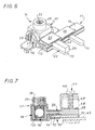
Si, tel que schématisé en traits interrompus sur la
figure 7, la borne de connexion 44 est du type à plaquette, la
superposition, à une dent 13 de la barre d'alimentation 11, du
tronçon d'extrémité 29 de la languette de conduction 22 de la
borne d'arrivée 10 suivant l'invention, se fait par en dessus.If, as shown in broken lines on the
FIG. 7, the
Ainsi qu'on le sait, une borne de connexion 44 à
plaquette comporte, comme précédemment, un élément de contact
fixe 45, mais la vis de serrage 46 associée engrène avec une
pièce fixe 47, qui peut par exemple être constituée par un
étrier entourant comme précédemment l'élément de contact fixe
45, et elle entraíne avec elle une plaquette 48, qui est passée
sous l'extrémité libre de son fût, et qu'elle a à charge de
rapprocher de l'élément de contact fixe 45, et les éléments à
serrer sont à engager entre cette plaquette 48 et cet élément
de contact fixe 45.As is known, a
Dans un tel cas, le prolongement latéral 36 inférieur
de l'enveloppe isolante 17 est détaché du prolongement latéral
35 supérieur et laissé ouvert.In such a case, the lower
Par exemple, et tel que représenté sur la figure 6, il
vient alors reposer latéralement sur la gaine isolante 14 de
la barre d'alimentation 11.For example, and as shown in Figure 6, there
then comes to rest laterally on the
Il est possible, ainsi, de minimiser la surépaisseur
E"2 à donner au tronçon d'extrémité 29 de la languette de
conduction 22 sur sa face principale 31 inférieure pour qu'il
puisse être au contact de la dent 13 concernée de la barre
d'alimentation 11.It is thus possible to minimize the excess thickness
E "2 to be given to the
C'est la raison pour laquelle cette surépaisseur E"2
est inférieure à la surépaisseur E'2 présente sur la face
principale 30 supérieure de ce tronçon d'extrémité 29.This is the reason why this extra thickness E "2
is less than the extra thickness E'2 present on the face
main upper 30 of this
Comme précédemment, le tronçon de racine 28 de la
languette de conduction 22 est avantageusement isolé dans sa
totalité, sur sa face supérieure, par le prolongement latéral
35 supérieur de l'enveloppe isolante 17, et, sur sa face
inférieure, par la barre d'alimentation 11.As before, the
Bien entendu, la présente invention ne se limite pas à la forme de réalisation décrite et représentée, mais englobe toute variante d'exécution.Of course, the present invention is not limited to the embodiment described and shown, but encompasses any variant of execution.
En particulier, le plot de connexion de la partie active peut ne comporter qu'une entrée de conducteur.In particular, the connection pad of the part active may have only one driver input.
Claims (8)
- An input terminal for a feed bar of a comb shape, in particular for modular electrical apparatuses, of the kind comprising an active conductive portion (16) comprising in itself on the one hand a connection stud (18) which, to permit engagement of an electrical conductor (19) to be connected, has at least one conductor entry (21), and, on the other hand, a conduction tongue (22) which is intended to be at least locally in superposed relationship with a tooth (13) of the feed bar (11) for contact therewith, characterised in that, the conduction tongue (22) of the active portion (16) comprising two parts (28, 29) in succession from the connection stud (18), namely a base part (28) and an end part (29), the end part (29) is of a thickness (E2) greater than that (E1) of the base part (28).
- An input terminal according to claim 1 characterised in that the end part (29) of the conduction tongue (22) comprises an additional thickness (E'2, E"2) on both of its two main faces (30, 31).
- An input terminal according to claim 2 characterised in that the additional thickness (E'2) on the upper main face (30) of the end part (29) of the conduction tongue (22) is greater than the additional thickness (E"2) on the lower main face (31).
- An input terminal according to any one of claims 1 to 3 characterised in that the conduction tongue (22) is generally rectilinear.
- An input terminal according to any one of claims 1 to 4 characterised in that it also comprises an insulating casing (17) which at least partly encloses the active portion (16), having an opening (20) in line with the conductor entry (21) thereof, and from which the conduction tongue (22) of said active portion (16) projects.
- An input terminal according to claim 5 characterised in that the insulating casing (17) comprises two lateral extensions (35, 36), one being an upper extension and the other a lower extension, by way of which it is capable of embracing the base part (28) of the conduction tongue (22) of the active portion (16).
- An input terminal according to claim 6 characterised in that the lower lateral extension (36) of the insulating casing (17) is pivoted to its upper lateral extension (35) by a hinge region (40) parallel to the conduction tongue (22) of the active portion (16).
- An input terminal according to either one of claims 6 and 7 characterised in that latching means are operatively disposed between the two lateral extensions (35, 36) of the insulating casing (17).
Applications Claiming Priority (2)
| Application Number | Priority Date | Filing Date | Title |
|---|---|---|---|
| FR9606994 | 1996-06-06 | ||
| FR9606994A FR2749709B1 (en) | 1996-06-06 | 1996-06-06 | INLET TERMINAL FOR COMB-SHAPED POWER BAR, ESPECIALLY FOR MODULAR ELECTRICAL APPLIANCES |
Publications (2)
| Publication Number | Publication Date |
|---|---|
| EP0812032A1 EP0812032A1 (en) | 1997-12-10 |
| EP0812032B1 true EP0812032B1 (en) | 2001-04-25 |
Family
ID=9492772
Family Applications (1)
| Application Number | Title | Priority Date | Filing Date |
|---|---|---|---|
| EP97401195A Expired - Lifetime EP0812032B1 (en) | 1996-06-06 | 1997-05-30 | Terminal for comb-shaped bus bar, especially for modular electrical apparatus |
Country Status (5)
| Country | Link |
|---|---|
| EP (1) | EP0812032B1 (en) |
| AT (1) | ATE200835T1 (en) |
| DE (1) | DE69704641T2 (en) |
| ES (1) | ES2155972T3 (en) |
| FR (1) | FR2749709B1 (en) |
Families Citing this family (3)
| Publication number | Priority date | Publication date | Assignee | Title |
|---|---|---|---|---|
| FR2817650B1 (en) * | 2000-12-06 | 2003-01-03 | Alstom | INSULATING PROTECTION WITH INTERLOCKING ELEMENTS FOR A LOW VOLTAGE CONNECTION TRANSITING HIGH CURRENTS |
| FR2907971B1 (en) * | 2006-10-27 | 2009-01-30 | Hager Electro S A S Soc Par Ac | CONNECTION DEVICE WITH TWO LEVELS OF CONNECTION FOR CONNECTING REINFORCEMENT SPOUT |
| DE102009016087A1 (en) * | 2009-04-03 | 2010-10-14 | Pollmann Elektrotechnik Gmbh | Busbar terminals construction |
Family Cites Families (6)
| Publication number | Priority date | Publication date | Assignee | Title |
|---|---|---|---|---|
| US2953771A (en) * | 1958-04-17 | 1960-09-20 | Square D Co | Electrical connector |
| FR2582451B1 (en) * | 1985-05-23 | 1987-07-03 | Merlin Gerin | CONNECTOR-TERMINAL FOR MODULAR DEVICES |
| US5064384A (en) * | 1990-12-04 | 1991-11-12 | Square D Company | Jumper assembly for multiple breaker application |
| US5201678A (en) * | 1991-11-06 | 1993-04-13 | Homac Mfg. Company | Set screw bus connector |
| FR2685563B1 (en) * | 1991-12-18 | 1994-05-20 | Legrand | OMNIBUS BAR FOR PARALLEL SUPPLY OF MODULAR ELECTRICAL APPLIANCES. |
| DE29502063U1 (en) * | 1995-02-09 | 1995-03-23 | Hager Electro Gmbh | Connector |
-
1996
- 1996-06-06 FR FR9606994A patent/FR2749709B1/en not_active Expired - Fee Related
-
1997
- 1997-05-30 ES ES97401195T patent/ES2155972T3/en not_active Expired - Lifetime
- 1997-05-30 AT AT97401195T patent/ATE200835T1/en not_active IP Right Cessation
- 1997-05-30 DE DE69704641T patent/DE69704641T2/en not_active Expired - Fee Related
- 1997-05-30 EP EP97401195A patent/EP0812032B1/en not_active Expired - Lifetime
Also Published As
| Publication number | Publication date |
|---|---|
| DE69704641D1 (en) | 2001-05-31 |
| ES2155972T3 (en) | 2001-06-01 |
| FR2749709B1 (en) | 1998-09-04 |
| ATE200835T1 (en) | 2001-05-15 |
| EP0812032A1 (en) | 1997-12-10 |
| FR2749709A1 (en) | 1997-12-12 |
| DE69704641T2 (en) | 2001-08-09 |
Similar Documents
| Publication | Publication Date | Title |
|---|---|---|
| EP0649195B1 (en) | Connection element comprising an insulating housing | |
| FR2642906A1 (en) | BARRETTE AT BORNES | |
| EP1916743B1 (en) | Electric device comprising at least one spring connection terminal | |
| EP0812032B1 (en) | Terminal for comb-shaped bus bar, especially for modular electrical apparatus | |
| EP0951096A1 (en) | Connection device and terminal fitted with such a device | |
| EP0772256A2 (en) | Electrical apparatus with connection terminals protected by a diaphragm attached with wings | |
| EP0148056B1 (en) | Universal clamp that cannot be lost for the realisation of electrical clamping connections between two conducting elements | |
| FR2552275A1 (en) | CONNECTOR FOR STARTER, IN PARTICULAR OF MOTOR VEHICLE | |
| FR2800519A1 (en) | Electrical connection block uses screws with initial part of thread slightly thickened such that they engage securely against vibration in transit but may be tightened on a conductor at point of use | |
| EP0817318B1 (en) | Terminal for comb-shaped bus bas especially for modular electrical apparatus | |
| EP1411590A2 (en) | Elastic connection terminal | |
| EP1610416B1 (en) | Electrical device adapted to cooperate with a horizontal comb-shaped bus bar | |
| EP1014414B1 (en) | Electrical apparatus like a circuit breaker or a modular switch | |
| EP1424756B1 (en) | Electrical connecting device of an electrical apparatus with a modular connecting comb or similar | |
| FR2795560A1 (en) | Electrical wire grip connection/touch proof cover mechanism having wire holder/clamping screw mechanism /holder with side/top protection cover clamping screw covering. | |
| FR2577075A1 (en) | Hybrid connection terminal for a printed circuit and an electronic apparatus equipped with such a terminal | |
| EP0961353B1 (en) | Connecting mechanism for a cable exit or derivation | |
| EP1065749B1 (en) | Connection accessory for electrical apparatus, in particular for modular electrical apparatus | |
| FR2772994A1 (en) | FEMALE ELECTRIC CONTACT MEMBER | |
| FR2776134A1 (en) | Electrical apparatus support mechanism | |
| FR2862441A1 (en) | ENLARGED TIGHTENING ROPE CABLE CLAMP AND JUNCTION BLOCK PROVIDED WITH SUCH A CABLE CLAMP | |
| FR2769418A1 (en) | CABLE CLAMP AND ELECTRIC APPARATUS PROVIDED WITH SUCH A CABLE CLAMP | |
| FR2667990A1 (en) | Connection terminal for a printed circuit, and printed circuit equipped with at least one such connection terminal | |
| FR2703845A1 (en) | Base socket. | |
| EP0837528B1 (en) | Terminal block |
Legal Events
| Date | Code | Title | Description |
|---|---|---|---|
| PUAI | Public reference made under article 153(3) epc to a published international application that has entered the european phase |
Free format text: ORIGINAL CODE: 0009012 |
|
| AK | Designated contracting states |
Kind code of ref document: A1 Designated state(s): AT BE DE ES GB IT |
|
| 17P | Request for examination filed |
Effective date: 19980110 |
|
| GRAG | Despatch of communication of intention to grant |
Free format text: ORIGINAL CODE: EPIDOS AGRA |
|
| GRAG | Despatch of communication of intention to grant |
Free format text: ORIGINAL CODE: EPIDOS AGRA |
|
| GRAH | Despatch of communication of intention to grant a patent |
Free format text: ORIGINAL CODE: EPIDOS IGRA |
|
| 17Q | First examination report despatched |
Effective date: 20001002 |
|
| GRAH | Despatch of communication of intention to grant a patent |
Free format text: ORIGINAL CODE: EPIDOS IGRA |
|
| GRAA | (expected) grant |
Free format text: ORIGINAL CODE: 0009210 |
|
| AK | Designated contracting states |
Kind code of ref document: B1 Designated state(s): AT BE DE ES GB IT |
|
| REF | Corresponds to: |
Ref document number: 200835 Country of ref document: AT Date of ref document: 20010515 Kind code of ref document: T |
|
| ITF | It: translation for a ep patent filed |
Owner name: FUMERO BREVETTI S.N.C. |
|
| GBT | Gb: translation of ep patent filed (gb section 77(6)(a)/1977) |
Effective date: 20010425 |
|
| REF | Corresponds to: |
Ref document number: 69704641 Country of ref document: DE Date of ref document: 20010531 |
|
| REG | Reference to a national code |
Ref country code: ES Ref legal event code: FG2A Ref document number: 2155972 Country of ref document: ES Kind code of ref document: T3 |
|
| REG | Reference to a national code |
Ref country code: GB Ref legal event code: IF02 |
|
| PLBE | No opposition filed within time limit |
Free format text: ORIGINAL CODE: 0009261 |
|
| STAA | Information on the status of an ep patent application or granted ep patent |
Free format text: STATUS: NO OPPOSITION FILED WITHIN TIME LIMIT |
|
| 26N | No opposition filed | ||
| PGFP | Annual fee paid to national office [announced via postgrant information from national office to epo] |
Ref country code: AT Payment date: 20050414 Year of fee payment: 9 |
|
| PGFP | Annual fee paid to national office [announced via postgrant information from national office to epo] |
Ref country code: DE Payment date: 20050510 Year of fee payment: 9 |
|
| PGFP | Annual fee paid to national office [announced via postgrant information from national office to epo] |
Ref country code: ES Payment date: 20050512 Year of fee payment: 9 |
|
| PGFP | Annual fee paid to national office [announced via postgrant information from national office to epo] |
Ref country code: GB Payment date: 20050517 Year of fee payment: 9 |
|
| PGFP | Annual fee paid to national office [announced via postgrant information from national office to epo] |
Ref country code: BE Payment date: 20050609 Year of fee payment: 9 |
|
| PG25 | Lapsed in a contracting state [announced via postgrant information from national office to epo] |
Ref country code: GB Free format text: LAPSE BECAUSE OF NON-PAYMENT OF DUE FEES Effective date: 20060530 Ref country code: AT Free format text: LAPSE BECAUSE OF NON-PAYMENT OF DUE FEES Effective date: 20060530 |
|
| PG25 | Lapsed in a contracting state [announced via postgrant information from national office to epo] |
Ref country code: ES Free format text: LAPSE BECAUSE OF NON-PAYMENT OF DUE FEES Effective date: 20060531 Ref country code: BE Free format text: LAPSE BECAUSE OF NON-PAYMENT OF DUE FEES Effective date: 20060531 |
|
| PGFP | Annual fee paid to national office [announced via postgrant information from national office to epo] |
Ref country code: IT Payment date: 20060531 Year of fee payment: 10 |
|
| PG25 | Lapsed in a contracting state [announced via postgrant information from national office to epo] |
Ref country code: DE Free format text: LAPSE BECAUSE OF NON-PAYMENT OF DUE FEES Effective date: 20061201 |
|
| GBPC | Gb: european patent ceased through non-payment of renewal fee |
Effective date: 20060530 |
|
| REG | Reference to a national code |
Ref country code: ES Ref legal event code: FD2A Effective date: 20060531 |
|
| BERE | Be: lapsed |
Owner name: *LEGRAND SNC Effective date: 20060531 Owner name: *LEGRAND Effective date: 20060531 |
|
| PG25 | Lapsed in a contracting state [announced via postgrant information from national office to epo] |
Ref country code: IT Free format text: LAPSE BECAUSE OF NON-PAYMENT OF DUE FEES Effective date: 20070530 |