EP0812032B1 - Anschlussbuchse für kammförmige Sammelschiene, insbesondere für modulare elektrische Geräte - Google Patents
Anschlussbuchse für kammförmige Sammelschiene, insbesondere für modulare elektrische Geräte Download PDFInfo
- Publication number
- EP0812032B1 EP0812032B1 EP97401195A EP97401195A EP0812032B1 EP 0812032 B1 EP0812032 B1 EP 0812032B1 EP 97401195 A EP97401195 A EP 97401195A EP 97401195 A EP97401195 A EP 97401195A EP 0812032 B1 EP0812032 B1 EP 0812032B1
- Authority
- EP
- European Patent Office
- Prior art keywords
- input terminal
- terminal according
- conduction tongue
- conduction
- active portion
- Prior art date
- Legal status (The legal status is an assumption and is not a legal conclusion. Google has not performed a legal analysis and makes no representation as to the accuracy of the status listed.)
- Expired - Lifetime
Links
- 239000004020 conductor Substances 0.000 claims abstract description 15
- 238000002513 implantation Methods 0.000 description 5
- 230000008901 benefit Effects 0.000 description 2
- 238000009413 insulation Methods 0.000 description 2
- 210000004027 cell Anatomy 0.000 description 1
- 238000009434 installation Methods 0.000 description 1
- 230000004048 modification Effects 0.000 description 1
- 238000012986 modification Methods 0.000 description 1
Images


Classifications
-
- H—ELECTRICITY
- H01—ELECTRIC ELEMENTS
- H01R—ELECTRICALLY-CONDUCTIVE CONNECTIONS; STRUCTURAL ASSOCIATIONS OF A PLURALITY OF MUTUALLY-INSULATED ELECTRICAL CONNECTING ELEMENTS; COUPLING DEVICES; CURRENT COLLECTORS
- H01R9/00—Structural associations of a plurality of mutually-insulated electrical connecting elements, e.g. terminal strips or terminal blocks; Terminals or binding posts mounted upon a base or in a case; Bases therefor
- H01R9/22—Bases, e.g. strip, block, panel
- H01R9/24—Terminal blocks
- H01R9/26—Clip-on terminal blocks for side-by-side rail- or strip-mounting
- H01R9/2675—Electrical interconnections between two blocks, e.g. by means of busbars
-
- H—ELECTRICITY
- H01—ELECTRIC ELEMENTS
- H01R—ELECTRICALLY-CONDUCTIVE CONNECTIONS; STRUCTURAL ASSOCIATIONS OF A PLURALITY OF MUTUALLY-INSULATED ELECTRICAL CONNECTING ELEMENTS; COUPLING DEVICES; CURRENT COLLECTORS
- H01R11/00—Individual connecting elements providing two or more spaced connecting locations for conductive members which are, or may be, thereby interconnected, e.g. end pieces for wires or cables supported by the wire or cable and having means for facilitating electrical connection to some other wire, terminal, or conductive member, blocks of binding posts
- H01R11/03—Individual connecting elements providing two or more spaced connecting locations for conductive members which are, or may be, thereby interconnected, e.g. end pieces for wires or cables supported by the wire or cable and having means for facilitating electrical connection to some other wire, terminal, or conductive member, blocks of binding posts characterised by the relationship between the connecting locations
- H01R11/07—Individual connecting elements providing two or more spaced connecting locations for conductive members which are, or may be, thereby interconnected, e.g. end pieces for wires or cables supported by the wire or cable and having means for facilitating electrical connection to some other wire, terminal, or conductive member, blocks of binding posts characterised by the relationship between the connecting locations the connecting locations being of the same type but different sizes
-
- H—ELECTRICITY
- H01—ELECTRIC ELEMENTS
- H01R—ELECTRICALLY-CONDUCTIVE CONNECTIONS; STRUCTURAL ASSOCIATIONS OF A PLURALITY OF MUTUALLY-INSULATED ELECTRICAL CONNECTING ELEMENTS; COUPLING DEVICES; CURRENT COLLECTORS
- H01R4/00—Electrically-conductive connections between two or more conductive members in direct contact, i.e. touching one another; Means for effecting or maintaining such contact; Electrically-conductive connections having two or more spaced connecting locations for conductors and using contact members penetrating insulation
- H01R4/28—Clamped connections, spring connections
- H01R4/30—Clamped connections, spring connections utilising a screw or nut clamping member
- H01R4/36—Conductive members located under tip of screw
Definitions
- the present invention relates generally comb-shaped power bars of the type implemented for example for the joint service of a plurality of modular electrical devices aligned side by side side by side on the same support.
- these bars feed comprise, transversely, from place to place, following a regular pitch, a plurality of teeth, through which they are suitable for engaging with the connection terminal concerned with these modular electrical devices or, at least, that of some of them.
- the present invention relates more particularly to the arrival terminal that is usual to associate with such a bar power supply to ensure its own connection to a electrical conductor capable of connecting it to any power supply.
- This arrival terminal includes, in particular, a part conductive active and this itself comprises, on the one hand, a connection pad, which, to allow the engagement of a electrical conductor to be connected, has at least one input conductor, and, on the other hand, a conduction tab, which especially when the sill of the power bar is protected by an insulating sheath, is intended to be superimpose, at least locally, on a tooth of this bar feed, for contact with this tooth and engagement spouse with her in the corresponding connection terminal any of the modular electrical appliances concerned.
- Arrival terminals of this type known to date generally have the disadvantage of offering no choice for the possibility of implantation of their tongue conduction with respect to the tooth of the power bar at which it must be superimposed, which limits in practice their field of application to this or that type of terminal for modular electrical devices concerned.
- the present invention generally has for object an incoming terminal for shaped power bar comb free from this drawback.
- This arrival terminal which is of the kind set out above, is generally characterized in that, the conduction tab of the active part comprising successively two sections from the connection pad, namely, a root segment and an end segment, the end section has a thickness greater than that of the root stretch.
- the conduction tab of the arrival terminal according to the invention can either overlap above or below a tooth on the bar supply, despite any thickness of insulation present on the sill of this power bar, and / or on its own root stretch.
- the arrival terminal according to the invention is suitable from as well in case the corresponding connection terminal of the modular electrical appliance concerned is a terminal of the type said to plate, that in case it is a terminal of the so-called elevator type, which advantageously increases by as much its scope, and which advantageously facilitates its reuse during a possible modification of the installation in which it operates.
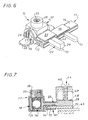
- the arrival terminal 10 is intended to be associated with a bar supply 11, which, in the general form of a comb, comprises, on the one hand, a sill 12, and, on the other hand, from transversely from place to place of this sill 12, following a regular step, teeth 13.
- a bar supply 11 which, in the general form of a comb, comprises, on the one hand, a sill 12, and, on the other hand, from transversely from place to place of this sill 12, following a regular step, teeth 13.
- the sill 12 of the power bar 11 is surrounded by a sheath insulating 14.
- the arrival terminal 10 comprises an active part 16, which is conductive, and which, in the embodiment shown, is at least partially coated with an insulating envelope 17.
- This active part 16 itself comprises, on the one hand, a connection pad 18, which, to allow the engagement of a electrical conductor 19 to be connected, present, at the right of a opening 20 of the insulating jacket 17, at least one entry conductor 21, and, on the other hand, a conduction tab 22, which, intended to overlap, at least locally, according to modalities described in more detail later, at a tooth 13 of the feed bar 11, for contact therewith, protrudes from the insulating jacket 17.
- the active part 16 also includes a screw clamp 23 intended to cooperate in screwing with a bore threaded 24 of the connection pad 18 which crosses transversely the conductor input 21 thereof.
- the stud connection 18 of the active part 16 has two inputs of conductor 21, and the insulating envelope 17 comprises, jointly, in correspondence, two openings 20.
- connection pad 18 extends on either side of its threaded bore 24, in both opening into this one, and so they're aligned back to back in an alignment direction D1 vis-à-vis from which the conduction tab 22 extends transversely.
- the alignment direction D1 of the two inputs of conductor 21 is perpendicular to the plane passing through this axis A and by this direction of elongation D2.
- the tongue conduction 22 of the active part 16 comprises, successively, from connection pad 18, two sections, namely, a root section 28, by which it is attached in one piece to this connection pad 18, and a end section 29, by which it is intended to come in contact with a tooth 13 of the feed bar 11.
- the root section 28 extends halfway up the stud connection 18, perpendicular to the corresponding face of it, along a width L1, which, in practice, is equal to that of this face.
- the end section 29 extends along a smaller width L2, while being centered relative to the root segment 28.
- this section end 29 a perpendicular to the following direction which it should be applied to a tooth 13 of the bar supply 11, a thickness E2 greater than that E1 of the root segment 28.
- the end section 29 comprises, with respect to the thickness E1 of the root section 28, an additional thickness E'2, E “2 on one and the other of its two main faces 30, 31, that is to say on both of the two faces which extend perpendicular to the direction in which it is intended to be superimposed on a tooth 13 of the bar supply 11.
- the extra thickness E'2 on the main face 30 upper end section 29 is greater than the extra thickness E "2 on its lower main face 31.
- the management according to which the end section 29 is intended to be superimposed on a tooth 13 of the feed bar 11 is parallel to the axis A of the threaded bore 24 of the connection pad 18.
- one and the other of these main faces 30, 31 are each connected respectively by a chamfer 32, 33 at the root section 28.
- the root section 28 has a rectangular outline elongated in the direction of alignment D1 of the conductor inputs 21 of the connection pad 18, while that the end section 29 has a substantially square contour.
- the tongue of conduction 22 is generally rectilinear.
- this conduction tab 22 is of a in one piece with the connection pad 18.
- the set can for example be very simply consisting of a section of profile duly cut and machined.
- the conduction tab 22 in fact of course protrudes, that, however, it includes two lateral extensions 35, 36, one upper, the other lower, by which it is able to enclose the section of root 28 of this conduction tab 22, that, to give access to the clamping screw 23, it comprises a well 38, and that each of its openings 20 is associated with a flap of closure 39.
- the lower lateral extension 36 of the insulating jacket 17 is articulated to its upper lateral extension 35 by a hinge zone 40 parallel to the conduction tab 22.
- these means on the one hand, projecting from the upper lateral extension 35, on the opposite side thereof at the lower lateral extension 36, a rib 41, and, on the other hand, projecting from the lateral extension 36 lower, on the side thereof opposite the lateral extension 35 upper, a tab 42, which, perforated in the shape of a handle, is suitable for hooking on rib 41.
- the conduction tab 22 of the part active 16 of the arrival terminal 10 according to the invention is superimposed, by its end section 29, on a tooth 13 of the power bar 11.
- connection terminal 44 in which the assembly must be engaged is of the elevator type, this superposition is made from below, i.e. on the side of the underside tooth 13 concerned of the feed bar 11.
- a connection terminal 44 of the type lift comprises, on the one hand, a contact element fixed 45, on which the clamping screw 46 is supported corresponding, and, on the other hand, a movable contact element 47, which, in the shape of a stirrup, surrounds the fixed contact element 45, and with which the clamping screw 46 meshes, and the elements to be clamped must be engaged between the element of fixed contact 45 and the strand of the movable contact element 47 opposite to that with which the clamping screw 46 meshes.
- the extra thickness E'2 that presents on its face main 30 upper the end section 29 of the conduction tab 22 allows the contact of this tab conduction 22 with tooth 13 of feed bar 11 despite the presence of insulation thicknesses due, on the one hand, to the insulating sheath 14 of the supply bar 11, and, on the other hand, to the upper lateral extension 35 of the insulating envelope 17 of the arrival terminal 10.
- the root segment 28 of the conduction tab 22 of the incoming terminal 10 is advantageously isolated in its entirety, on its upper face, by the feed bar 11 and by the lateral extension 35 upper of the insulating jacket 17, and, on its face lower, by the lower lateral extension 36 of this insulating envelope 17, for the benefit of security.
- connection terminal 44 is of the plate type, the superimposition, on a tooth 13 of the feed bar 11, of the end section 29 of the conduction tab 22 of the arrival terminal 10 according to the invention, is done from above.
- a connection terminal 44 to plate includes, as before, a contact element fixed 45, but the associated tightening screw 46 meshes with a fixed part 47, which can for example be constituted by a caliper surrounding as before the fixed contact element 45, and it carries with it a plate 48, which has passed under the free end of its barrel, and which it is responsible for move closer to the fixed contact element 45, and the elements to tighten are to be engaged between this plate 48 and this element fixed contact 45.
- the lower lateral extension 36 insulating jacket 17 is detached from the lateral extension 35 upper and left open.
- the root section 28 of the conduction tab 22 is advantageously insulated in its whole, on its upper face, by the lateral extension 35 upper of the insulating jacket 17, and, on its face lower, by the power bar 11.
- connection pad of the part active may have only one driver input.
Landscapes
- Connections Arranged To Contact A Plurality Of Conductors (AREA)
- Coupling Device And Connection With Printed Circuit (AREA)
- Connections By Means Of Piercing Elements, Nuts, Or Screws (AREA)
Claims (8)
- Versorgungsklemme für kammförmige Sammelschiene insbesondere für modulare elektrische Geräte, die einen leitenden aktiven Teil (16) besitzt, der einerseits ein Anschlussstück (18), das für die Einführung eines anzuschließenden elektrischen Leiters (19) mindestens einen Leitereintritt (21) aufweist, und andererseits eine Leitungszunge (22) besitzt, die dazu bestimmt ist, sich mindestens örtlich einem Zahn (13) der Sammelschiene (11) zu überlagern, um mit diesem in Kontakt zu kommen, dadurch gekennzeichnet, dass die Leitungszunge (22) des aktiven Teils (16) vom Anschlussstück (18) an nacheinander zwei Teilstükke (28, 29) aufweist, und zwar ein Wurzelteilstück (28) und ein Endteilstück (29), und dass das Endteilstück (29) eine Dicke (E2) hat, die größer als die Dicke (El) des Wurzelteilstücks (28) ist.
- Versorgungsklemme nach Anspruch 1, dadurch gekennzeichnet, dass das Endteilstück (29) der Leitungszunge (22) auf seinen beiden Hauptflächen (30, 31) eine Überdicke (E'2, E"2) aufweist.
- Versorgungsklemme nach Anspruch 2, dadurch gekennzeichnet, dass die Überdicke (E'2) auf der oberen Hauptfläche (30) des Endteilstücks (29) der Leitungszunge (22) größer als die Überdicke (E"2) auf seiner unteren Hauptfläche (31) ist.
- Versorgungsklemme nach einem der Ansprüche 1 bis 3, dadurch gekennzeichnet, dass die Leitungszunge (22) insgesamt geradlinig ist.
- Versorgungsklemme nach einem der Ansprüche 1 bis 4, dadurch gekennzeichnet, dass sie ferner eine isolierende Hülle (17) aufweist, die den aktiven Teil (16) mindestens teilweise umhüllt, wobei sie auf Höhe dessen Leitereintritts (21) eine Öffnung (20) aufweist, und aus der die Leitungszunge (22) dieses aktiven Teils (16) hervorsteht.
- Versorgungsklemme nach Anspruch 5, dadurch gekennzeichnet, dass die isolierende Hülle (17) zwei seitliche Verlängerungen (35, 36), eine obere und eine untere, aufweist, mit denen sie das Wurzelteilstück (28) der Leitungszunge (22) des aktiven Teils (16) umschließen kann.
- Versorgungsklemme nach Anspruch 6, dadurch gekennzeichnet, dass die untere seitliche Verlängerung (36) der isolierenden Hülle (17) an ihrer oberen seitlichen Verlängerung (35) über einen zur Leitungszunge (22) des aktiven Teils (16) parallelen Scharnierbereich (40) angelenkt ist.
- Versorgungsklemme nach einem der Ansprüche 6, 7, dadurch gekennzeichnet, dass zwischen den beiden seitlichen Verlängerungen (35, 36) der isolierenden Hülle (17) Einrastmittel vorgesehen sind.
Applications Claiming Priority (2)
| Application Number | Priority Date | Filing Date | Title |
|---|---|---|---|
| FR9606994 | 1996-06-06 | ||
| FR9606994A FR2749709B1 (fr) | 1996-06-06 | 1996-06-06 | Borne d'arrivee pour barre d'alimentation en forme de peigne notamment pour appareils electriques modulaires |
Publications (2)
| Publication Number | Publication Date |
|---|---|
| EP0812032A1 EP0812032A1 (de) | 1997-12-10 |
| EP0812032B1 true EP0812032B1 (de) | 2001-04-25 |
Family
ID=9492772
Family Applications (1)
| Application Number | Title | Priority Date | Filing Date |
|---|---|---|---|
| EP97401195A Expired - Lifetime EP0812032B1 (de) | 1996-06-06 | 1997-05-30 | Anschlussbuchse für kammförmige Sammelschiene, insbesondere für modulare elektrische Geräte |
Country Status (5)
| Country | Link |
|---|---|
| EP (1) | EP0812032B1 (de) |
| AT (1) | ATE200835T1 (de) |
| DE (1) | DE69704641T2 (de) |
| ES (1) | ES2155972T3 (de) |
| FR (1) | FR2749709B1 (de) |
Families Citing this family (3)
| Publication number | Priority date | Publication date | Assignee | Title |
|---|---|---|---|---|
| FR2817650B1 (fr) * | 2000-12-06 | 2003-01-03 | Alstom | Protection isolante a elements emboitables pour une connexion basse tension transitant de forts courants |
| FR2907971B1 (fr) * | 2006-10-27 | 2009-01-30 | Hager Electro S A S Soc Par Ac | Dispositif de pontage a deux niveaux de raccordement permettant la connexion de becs de repiquage |
| DE102009016087A1 (de) | 2009-04-03 | 2010-10-14 | Pollmann Elektrotechnik Gmbh | Sammelschienen-Anschlussklemmen-Konstruktion |
Family Cites Families (6)
| Publication number | Priority date | Publication date | Assignee | Title |
|---|---|---|---|---|
| US2953771A (en) * | 1958-04-17 | 1960-09-20 | Square D Co | Electrical connector |
| FR2582451B1 (fr) * | 1985-05-23 | 1987-07-03 | Merlin Gerin | Connecteur-barrette de raccordement pour des appareils modulaires |
| US5064384A (en) * | 1990-12-04 | 1991-11-12 | Square D Company | Jumper assembly for multiple breaker application |
| US5201678A (en) * | 1991-11-06 | 1993-04-13 | Homac Mfg. Company | Set screw bus connector |
| FR2685563B1 (fr) * | 1991-12-18 | 1994-05-20 | Legrand | Barre omnibus pour l'alimentation en parallele d'appareils electriques modulaires. |
| DE29502063U1 (de) * | 1995-02-09 | 1995-03-23 | Hager Electro GmbH, 66131 Saarbrücken | Anschlußklemme |
-
1996
- 1996-06-06 FR FR9606994A patent/FR2749709B1/fr not_active Expired - Fee Related
-
1997
- 1997-05-30 ES ES97401195T patent/ES2155972T3/es not_active Expired - Lifetime
- 1997-05-30 AT AT97401195T patent/ATE200835T1/de not_active IP Right Cessation
- 1997-05-30 EP EP97401195A patent/EP0812032B1/de not_active Expired - Lifetime
- 1997-05-30 DE DE69704641T patent/DE69704641T2/de not_active Expired - Fee Related
Also Published As
| Publication number | Publication date |
|---|---|
| DE69704641T2 (de) | 2001-08-09 |
| FR2749709A1 (fr) | 1997-12-12 |
| ES2155972T3 (es) | 2001-06-01 |
| DE69704641D1 (de) | 2001-05-31 |
| FR2749709B1 (fr) | 1998-09-04 |
| ATE200835T1 (de) | 2001-05-15 |
| EP0812032A1 (de) | 1997-12-10 |
Similar Documents
| Publication | Publication Date | Title |
|---|---|---|
| EP0649195B1 (de) | Verbindungselement mit Isoliergehäuse | |
| EP1916743B1 (de) | Elektrisches Gerät, das mindestens eine Federanschlussklemme umfasst | |
| EP0812032B1 (de) | Anschlussbuchse für kammförmige Sammelschiene, insbesondere für modulare elektrische Geräte | |
| EP0951096A1 (de) | Anschlussvorrichtung und Anschlussklemme ausgerüstet mit einer solchen Vorrichtung | |
| EP0772256A2 (de) | Elektrisches Gerät mit Anschlussklemmen geschützt dürch eine Blende verbindet mit Flügel | |
| EP0148056B1 (de) | Sich nicht lösende Universalklemme zur Realisierung von elektrischen Quetschverbindungen zwischen zwei leitenden Elementen | |
| FR2552275A1 (fr) | Connecteur pour demarreur, notamment de vehicule automobile | |
| FR2800519A1 (fr) | Assemblage formant borne pret a cabler comportant des vis de serrage resistantes aux vibrations | |
| EP0817318B1 (de) | Anschlussbuchse für kammförmige Sammelschiene, insbesondere für modulare elektrische Geräte | |
| EP1411590A2 (de) | Elastische Anschlussklemme | |
| EP1610416B1 (de) | Elektrisches Gerät angepast um mit einer kammförmigen Sammelschiene zusammenzuwirken | |
| EP1014414B1 (de) | Elektrisches Gerät wie ein Leistungsschalter oder ein moduläre Schalter | |
| EP1424756B1 (de) | Elektrische Verbindungsanordnung eines electrischen Apparates mit einem modularen Verbindungskamm oder ähnlich | |
| FR2795560A1 (fr) | Serre-fil muni d'un dispositif de protection contre le toucher | |
| FR2577075A1 (fr) | Borne de connexion mixte pour circuit imprime et appareil electronique equipe d'une telle borne | |
| EP0961353B1 (de) | Anschlussvorrichtung für einen Kabelausgang oder eine Abzweigung | |
| EP1065749B1 (de) | Verbindungszusatzgerät für elektrische Apparate, ins besondere für modulare elektrische Apparate | |
| FR2772994A1 (fr) | Organe de contact electrique femelle | |
| FR2776134A1 (fr) | Support d'appareillage a rapporter sur le socle d'une goulotte a retours diriges l'un vers l'autre | |
| FR2862441A1 (fr) | Serre-cable a plage de serrage elargie et bloc de jonction muni d'un tel serre-cable | |
| FR2667990A1 (fr) | Borne de connexion pour circuit imprime, et circuit imprime equipe d'au moins une telle borne de connexion. | |
| EP0779678B1 (de) | Elektrischer Kabelsteckverbinder zum Anschliessen an ein leitendes Teil | |
| FR2703845A1 (fr) | Socle de prise de courant. | |
| EP0837528B1 (de) | Anschlussleiste | |
| FR2779279A1 (fr) | Barre de distribution d'energie electrique |
Legal Events
| Date | Code | Title | Description |
|---|---|---|---|
| PUAI | Public reference made under article 153(3) epc to a published international application that has entered the european phase |
Free format text: ORIGINAL CODE: 0009012 |
|
| AK | Designated contracting states |
Kind code of ref document: A1 Designated state(s): AT BE DE ES GB IT |
|
| 17P | Request for examination filed |
Effective date: 19980110 |
|
| GRAG | Despatch of communication of intention to grant |
Free format text: ORIGINAL CODE: EPIDOS AGRA |
|
| GRAG | Despatch of communication of intention to grant |
Free format text: ORIGINAL CODE: EPIDOS AGRA |
|
| GRAH | Despatch of communication of intention to grant a patent |
Free format text: ORIGINAL CODE: EPIDOS IGRA |
|
| 17Q | First examination report despatched |
Effective date: 20001002 |
|
| GRAH | Despatch of communication of intention to grant a patent |
Free format text: ORIGINAL CODE: EPIDOS IGRA |
|
| GRAA | (expected) grant |
Free format text: ORIGINAL CODE: 0009210 |
|
| AK | Designated contracting states |
Kind code of ref document: B1 Designated state(s): AT BE DE ES GB IT |
|
| REF | Corresponds to: |
Ref document number: 200835 Country of ref document: AT Date of ref document: 20010515 Kind code of ref document: T |
|
| ITF | It: translation for a ep patent filed | ||
| GBT | Gb: translation of ep patent filed (gb section 77(6)(a)/1977) |
Effective date: 20010425 |
|
| REF | Corresponds to: |
Ref document number: 69704641 Country of ref document: DE Date of ref document: 20010531 |
|
| REG | Reference to a national code |
Ref country code: ES Ref legal event code: FG2A Ref document number: 2155972 Country of ref document: ES Kind code of ref document: T3 |
|
| REG | Reference to a national code |
Ref country code: GB Ref legal event code: IF02 |
|
| PLBE | No opposition filed within time limit |
Free format text: ORIGINAL CODE: 0009261 |
|
| STAA | Information on the status of an ep patent application or granted ep patent |
Free format text: STATUS: NO OPPOSITION FILED WITHIN TIME LIMIT |
|
| 26N | No opposition filed | ||
| PGFP | Annual fee paid to national office [announced via postgrant information from national office to epo] |
Ref country code: AT Payment date: 20050414 Year of fee payment: 9 |
|
| PGFP | Annual fee paid to national office [announced via postgrant information from national office to epo] |
Ref country code: DE Payment date: 20050510 Year of fee payment: 9 |
|
| PGFP | Annual fee paid to national office [announced via postgrant information from national office to epo] |
Ref country code: ES Payment date: 20050512 Year of fee payment: 9 |
|
| PGFP | Annual fee paid to national office [announced via postgrant information from national office to epo] |
Ref country code: GB Payment date: 20050517 Year of fee payment: 9 |
|
| PGFP | Annual fee paid to national office [announced via postgrant information from national office to epo] |
Ref country code: BE Payment date: 20050609 Year of fee payment: 9 |
|
| PG25 | Lapsed in a contracting state [announced via postgrant information from national office to epo] |
Ref country code: GB Free format text: LAPSE BECAUSE OF NON-PAYMENT OF DUE FEES Effective date: 20060530 Ref country code: AT Free format text: LAPSE BECAUSE OF NON-PAYMENT OF DUE FEES Effective date: 20060530 |
|
| PG25 | Lapsed in a contracting state [announced via postgrant information from national office to epo] |
Ref country code: ES Free format text: LAPSE BECAUSE OF NON-PAYMENT OF DUE FEES Effective date: 20060531 Ref country code: BE Free format text: LAPSE BECAUSE OF NON-PAYMENT OF DUE FEES Effective date: 20060531 |
|
| PGFP | Annual fee paid to national office [announced via postgrant information from national office to epo] |
Ref country code: IT Payment date: 20060531 Year of fee payment: 10 |
|
| PG25 | Lapsed in a contracting state [announced via postgrant information from national office to epo] |
Ref country code: DE Free format text: LAPSE BECAUSE OF NON-PAYMENT OF DUE FEES Effective date: 20061201 |
|
| GBPC | Gb: european patent ceased through non-payment of renewal fee |
Effective date: 20060530 |
|
| REG | Reference to a national code |
Ref country code: ES Ref legal event code: FD2A Effective date: 20060531 |
|
| BERE | Be: lapsed |
Owner name: *LEGRAND SNC Effective date: 20060531 Owner name: *LEGRAND Effective date: 20060531 |
|
| PG25 | Lapsed in a contracting state [announced via postgrant information from national office to epo] |
Ref country code: IT Free format text: LAPSE BECAUSE OF NON-PAYMENT OF DUE FEES Effective date: 20070530 |