EP0811564B1 - Conteneur multi usages perfectionné - Google Patents
Conteneur multi usages perfectionné Download PDFInfo
- Publication number
- EP0811564B1 EP0811564B1 EP97500102A EP97500102A EP0811564B1 EP 0811564 B1 EP0811564 B1 EP 0811564B1 EP 97500102 A EP97500102 A EP 97500102A EP 97500102 A EP97500102 A EP 97500102A EP 0811564 B1 EP0811564 B1 EP 0811564B1
- Authority
- EP
- European Patent Office
- Prior art keywords
- container
- anchors
- lifting
- bolts
- crane
- Prior art date
- Legal status (The legal status is an assumption and is not a legal conclusion. Google has not performed a legal analysis and makes no representation as to the accuracy of the status listed.)
- Expired - Lifetime
Links
Images


Classifications
-
- B—PERFORMING OPERATIONS; TRANSPORTING
- B65—CONVEYING; PACKING; STORING; HANDLING THIN OR FILAMENTARY MATERIAL
- B65F—GATHERING OR REMOVAL OF DOMESTIC OR LIKE REFUSE
- B65F1/00—Refuse receptacles; Accessories therefor
- B65F1/12—Refuse receptacles; Accessories therefor with devices facilitating emptying
-
- B—PERFORMING OPERATIONS; TRANSPORTING
- B65—CONVEYING; PACKING; STORING; HANDLING THIN OR FILAMENTARY MATERIAL
- B65F—GATHERING OR REMOVAL OF DOMESTIC OR LIKE REFUSE
- B65F3/00—Vehicles particularly adapted for collecting refuse
- B65F3/02—Vehicles particularly adapted for collecting refuse with means for discharging refuse receptacles thereinto
- B65F3/0203—Vehicles particularly adapted for collecting refuse with means for discharging refuse receptacles thereinto with crane-like mechanisms
Definitions
- the present invention relates to a container metal of the kind of those comprising a pyramidal body truncated reversed, superiorly open, and fit to be placed in the street, occupying approximately the space of a vehicle automobile, and normally serving as a temporary store for the supply of building materials or to receive debris or other waste material from any work.
- the loading function and unloading can only be done in the direction longitudinal and consequently the drive of the container from a parking space to the center of the for its loading, or viceversa for its implementation place, must be done manually if we want to avoid the risk of producing serious damage to vehicles parked in front of and behind the container.
- this type of conventional container forms an indivisible set compared to the support truck, in such a way that the vehicle is not used for any another type of task that is not the one of the displacement of metal containers of work.
- GB-A-2 188 029 discloses a container transportable to rectangular plane presenting to ends of the front and back of the pairs of trunnions and in the central area a pair of pads.
- a vehicle with lift arms connectable by slings to the trunnions of container; the arms can pivot on an axis longitudinal to perform the loading and unloading container from one or from one side of the vehicle.
- the container of the present invention presents externally a configuration equivalent to conventional, but its lashings have been modified to allow loading / unloading from the means of transport by means of a lifting crane hydraulically moving radially and allowing take the container from the truck and place it in a any lateral posicion with respect to the vehicle, any like taking back an empty container and stacking it on a another dwelling on the truck, and so on until reach the maximum height permitted by the requirements of road traffic.
- This container has two lashings hidden at the edge or perimetric fret that superiorly presents the container to its large base or mouth through which this container can be raised by means of two conventional tie-downs, preferably hydraulically or pneumatically actuated, can do the usual operations in this way lifting from the vehicle and laying on the ground, or viceversa.
- tie-ins are completed by at least one other pair, set up lower, hidden in the lower corners of the container and provided with means of axial and radial displacement, so that during lifting and lowering of the container said lashings are hidden inside a cavity arranged for this purpose, but when unloading the container, they are extracted outside and the container is suspended by grabbing it by means of the lower lashings and higher set up in the side opposite, such at the moment of the arrival of the container in to which it must be emptied, it is the vehicle itself carrying the crane that handles the containers, or at the dump, the upper lashing is released and during the lifting of the container seized exclusively by one of its angles lower it rocks and pours the entire content to the place where it was laid.
- tie-downs together with the lifting mechanisms and rotation of the crane included in the vehicle itself, provide the maximum functional capacity in any situation, whether in streets, places to reduced maneuverability, since these are zones of parking, dump, etc. They do so possible pouring and loading functions in all place, including the transport truck itself, allowing for example to empty the debris contents of the container on yourself and return the container to the same position at empty again, in a very short period of time. All this yields substantial benefits of order economic, transport or type professional, who make it worthy of protection requested.
- FIG. 1 represents a vehicle equipped with a crane for loading / unloading containers of the type described in the present invention.
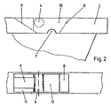
- Figure 2 shows in each detail view the tie-down points (4) placed higher on the container of the present invention.
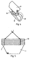
- Figure 3 shows in several views the stowage points (5) existing inferiorly in said container.
- Figure 4 shows a detail of one of the clamps hydraulic or pneumatic actuators the extreme of the crane (6).
- FIG. 5 represents an assembly produced by the simultaneous loading or unloading of several containers.
- the container multi-purpose use here includes a body (1) to truncated pyradimal configuration reversed, open superiorly and protected at its mouth by a profile peripheral (2).
- This container is suitable to be placed in the street, occupying approximately the equivalent space a motor vehicle while parked, or slightly lower.
- containers (1) of this type may be stacked between them for transport or storage then occupying a minimal space since the successive containers stacked on a container placed on the base, only raise the column to the extent corresponding to the thickness of the perimetrical band (2).
- this container (1) presents the pairs of lashings (4) and inferiorly in at least one angles, it presents another pair of tie-rods (5) of such that this container can be suspended from two ways according to the operations to be carried out with him.
- the usual or conventional form of operating consists in grasping the container by means of the two tie-downs superior (4) preferably consist of tongs hydraulic or pneumatic actuators, as are shown in Figure 4, which will be described more in detail below.
- This way of operating will be used to up and down the containerr from the vehicle on transporting to the ground, unless one realizes unloading operations of said container, and the case appropriate stowage to achieve is the one that is explained following.
- the container is subject in this case to lower lashings (5) and in the upper lashings (4) placed in the reverse side, the length of the chains or lashing cables being calculated in such a way that the container is also maintained in position horizontally to carry out loading operations or unloading.
- the purpose of this way of operating is to evidence when performing the pouring of the container, whether on the vehicle itself carrying the crane (6), either on the ground or on a pile of debris produced by previous unloadings; in these circumstances, and a container lying on the ground, hydraulic stowage or placed in the upper point (4) is released and one lifting the container subject exclusively to the lower lashing (5), so that it rocking and that it remains in a position almost reversed thus facilitating the total unloading of its contents previously chosen place.
- the truck (3) carrying out all these operations of loading / unloading is of the conventional type and it is equipped with a crane (6) which generally will have an arm vertical axis (61) with a rotational movement to orient the container in any position and this will facilitate its alignment in the street or in the vehicle.
- this crane will be provided with an arm (62) extendable telescopically, from another arm (63) articulated to the anterior with a variable angle using a other hydraulic piston and in turn a vertical arm (64) rotated to place the whole crane in any position by relative to the vehicle, even in front of the cab of it.
- the upper lashings (4) that were shown in detail in Figure 2 are located on the perimetric fret (2) which is a secissus reinforcement in grid welded to the sheet itself constituting the truncated pyramidal container (1). These links are defined by an upper window being framed laterally by two welded sheets (8) and (9), with angles tilt inward, communicating with a lower window (12) constituting a water evacuator or material that may have fallen within this zone.
- the stowage itself consists of a transverse bolt (4), around which are located the clamps (19-20) of the crane bridge (6).
- one of the zones with ramps (9) has corners or side implants (11), delimiting a central guide to through which the claw (19) is introduced while remaining in a vertical position, so that when the pneumatic actuation of the moving claw (20) around of the axis (4), this transverse bolt remains strongly seized (4) and therefore very little likely that a missed entry of it will occur.
- the lower lashings (5) just like the previous linkages are independent of those who are located on each side and mounted in a cavity (13) existing in the corresponding lower corner of the container (1).
- Each of these ties has a rod outside (15), mounted parallel in a bolt cross-section (14) which rotates relative to the container in stowing (16), while at the same time allowing axial from it to, from a hidden position to inside said cavity while the usual operations of the container subject exclusively by the upper stowages (4), to be able to extract it towards outside and by means of the rod (15) to subdue the container in this area by allowing rotation relative between said stowage and the container.
- Figure 4 shows one of the clips pneumatic or hydraulic actuator allowing the lifting the container by the upper points (4).
- a of these tongs (19) is fixed and is associated with a chain or cable (18) which at its other end is suspended from the corresponding crane (6).
- This clamp present itself an actuating cylinder (21) being associated with another movable clamp (20) in the form of hook, moving from an open position to a position closed by touching with the pliers (19) and with the space sufficient between the two to secure the bolt (4) constituent of the upper stowage.
- the cut (7) existing on the outer face of the grid or perimetral band (2) and located in the zone corresponding to the upper stowages (4) is intended to allow to gather by means of a sling (22) several between them, so that by means of the corresponding crane gangway placed in the tie-downs (4) container located above, a set of containers can be transported, either for its loading simultaneously in a vehicle, either for storage or his transport.
Landscapes
- Engineering & Computer Science (AREA)
- Mechanical Engineering (AREA)
- Loading Or Unloading Of Vehicles (AREA)
- Packages (AREA)
- Ship Loading And Unloading (AREA)
- Auxiliary Methods And Devices For Loading And Unloading (AREA)
- Filling Or Discharging Of Gas Storage Vessels (AREA)
Applications Claiming Priority (2)
| Application Number | Priority Date | Filing Date | Title |
|---|---|---|---|
| ES9601562U | 1996-06-07 | ||
| ES09601562U ES1034365Y (es) | 1996-06-07 | 1996-06-07 | Contenedor multiusos perfeccionado. |
Publications (3)
| Publication Number | Publication Date |
|---|---|
| EP0811564A2 EP0811564A2 (fr) | 1997-12-10 |
| EP0811564A3 EP0811564A3 (fr) | 1999-02-03 |
| EP0811564B1 true EP0811564B1 (fr) | 2005-09-07 |
Family
ID=8295479
Family Applications (1)
| Application Number | Title | Priority Date | Filing Date |
|---|---|---|---|
| EP97500102A Expired - Lifetime EP0811564B1 (fr) | 1996-06-07 | 1997-06-06 | Conteneur multi usages perfectionné |
Country Status (5)
| Country | Link |
|---|---|
| EP (1) | EP0811564B1 (es) |
| AT (1) | ATE303959T1 (es) |
| DE (1) | DE69734127T2 (es) |
| DK (1) | DK0811564T3 (es) |
| ES (1) | ES1034365Y (es) |
Families Citing this family (1)
| Publication number | Priority date | Publication date | Assignee | Title |
|---|---|---|---|---|
| GB0623232D0 (en) * | 2006-11-22 | 2007-01-03 | Dow Corning | Cementitious materials |
Family Cites Families (5)
| Publication number | Priority date | Publication date | Assignee | Title |
|---|---|---|---|---|
| FR1433139A (fr) * | 1965-05-07 | 1966-03-25 | Dispositif de décrochement automatique pour benne de manutention | |
| FR2593441B1 (fr) * | 1986-01-30 | 1988-04-29 | Bennes Marrel | Benne de transport et de chargement et vehicule routier pour sa manutention. |
| DE9317954U1 (de) * | 1993-11-24 | 1994-03-17 | Alustahl Behälterbau GmbH & Co KG, 28816 Stuhr | Aufbau für Nutzfahrzeuge |
| DE9319419U1 (de) * | 1993-12-17 | 1995-04-13 | Meul, Manfred, Dipl.-Ing., 53578 Windhagen | Absetzkippermulde |
| DE29502939U1 (de) * | 1995-02-22 | 1995-04-06 | J. Kresken GmbH & Co. KG, 40721 Hilden | Container für Schutt u.dgl. und Transportvorrichtung mit einem solchen Container |
-
1996
- 1996-06-07 ES ES09601562U patent/ES1034365Y/es not_active Expired - Fee Related
-
1997
- 1997-06-06 DK DK97500102T patent/DK0811564T3/da active
- 1997-06-06 EP EP97500102A patent/EP0811564B1/fr not_active Expired - Lifetime
- 1997-06-06 AT AT97500102T patent/ATE303959T1/de not_active IP Right Cessation
- 1997-06-06 DE DE69734127T patent/DE69734127T2/de not_active Expired - Lifetime
Also Published As
| Publication number | Publication date |
|---|---|
| ES1034365Y (es) | 1997-06-16 |
| DE69734127D1 (de) | 2005-10-13 |
| DE69734127T2 (de) | 2006-06-22 |
| EP0811564A3 (fr) | 1999-02-03 |
| EP0811564A2 (fr) | 1997-12-10 |
| ATE303959T1 (de) | 2005-09-15 |
| ES1034365U (es) | 1997-01-01 |
| DK0811564T3 (da) | 2006-01-23 |
Similar Documents
| Publication | Publication Date | Title |
|---|---|---|
| FR2577862A1 (fr) | Vehicule porteur pour soulever, transporter et deverser, par exemple une poche a crasses | |
| EP0199652B1 (fr) | Dispositif de manoeuvre de conteneur | |
| FR2916750A1 (fr) | Dispositif de manutention d'une charge telle qu'une bobine de toile. | |
| FR2687654A1 (fr) | Structure pour permettre de charger ou decharger des marchandises a transporter avec un dispositif de manutention a bras de levage hydraulique. | |
| FR2735430A1 (fr) | Benne et vehicule la comportant | |
| EP1885627B1 (fr) | Dispositif de couverture pour contenant de type benne, conteneur ou remorque. | |
| FR2459779A1 (fr) | Mecanisme de prehension et de levage pour conteneur | |
| EP0811564B1 (fr) | Conteneur multi usages perfectionné | |
| FR2593441A1 (fr) | Benne de transport et de chargement et vehicule routier pour sa manutention. | |
| CA2891969A1 (fr) | Vehicule de collecte de dechets avec leve-conteneurs ameliore | |
| LU81658A1 (fr) | Machine pour la pose de paves ou dalles en beton ou autre materiau | |
| WO2000003938A1 (fr) | Benne pour la collecte et le transport d'une charge du type dechets menagers | |
| EP2927160A1 (fr) | Benne de chantier passe-porte comportant un palonnier de manoeuvre escamotable et disposant d'une largeur réduite | |
| EP1022240B1 (fr) | Portique de securite pour pont basculeur | |
| FR2534201A1 (fr) | Dispositif de manutention d'un conteneur generalement allonge, en particulier d'un silo, et vehicule equipe d'un tel dispositif | |
| EP0077308B1 (fr) | Véhicule apte à l'auto-chargement, au creusage, au transport sur courtes distances et au creusement de matériaux inertes à hauteur variable | |
| EP1495994B1 (fr) | Déchetterie mobile | |
| FR2944512A1 (fr) | Caisse de benne et benne a ridelle laterale mobile pour le transport et/ou le stockage de charges | |
| EP1775157A1 (fr) | Ensemble de convoyage pour camion à benne | |
| FR2674810A1 (fr) | Chariot pour la manutention d'une charge equipee de roues. | |
| FR3037050A1 (fr) | Dispositif de chargement, d'elevation et de deversement de dechets dans une benne | |
| FR2563204A1 (fr) | Accessoire pour chariot a fourche, et procede de dechargement utilisant cet accessoire | |
| FR2824540A1 (fr) | Amelioration aux bennes de transport en vrac de residus | |
| FR2523047A1 (fr) | Dispositif de manutention pour le chargement, le dechargement et le bennage d'un conteneur | |
| EP0434880A1 (fr) | Dispositif de manutention d'une charge portée par un véhicule |
Legal Events
| Date | Code | Title | Description |
|---|---|---|---|
| PUAI | Public reference made under article 153(3) epc to a published international application that has entered the european phase |
Free format text: ORIGINAL CODE: 0009012 |
|
| AK | Designated contracting states |
Kind code of ref document: A2 Designated state(s): AT BE CH DE DK FR GB IT LI NL PT SE |
|
| RHK1 | Main classification (correction) |
Ipc: B65F 3/02 |
|
| PUAL | Search report despatched |
Free format text: ORIGINAL CODE: 0009013 |
|
| AK | Designated contracting states |
Kind code of ref document: A3 Designated state(s): AT BE CH DE DK ES FI FR GB GR IE IT LI LU MC NL PT SE |
|
| 17P | Request for examination filed |
Effective date: 19990219 |
|
| AKX | Designation fees paid |
Free format text: AT BE CH DE DK FR GB IT LI NL PT SE |
|
| 17Q | First examination report despatched |
Effective date: 20030704 |
|
| GRAP | Despatch of communication of intention to grant a patent |
Free format text: ORIGINAL CODE: EPIDOSNIGR1 |
|
| GRAS | Grant fee paid |
Free format text: ORIGINAL CODE: EPIDOSNIGR3 |
|
| GRAA | (expected) grant |
Free format text: ORIGINAL CODE: 0009210 |
|
| AK | Designated contracting states |
Kind code of ref document: B1 Designated state(s): AT BE CH DE DK FR GB IT LI NL PT SE |
|
| REG | Reference to a national code |
Ref country code: GB Ref legal event code: FG4D Free format text: NOT ENGLISH |
|
| REG | Reference to a national code |
Ref country code: CH Ref legal event code: EP |
|
| REF | Corresponds to: |
Ref document number: 69734127 Country of ref document: DE Date of ref document: 20051013 Kind code of ref document: P |
|
| REG | Reference to a national code |
Ref country code: CH Ref legal event code: NV Representative=s name: STRAHLBERG & PARTNERS PATENTANWAELTE |
|
| REG | Reference to a national code |
Ref country code: SE Ref legal event code: TRGR |
|
| REG | Reference to a national code |
Ref country code: DK Ref legal event code: T3 |
|
| GBT | Gb: translation of ep patent filed (gb section 77(6)(a)/1977) |
Effective date: 20060112 |
|
| PLBE | No opposition filed within time limit |
Free format text: ORIGINAL CODE: 0009261 |
|
| STAA | Information on the status of an ep patent application or granted ep patent |
Free format text: STATUS: NO OPPOSITION FILED WITHIN TIME LIMIT |
|
| 26N | No opposition filed |
Effective date: 20060608 |
|
| PGFP | Annual fee paid to national office [announced via postgrant information from national office to epo] |
Ref country code: PT Payment date: 20100527 Year of fee payment: 14 Ref country code: DK Payment date: 20100610 Year of fee payment: 14 |
|
| PGFP | Annual fee paid to national office [announced via postgrant information from national office to epo] |
Ref country code: AT Payment date: 20100614 Year of fee payment: 14 |
|
| PGFP | Annual fee paid to national office [announced via postgrant information from national office to epo] |
Ref country code: NL Payment date: 20100614 Year of fee payment: 14 Ref country code: CH Payment date: 20100623 Year of fee payment: 14 Ref country code: BE Payment date: 20100611 Year of fee payment: 14 |
|
| PGFP | Annual fee paid to national office [announced via postgrant information from national office to epo] |
Ref country code: SE Payment date: 20100614 Year of fee payment: 14 |
|
| PGFP | Annual fee paid to national office [announced via postgrant information from national office to epo] |
Ref country code: GB Payment date: 20110620 Year of fee payment: 15 |
|
| REG | Reference to a national code |
Ref country code: PT Ref legal event code: MM4A Free format text: LAPSE DUE TO NON-PAYMENT OF FEES Effective date: 20111206 |
|
| PGFP | Annual fee paid to national office [announced via postgrant information from national office to epo] |
Ref country code: IT Payment date: 20110625 Year of fee payment: 15 |
|
| BERE | Be: lapsed |
Owner name: *MENTO MARTIN FRANCO FELIX Effective date: 20110630 |
|
| REG | Reference to a national code |
Ref country code: NL Ref legal event code: V1 Effective date: 20120101 |
|
| PG25 | Lapsed in a contracting state [announced via postgrant information from national office to epo] |
Ref country code: PT Free format text: LAPSE BECAUSE OF NON-PAYMENT OF DUE FEES Effective date: 20111206 |
|
| REG | Reference to a national code |
Ref country code: CH Ref legal event code: PL |
|
| REG | Reference to a national code |
Ref country code: DK Ref legal event code: EBP |
|
| REG | Reference to a national code |
Ref country code: SE Ref legal event code: EUG |
|
| PG25 | Lapsed in a contracting state [announced via postgrant information from national office to epo] |
Ref country code: AT Free format text: LAPSE BECAUSE OF NON-PAYMENT OF DUE FEES Effective date: 20110606 |
|
| REG | Reference to a national code |
Ref country code: AT Ref legal event code: MM01 Ref document number: 303959 Country of ref document: AT Kind code of ref document: T Effective date: 20110606 |
|
| PG25 | Lapsed in a contracting state [announced via postgrant information from national office to epo] |
Ref country code: BE Free format text: LAPSE BECAUSE OF NON-PAYMENT OF DUE FEES Effective date: 20110630 |
|
| PG25 | Lapsed in a contracting state [announced via postgrant information from national office to epo] |
Ref country code: LI Free format text: LAPSE BECAUSE OF NON-PAYMENT OF DUE FEES Effective date: 20110630 Ref country code: CH Free format text: LAPSE BECAUSE OF NON-PAYMENT OF DUE FEES Effective date: 20110630 |
|
| PG25 | Lapsed in a contracting state [announced via postgrant information from national office to epo] |
Ref country code: NL Free format text: LAPSE BECAUSE OF NON-PAYMENT OF DUE FEES Effective date: 20120101 |
|
| PG25 | Lapsed in a contracting state [announced via postgrant information from national office to epo] |
Ref country code: DK Free format text: LAPSE BECAUSE OF NON-PAYMENT OF DUE FEES Effective date: 20110630 |
|
| PGFP | Annual fee paid to national office [announced via postgrant information from national office to epo] |
Ref country code: DE Payment date: 20120622 Year of fee payment: 16 |
|
| PGFP | Annual fee paid to national office [announced via postgrant information from national office to epo] |
Ref country code: FR Payment date: 20120705 Year of fee payment: 16 |
|
| GBPC | Gb: european patent ceased through non-payment of renewal fee |
Effective date: 20120606 |
|
| PG25 | Lapsed in a contracting state [announced via postgrant information from national office to epo] |
Ref country code: IT Free format text: LAPSE BECAUSE OF NON-PAYMENT OF DUE FEES Effective date: 20120606 |
|
| PG25 | Lapsed in a contracting state [announced via postgrant information from national office to epo] |
Ref country code: GB Free format text: LAPSE BECAUSE OF NON-PAYMENT OF DUE FEES Effective date: 20120606 Ref country code: SE Free format text: LAPSE BECAUSE OF NON-PAYMENT OF DUE FEES Effective date: 20110607 |
|
| REG | Reference to a national code |
Ref country code: DE Ref legal event code: R119 Ref document number: 69734127 Country of ref document: DE Effective date: 20140101 |
|
| REG | Reference to a national code |
Ref country code: FR Ref legal event code: ST Effective date: 20140228 |
|
| PG25 | Lapsed in a contracting state [announced via postgrant information from national office to epo] |
Ref country code: DE Free format text: LAPSE BECAUSE OF NON-PAYMENT OF DUE FEES Effective date: 20140101 |
|
| PG25 | Lapsed in a contracting state [announced via postgrant information from national office to epo] |
Ref country code: FR Free format text: LAPSE BECAUSE OF NON-PAYMENT OF DUE FEES Effective date: 20130701 |