EP0811564B1 - Multi-purpose container - Google Patents
Multi-purpose container Download PDFInfo
- Publication number
- EP0811564B1 EP0811564B1 EP97500102A EP97500102A EP0811564B1 EP 0811564 B1 EP0811564 B1 EP 0811564B1 EP 97500102 A EP97500102 A EP 97500102A EP 97500102 A EP97500102 A EP 97500102A EP 0811564 B1 EP0811564 B1 EP 0811564B1
- Authority
- EP
- European Patent Office
- Prior art keywords
- container
- anchors
- lifting
- bolts
- crane
- Prior art date
- Legal status (The legal status is an assumption and is not a legal conclusion. Google has not performed a legal analysis and makes no representation as to the accuracy of the status listed.)
- Expired - Lifetime
Links
Images


Classifications
-
- B—PERFORMING OPERATIONS; TRANSPORTING
- B65—CONVEYING; PACKING; STORING; HANDLING THIN OR FILAMENTARY MATERIAL
- B65F—GATHERING OR REMOVAL OF DOMESTIC OR LIKE REFUSE
- B65F1/00—Refuse receptacles; Accessories therefor
- B65F1/12—Refuse receptacles; Accessories therefor with devices facilitating emptying
-
- B—PERFORMING OPERATIONS; TRANSPORTING
- B65—CONVEYING; PACKING; STORING; HANDLING THIN OR FILAMENTARY MATERIAL
- B65F—GATHERING OR REMOVAL OF DOMESTIC OR LIKE REFUSE
- B65F3/00—Vehicles particularly adapted for collecting refuse
- B65F3/02—Vehicles particularly adapted for collecting refuse with means for discharging refuse receptacles thereinto
- B65F3/0203—Vehicles particularly adapted for collecting refuse with means for discharging refuse receptacles thereinto with crane-like mechanisms
Definitions
- the present invention relates to a container metal of the kind of those comprising a pyramidal body truncated reversed, superiorly open, and fit to be placed in the street, occupying approximately the space of a vehicle automobile, and normally serving as a temporary store for the supply of building materials or to receive debris or other waste material from any work.
- the loading function and unloading can only be done in the direction longitudinal and consequently the drive of the container from a parking space to the center of the for its loading, or viceversa for its implementation place, must be done manually if we want to avoid the risk of producing serious damage to vehicles parked in front of and behind the container.
- this type of conventional container forms an indivisible set compared to the support truck, in such a way that the vehicle is not used for any another type of task that is not the one of the displacement of metal containers of work.
- GB-A-2 188 029 discloses a container transportable to rectangular plane presenting to ends of the front and back of the pairs of trunnions and in the central area a pair of pads.
- a vehicle with lift arms connectable by slings to the trunnions of container; the arms can pivot on an axis longitudinal to perform the loading and unloading container from one or from one side of the vehicle.
- the container of the present invention presents externally a configuration equivalent to conventional, but its lashings have been modified to allow loading / unloading from the means of transport by means of a lifting crane hydraulically moving radially and allowing take the container from the truck and place it in a any lateral posicion with respect to the vehicle, any like taking back an empty container and stacking it on a another dwelling on the truck, and so on until reach the maximum height permitted by the requirements of road traffic.
- This container has two lashings hidden at the edge or perimetric fret that superiorly presents the container to its large base or mouth through which this container can be raised by means of two conventional tie-downs, preferably hydraulically or pneumatically actuated, can do the usual operations in this way lifting from the vehicle and laying on the ground, or viceversa.
- tie-ins are completed by at least one other pair, set up lower, hidden in the lower corners of the container and provided with means of axial and radial displacement, so that during lifting and lowering of the container said lashings are hidden inside a cavity arranged for this purpose, but when unloading the container, they are extracted outside and the container is suspended by grabbing it by means of the lower lashings and higher set up in the side opposite, such at the moment of the arrival of the container in to which it must be emptied, it is the vehicle itself carrying the crane that handles the containers, or at the dump, the upper lashing is released and during the lifting of the container seized exclusively by one of its angles lower it rocks and pours the entire content to the place where it was laid.
- tie-downs together with the lifting mechanisms and rotation of the crane included in the vehicle itself, provide the maximum functional capacity in any situation, whether in streets, places to reduced maneuverability, since these are zones of parking, dump, etc. They do so possible pouring and loading functions in all place, including the transport truck itself, allowing for example to empty the debris contents of the container on yourself and return the container to the same position at empty again, in a very short period of time. All this yields substantial benefits of order economic, transport or type professional, who make it worthy of protection requested.
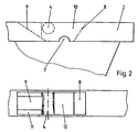
- FIG. 1 represents a vehicle equipped with a crane for loading / unloading containers of the type described in the present invention.
- Figure 2 shows in each detail view the tie-down points (4) placed higher on the container of the present invention.
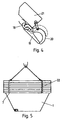
- Figure 3 shows in several views the stowage points (5) existing inferiorly in said container.
- Figure 4 shows a detail of one of the clamps hydraulic or pneumatic actuators the extreme of the crane (6).
- FIG. 5 represents an assembly produced by the simultaneous loading or unloading of several containers.
- the container multi-purpose use here includes a body (1) to truncated pyradimal configuration reversed, open superiorly and protected at its mouth by a profile peripheral (2).
- This container is suitable to be placed in the street, occupying approximately the equivalent space a motor vehicle while parked, or slightly lower.
- containers (1) of this type may be stacked between them for transport or storage then occupying a minimal space since the successive containers stacked on a container placed on the base, only raise the column to the extent corresponding to the thickness of the perimetrical band (2).
- this container (1) presents the pairs of lashings (4) and inferiorly in at least one angles, it presents another pair of tie-rods (5) of such that this container can be suspended from two ways according to the operations to be carried out with him.
- the usual or conventional form of operating consists in grasping the container by means of the two tie-downs superior (4) preferably consist of tongs hydraulic or pneumatic actuators, as are shown in Figure 4, which will be described more in detail below.
- This way of operating will be used to up and down the containerr from the vehicle on transporting to the ground, unless one realizes unloading operations of said container, and the case appropriate stowage to achieve is the one that is explained following.
- the container is subject in this case to lower lashings (5) and in the upper lashings (4) placed in the reverse side, the length of the chains or lashing cables being calculated in such a way that the container is also maintained in position horizontally to carry out loading operations or unloading.
- the purpose of this way of operating is to evidence when performing the pouring of the container, whether on the vehicle itself carrying the crane (6), either on the ground or on a pile of debris produced by previous unloadings; in these circumstances, and a container lying on the ground, hydraulic stowage or placed in the upper point (4) is released and one lifting the container subject exclusively to the lower lashing (5), so that it rocking and that it remains in a position almost reversed thus facilitating the total unloading of its contents previously chosen place.
- the truck (3) carrying out all these operations of loading / unloading is of the conventional type and it is equipped with a crane (6) which generally will have an arm vertical axis (61) with a rotational movement to orient the container in any position and this will facilitate its alignment in the street or in the vehicle.
- this crane will be provided with an arm (62) extendable telescopically, from another arm (63) articulated to the anterior with a variable angle using a other hydraulic piston and in turn a vertical arm (64) rotated to place the whole crane in any position by relative to the vehicle, even in front of the cab of it.
- the upper lashings (4) that were shown in detail in Figure 2 are located on the perimetric fret (2) which is a secissus reinforcement in grid welded to the sheet itself constituting the truncated pyramidal container (1). These links are defined by an upper window being framed laterally by two welded sheets (8) and (9), with angles tilt inward, communicating with a lower window (12) constituting a water evacuator or material that may have fallen within this zone.
- the stowage itself consists of a transverse bolt (4), around which are located the clamps (19-20) of the crane bridge (6).
- one of the zones with ramps (9) has corners or side implants (11), delimiting a central guide to through which the claw (19) is introduced while remaining in a vertical position, so that when the pneumatic actuation of the moving claw (20) around of the axis (4), this transverse bolt remains strongly seized (4) and therefore very little likely that a missed entry of it will occur.
- the lower lashings (5) just like the previous linkages are independent of those who are located on each side and mounted in a cavity (13) existing in the corresponding lower corner of the container (1).
- Each of these ties has a rod outside (15), mounted parallel in a bolt cross-section (14) which rotates relative to the container in stowing (16), while at the same time allowing axial from it to, from a hidden position to inside said cavity while the usual operations of the container subject exclusively by the upper stowages (4), to be able to extract it towards outside and by means of the rod (15) to subdue the container in this area by allowing rotation relative between said stowage and the container.
- Figure 4 shows one of the clips pneumatic or hydraulic actuator allowing the lifting the container by the upper points (4).
- a of these tongs (19) is fixed and is associated with a chain or cable (18) which at its other end is suspended from the corresponding crane (6).
- This clamp present itself an actuating cylinder (21) being associated with another movable clamp (20) in the form of hook, moving from an open position to a position closed by touching with the pliers (19) and with the space sufficient between the two to secure the bolt (4) constituent of the upper stowage.
- the cut (7) existing on the outer face of the grid or perimetral band (2) and located in the zone corresponding to the upper stowages (4) is intended to allow to gather by means of a sling (22) several between them, so that by means of the corresponding crane gangway placed in the tie-downs (4) container located above, a set of containers can be transported, either for its loading simultaneously in a vehicle, either for storage or his transport.
Landscapes
- Engineering & Computer Science (AREA)
- Mechanical Engineering (AREA)
- Loading Or Unloading Of Vehicles (AREA)
- Packages (AREA)
- Ship Loading And Unloading (AREA)
- Filling Or Discharging Of Gas Storage Vessels (AREA)
- Auxiliary Methods And Devices For Loading And Unloading (AREA)
Abstract
Description
La présente invention concerne un conteneur métallique du genre de ceux comprenant un corps pyramidal tronqué renversé, supérieurement ouvert, et apte à être placé dans la rue, occupant environ l'espace d'un véhicule automobile, et servant normalement de magasin temporaire pour l'approvisionnement de matériaux de construction ou pour recevoir des débris ou d'autres matériels de rebut provenant d'un ouvrage quelconque.The present invention relates to a container metal of the kind of those comprising a pyramidal body truncated reversed, superiorly open, and fit to be placed in the street, occupying approximately the space of a vehicle automobile, and normally serving as a temporary store for the supply of building materials or to receive debris or other waste material from any work.
Les conteneurs existants jusqu'à la date présentent cette constitution et sont transportés sur un véhicule spécial aménagé à cet effet en réalisant ses opérations de chargement et déchargement par relevage hydraulique arrière ou bien par entraínement et relevage arrière, alors l'espace d'occupation nécessaire pour descendre le conteneur du véhicule et le placer dans la place libre existante, ou vicéversa, est tout au moins l'addition des longitudes du véhicule et du conteneur, c'est à dire, au moins 10 mètres. La fonction de chargement et déchargement ne peut être réalisée que dans le sens longitudinal et par conséquent l'entraínement du conteneur à partir d'un espace de stationnement jusqu'au centre de la chaussée pour son chargement, ou vicéversa pour sa mise en place, doit être réalisée manuellement si l'on veut éviter le risque de produire de sérieux dégâts aux véhicules stationnés devant et derrière le conteneur.The existing containers until the date present this constitution and are transported on a special vehicle designed for this purpose by carrying out its loading and unloading operations by lifting hydraulic rear or by training and lifting back, then the space of occupation necessary for lower the container from the vehicle and place it in the existing free place, or viceversa, is at least the addition of the longitudes of the vehicle and the container, that is, at least 10 meters. The loading function and unloading can only be done in the direction longitudinal and consequently the drive of the container from a parking space to the center of the for its loading, or viceversa for its implementation place, must be done manually if we want to avoid the risk of producing serious damage to vehicles parked in front of and behind the container.
Lors du versage du contenu de l'un de ces conteneurs conventionnels il est nécessaire de le faire sur des surfaces de roulement sensiblement plates, pour des raisons de sécurité aussi bien du véhicule que de l'ouvrier. Cette façon d'opérer entraíne le fait que le contenu reste dispersé et répandu sur une surface étant toujours plus grande que celle du conteneur lui-même.When pouring the contents of one of these conventional containers it is necessary to do this on substantially flat rolling surfaces, for reasons of safety both for the vehicle and the the worker. This way of operating leads to the fact that the content remains dispersed and spread on a surface being always larger than that of the container itself.
Enfin, ce type de conteneurs conventionnels forme un ensemble indivisible par rapport au camion de support, de telle manière que le véhicule soit inutilisé pour tout autre type de tâches qui ne soit celle du déplacement de conteneurs métalliques d'ouvrage.Finally, this type of conventional container forms an indivisible set compared to the support truck, in such a way that the vehicle is not used for any another type of task that is not the one of the displacement of metal containers of work.
Le document GB-A-2 188 029 décrit un conteneur transportable à plan rectangulaire présentant aux extrémités de la partie avant et arrière des paires de tourillons et dans la zone centrale une paire de coussinets. Pour le levage du conteneur on dispose d'un véhicule présentant des bras élévateurs connectables par des élingues aux tourillons du conteneur; les bras peuvent pivoter sur un axe longitudinal pour effectuer la charge et la décharge du conteneur d'un ou depuis un côté du véhicule.GB-A-2 188 029 discloses a container transportable to rectangular plane presenting to ends of the front and back of the pairs of trunnions and in the central area a pair of pads. For the lifting of the container we have a vehicle with lift arms connectable by slings to the trunnions of container; the arms can pivot on an axis longitudinal to perform the loading and unloading container from one or from one side of the vehicle.
Le conteneur de la présente invention présente extérieurement une configuration équivalente aux conventionnels, mais ses arrimages ont été modifiés pour permettre son chargement/déchargement à partir du moyen de transport par l'intermédiaire d'une grue de relevage hydraulique se déplaçant radialement et permettant de prendre le conteneur du camion et de le placer dans une posicion latérale quelconque par rapport au véhicule, tout comme de reprendre un conteneur vide et de l'empiler sur un autre demeurant sur le camion, et ainsi de suite jusqu'à atteindre la hauteur maximale permise par les exigences de cirulation routière.The container of the present invention presents externally a configuration equivalent to conventional, but its lashings have been modified to allow loading / unloading from the means of transport by means of a lifting crane hydraulically moving radially and allowing take the container from the truck and place it in a any lateral posicion with respect to the vehicle, any like taking back an empty container and stacking it on a another dwelling on the truck, and so on until reach the maximum height permitted by the requirements of road traffic.
Ce conteneur est muni de deux arrimages supérieurs cachés au bord ou à la frette périmétral que présente supérieurement le conteneur à sa grande base ou embouchure à travers lesquels ce conteneur peut être soulevé au moyen de deux arrimages conventionnels, de préférence actionnés hydrauliquement ou pneumatiquement, en pouvant réaliser de cette façon les opérations habituelles de soulèvement à partir du véhicule et de la pose à terre, ou vicéversa. Ces arrimages sont complétés par au moins une autre paire, mis en place inférieurement, cachés dans les angles inférieurs du conteneur et munis de moyens de déplacement axial et radial, de tel manière que lors des opérations de soulèvement et de descente du conteneur lesdits arrimages sont cachés à l'intérieur d'une cavité aménagée à cet effet, mais lors du déchargement du récipient, ils sont extraits en dehors et le conteneur est suspendu en le saisissant au moyen des arrimages inférieurs et supérieurs mis en place dans le côté en regard, de telle manière qu'au moment de l'arrivée du conteneur au point auquel il doit être vidé, c'est le véhicule lui-même portant la grue qui manipule les conteneurs, ou à l'halde, l'arrimage supérieur est lâché et lors du soulèvement du conteneur saisi exclusivment par un de ses angles inférieurs il bascule et verse la totalité du contenu à l'endroit où il a été posé.This container has two lashings hidden at the edge or perimetric fret that superiorly presents the container to its large base or mouth through which this container can be raised by means of two conventional tie-downs, preferably hydraulically or pneumatically actuated, can do the usual operations in this way lifting from the vehicle and laying on the ground, or viceversa. These tie-ins are completed by at least one other pair, set up lower, hidden in the lower corners of the container and provided with means of axial and radial displacement, so that during lifting and lowering of the container said lashings are hidden inside a cavity arranged for this purpose, but when unloading the container, they are extracted outside and the container is suspended by grabbing it by means of the lower lashings and higher set up in the side opposite, such at the moment of the arrival of the container in to which it must be emptied, it is the vehicle itself carrying the crane that handles the containers, or at the dump, the upper lashing is released and during the lifting of the container seized exclusively by one of its angles lower it rocks and pours the entire content to the place where it was laid.
Ces arrimages, unis aux mécanismes de levage et de rotation de la grue inclus dans le véhicule lui-même, procurent la capacité maximale fonctionnelle en toute situation, que ce soit dans des rues, des endroits à manoeuvrabilité réduite, puisque'il s'agit de zones de stationnement, de décharge publique, etc... Ils font ainsi possibles les fonctions de versage et de chargement en tout lieu, y compris le camion de transport lui-même, permettant par exemple de vider le contenu de débris du conteneur sur soi-même et de retourner le conteneur à la même positon à nouveau vide, dans une période de temps très petite. Tout cela rapporte des avantages substantiels d'ordre économique, concernant le transport ou de type professionnel, qui le font être digne de la protection demandée.These tie-downs, together with the lifting mechanisms and rotation of the crane included in the vehicle itself, provide the maximum functional capacity in any situation, whether in streets, places to reduced maneuverability, since these are zones of parking, dump, etc. They do so possible pouring and loading functions in all place, including the transport truck itself, allowing for example to empty the debris contents of the container on yourself and return the container to the same position at empty again, in a very short period of time. All this yields substantial benefits of order economic, transport or type professional, who make it worthy of protection requested.
Ces caractéristiques et d'autres de la présente invention seront comprises plus facilement à l'aide de la description suivante réalisée sur la base d'un exemple pratique de réalisation; cette description est effectuée sur la base des dessins des plans ci-joint, où:These and other features of this invention will be understood more easily using the following description made on the basis of an example practical realization; this description is made based on the drawings of the attached plans, where:
La figure 1 représente un véhicule, muni d'une grue de chargement/déchargement de conteneurs du type décrit dans la présente invention.FIG. 1 represents a vehicle equipped with a crane for loading / unloading containers of the type described in the present invention.
La figure 2 représente dans chaque vue en détail les points d'arrimage (4) placés supérieurement sur le conteneur de la présente invention.Figure 2 shows in each detail view the tie-down points (4) placed higher on the container of the present invention.
La figure 3 représente dans plusieurs vues les points d'arrimage (5) existants inférieurement dans ledit conteneur.Figure 3 shows in several views the stowage points (5) existing inferiorly in said container.
La figure 4 représente un détail d'une des pinces d'actionnement hydraulique ou pneumatique existantes à l'extrême de la grue (6).Figure 4 shows a detail of one of the clamps hydraulic or pneumatic actuators the extreme of the crane (6).
La figure 5 représente un montage réalisé par le chargement ou déchargement simultané de plusieurs conteneurs.FIG. 5 represents an assembly produced by the simultaneous loading or unloading of several containers.
Comme il a été indiqué ci-devant le conteneur multi usages ici préconisé comprend un corps (1) à configuration pyradimale tronquée renversée, ouvert supérieurement et protégé à son embouchure par un profil périphérique (2). Ce conteneur est apte à être placé dans la rue, en occupant approximativement l'espace équivalant à un véhicule automobile lorsqu'il est stationné, ou légèrement inférieur. Etant donné sa configuration et sa structure, des conteneurs (1) de ce type peuvent être empilés succesivement entre eux pour leur transport ou stockage en occupant alors un espace minime puisque les conteneurs successifs empilés sur un conteneur placé sur la base, font seulement monter la colonne dans la mesure correspondante à l'épaisseur de la frette périmétrale (2).As indicated above the container multi-purpose use here includes a body (1) to truncated pyradimal configuration reversed, open superiorly and protected at its mouth by a profile peripheral (2). This container is suitable to be placed in the street, occupying approximately the equivalent space a motor vehicle while parked, or slightly lower. Given its configuration and its structure, containers (1) of this type may be stacked between them for transport or storage then occupying a minimal space since the successive containers stacked on a container placed on the base, only raise the column to the extent corresponding to the thickness of the perimetrical band (2).
Supérieurement ce conteneur (1) présente les paires d'arrimages (4) et inférieurement dans au moins un des angles, il présente une autre paire d'arrimages (5) de telle manière que ce conteneur peut être suspendu de deux façons en fonction des opérations à réaliser avec lui.Superiorly this container (1) presents the pairs of lashings (4) and inferiorly in at least one angles, it presents another pair of tie-rods (5) of such that this container can be suspended from two ways according to the operations to be carried out with him.
La forme habituelle ou conventionnelle d'opérer, consiste à saisir le conteneur au moyen des deux arrimages supérieurs (4) consistants de préférence à des pinces d'actionnement hydraulique ou pneumatique, tel qu'elles sont représentée dans la figure 4, qui seront décrites plus en détail ci-après. Cette façon d'opérer sera utilisée pour monter et descendre le conteneurr depuis le véhicule le transportant jusqu'au sol, à moins que l'on ne réalise des opérations de déchargement dudit conteneur, et le cas échéant l'arrimage à réaliser est celui que l'on explique à la suite.The usual or conventional form of operating, consists in grasping the container by means of the two tie-downs superior (4) preferably consist of tongs hydraulic or pneumatic actuators, as are shown in Figure 4, which will be described more in detail below. This way of operating will be used to up and down the containerr from the vehicle on transporting to the ground, unless one realizes unloading operations of said container, and the case appropriate stowage to achieve is the one that is explained following.
Le conteneur est assujeti dans ce cas dans les arrimages inférieurs (5) et dans les arrimages supérieurs (4) placés dans le côté inverse, la longueur des chaínes ou des câbles des arrimages étant calculée de telle manière que le conteneur se maintienne également en position horizontale pour réaliser les opérations de chargement ou déchargement. Le but de cette façon d'opérer est mise en évidence lors de la réalisation du versage du conteneur, que ce soit sur le véhicule lui-même portant la grue (6), soit par terre ou sur un tas de débris produits par des déchargements antérieurs; dans ces circonstances, et une fois le conteneur posé par terre, l'arrimage hydraulique ou pneumatique placé au point supérieur (4) est lâché et l'on procède au levage du conteneur assujeti exclusivement par l'arrimage inférieur (5), de telle façon que celui-ci bascule et qu'il demeure en position pratiquement renversée facilitant ainsi le déchargement total de son contenu au lieu préalablement choisi. The container is subject in this case to lower lashings (5) and in the upper lashings (4) placed in the reverse side, the length of the chains or lashing cables being calculated in such a way that the container is also maintained in position horizontally to carry out loading operations or unloading. The purpose of this way of operating is to evidence when performing the pouring of the container, whether on the vehicle itself carrying the crane (6), either on the ground or on a pile of debris produced by previous unloadings; in these circumstances, and a container lying on the ground, hydraulic stowage or placed in the upper point (4) is released and one lifting the container subject exclusively to the lower lashing (5), so that it rocking and that it remains in a position almost reversed thus facilitating the total unloading of its contents previously chosen place.
Le camion (3) réalisant toutes ces opérations de chargement/déchargement est du type conventionnel et il est muni d'une grue (6) qui généralement présentera un bras vertical (61) animé d'un mouvement de rotation permettant d'orienter le conteneur dans n'importe quelle position et cela facilitera son alignement dans la rue ou dans le véhicule. De préference, cette grue sera pourvue d'un bras (62) extensible téléscopiquement, d'un autre bras (63) articulé à l'antérieur avec un angle variable à l'aide d'un autre piston hydraulique et à son tour d'un bras vertical (64) animé d'un mouvement de rotation permettant de placer l'ensemble de la grue dans n'importe quelle position par rapport au véhicule, même par devant la cabine de celui-ci.The truck (3) carrying out all these operations of loading / unloading is of the conventional type and it is equipped with a crane (6) which generally will have an arm vertical axis (61) with a rotational movement to orient the container in any position and this will facilitate its alignment in the street or in the vehicle. Preferably, this crane will be provided with an arm (62) extendable telescopically, from another arm (63) articulated to the anterior with a variable angle using a other hydraulic piston and in turn a vertical arm (64) rotated to place the whole crane in any position by relative to the vehicle, even in front of the cab of it.
Les arrimages supérieurs (4) qui ont été représentés en détail dans la figure 2 sont situés sur la frette périmétrale (2) qui est un renforcement à sección en quadrillage soudé à la tôle elle-même constituant le conteneur pyramidal tronqué (1). Ces arrimages sont définis par une fenêtre supérieure étant encadrée latéralement par deux tôles soudées (8) et (9), avec des angles d'inclinaison vers l'intérieur, communiquant avec une fenêtre inférieure (12) constituant un évacuateur d'eau ou de matériels susceptibles d'être tombés à l'intérieur de cette zone. L'arrimage en lui-même est constitué d'un boulon transversal (4), autour duquel sont situées les pinces (19-20) de la passerelle de grue (6). De préférence, une des zones avec des rampes (9) présente des coins ou des impléments latéraux (11), délimitant un guide central à travers lequel la griffe (19) est introduite en demeurant alors en position verticale, de manière que lors de l'actionnement pneumatique de la griffe mobile (20) autour de l'axe (4), ce boulon transversal demeure toujours fortement saisi (4) et par conséquent il est très peu probable qu'une saisie manquée de celui-ci se produise. The upper lashings (4) that were shown in detail in Figure 2 are located on the perimetric fret (2) which is a sección reinforcement in grid welded to the sheet itself constituting the truncated pyramidal container (1). These links are defined by an upper window being framed laterally by two welded sheets (8) and (9), with angles tilt inward, communicating with a lower window (12) constituting a water evacuator or material that may have fallen within this zone. The stowage itself consists of a transverse bolt (4), around which are located the clamps (19-20) of the crane bridge (6). Preferably, one of the zones with ramps (9) has corners or side implants (11), delimiting a central guide to through which the claw (19) is introduced while remaining in a vertical position, so that when the pneumatic actuation of the moving claw (20) around of the axis (4), this transverse bolt remains strongly seized (4) and therefore very little likely that a missed entry of it will occur.
Les arrimages inférieurs (5), tout comme les arrimages antérieurs sont indépendants de ceux qui sont situés à chaque côté et qui sont montés dans une cavité (13) existante dans l'angle inférieur correspondant du conteneur (1). Chacun de ces arrimages présente une tige extérieure (15), montée parallèlement dans un boulon transversal (14), qui tourne par rapport au conteneur dans l'arrimage (16), en permettant en même temps un déplacement axial de celui-ci pour, en partant d'une position cachée à l'intérieur de ladite cavité tandis que l'on réalise les opérations habituelles du conteneur assujeti exclusivement par les arrimages supérieurs (4), pouvoir l'extraire vers l'extérieur et au moyen de la tige (15) assujétir le conteneur dans cette zone en permettant la rotation relative entre ledit arrimage et le conteneur. Ces arrimages (5), placés dans au moins un des angles inférieurs, sont cachés par une tôle (17) soudée par dessus et latéralement, écornant l'angle intérieur du conteneur (1) en évitant l'introduction de débris ou de matériels dans cette zone qui pourraient impossibiliter ou compliquer son fonctionnement.The lower lashings (5), just like the previous linkages are independent of those who are located on each side and mounted in a cavity (13) existing in the corresponding lower corner of the container (1). Each of these ties has a rod outside (15), mounted parallel in a bolt cross-section (14) which rotates relative to the container in stowing (16), while at the same time allowing axial from it to, from a hidden position to inside said cavity while the usual operations of the container subject exclusively by the upper stowages (4), to be able to extract it towards outside and by means of the rod (15) to subdue the container in this area by allowing rotation relative between said stowage and the container. These stowed (5), placed in at least one of the corners lower, are hidden by a sheet (17) welded from above and laterally, dehorning the inside corner of the container (1) avoiding the introduction of debris or material in this area that could be impossible or complicate its operation.
Cette configuration d'arrimages supérieurs (4) cachés et d'arrimages inférieurs (5) cachables, permet d'appliquer des conteneurs successifs sans que pour cela la hauteur d'empilement augmente de plus de l'épaisseur de la frette (2) d'un nouveau conteneur mis en place sur la pile.This configuration of upper lashings (4) concealed and lower (5) hinges, allows to apply successive containers without the stacking height increases by more than the thickness of the fret (2) of a new container put on the stack.
La figure 4 représente une des pinces d'actionnement pneumatique ou hydraulique permettant le soulèvement du conteneur par les points supérieurs (4). Une de ces pinces (19) est fixe et elle est associée à une chaíne ou un câble (18) qui par son autre extrémité est suspendu de la grue correspondante (6). Cette pince présente fixée à elle-même un cylindre d'actionnement (21) étant associé à une autre pince mobile (20) sous forme de crochet, se déplaçant d'une position ouverte à une position fermée en touchant avec la pince (19) et avec l'espace suffisant entre les deux pour assujétir le boulon (4) constitutif de l'arrimage supérieur.Figure 4 shows one of the clips pneumatic or hydraulic actuator allowing the lifting the container by the upper points (4). A of these tongs (19) is fixed and is associated with a chain or cable (18) which at its other end is suspended from the corresponding crane (6). This clamp present itself an actuating cylinder (21) being associated with another movable clamp (20) in the form of hook, moving from an open position to a position closed by touching with the pliers (19) and with the space sufficient between the two to secure the bolt (4) constituent of the upper stowage.
La coupe (7) existante sur la face extérieure du quadrillage ou frette périmetral (2) et située dans la zone correspondante aux arrimages supérieurs (4) a pour but de permettre réunir au moyen d'une élingue (22) plusieurs conteneurs entre eux, de manière qu'au moyen de la passerelle de grue correspondante placée dans les arrimages (4) du conteneur situé par dessus, un ensemble de conteneurs peut être transporté, soit pour son chargement simultanément dans un véhicule, soit pour son stockage ou son transport.The cut (7) existing on the outer face of the grid or perimetral band (2) and located in the zone corresponding to the upper stowages (4) is intended to allow to gather by means of a sling (22) several between them, so that by means of the corresponding crane gangway placed in the tie-downs (4) container located above, a set of containers can be transported, either for its loading simultaneously in a vehicle, either for storage or his transport.
Il n'est pas considéré nécessaire de faire cette description plus longue pour que tout expert en la matière comprenne l'envergure de l'invention et les avantages dérivés de celle-ci.It is not considered necessary to do this longer description for any subject matter expert understands the scope of the invention and the benefits derived from it.
Les termes de la rédaction de cette mémoire devront toujours être pris dans un sens large et non pas limitatif.The terms of writing this memoir should always be taken in a broad sense and not limiting.
Les matériels, forme et disposition des éléments seront susceptibles de variation si toutefois cela ne suppose pas une modification des caractéristiques essentielles de l'invention, qui sont revendiquées à la suite.The materials, shape and layout of the elements will be subject to variation if this is not does not assume a change in characteristics essential features of the invention, which are claimed in the after.
Claims (3)
- An improved multipurpose container of the type comprising an inverted truncated pyramidal-shaped body open at the upper portion, suitable for being placed in the street occupying approximately the space equivalent to a parked automobile, provided with a series of upper anchors for its lifting and lowering from a truck (3), provided with a crane (6), characterized in that said container (1) has a perimetral reinforcement (2) in the opening having two pairs of anchors (4) in the upper portion hidden inside said reinforcement, which allow the lifting and conventional handling of the container held by these four members; it also comprises, on at least one of the sides of the container and on its base, the rotating and removable side anchors (5), which also allow gripping the container through them and the pair of anchors (4) placed on the opposite side, and thus all this for, once the container has been placed on the ground and the corresponding upper anchors (4) have been released, making it overturn and emptying its content, whether in the truck (3) or on the ground, by lifting the container by the lower anchors (5).
- A container according to the previous claim, characterized in that the hidden upper anchors (4) are formed by a transverse bolt located between the walls defining the perimetral edge (2), which can be accessed from a wide upper window (10), demarcated by two tilted side plates (8) and (9), which communicate with another interior window (12) having unloading functions; and all this is thus to be able to stack consecutive containers due to the inexistence of projecting portions thereon.
- A container according to the previous claims, characterized in that the lower anchors (5) are independent from one another and are assembled in a cavity (13) existing in the corresponding angle of the container, each one of them having an anchor rod (15) laterally assembled in a bolt (14), which rotates in an anchor area (16) existing inside the container, allowing the axial displacement of the rod from the cavity (13) to the outside or vice versa (1), and the rotation of the rod (15) with respect to the container (1) during the overturning operations.
Applications Claiming Priority (2)
| Application Number | Priority Date | Filing Date | Title |
|---|---|---|---|
| ES09601562U ES1034365Y (en) | 1996-06-07 | 1996-06-07 | PERFECTED MULTIPURPOSE CONTAINER. |
| ES9601562U | 1996-06-07 |
Publications (3)
| Publication Number | Publication Date |
|---|---|
| EP0811564A2 EP0811564A2 (en) | 1997-12-10 |
| EP0811564A3 EP0811564A3 (en) | 1999-02-03 |
| EP0811564B1 true EP0811564B1 (en) | 2005-09-07 |
Family
ID=8295479
Family Applications (1)
| Application Number | Title | Priority Date | Filing Date |
|---|---|---|---|
| EP97500102A Expired - Lifetime EP0811564B1 (en) | 1996-06-07 | 1997-06-06 | Multi-purpose container |
Country Status (5)
| Country | Link |
|---|---|
| EP (1) | EP0811564B1 (en) |
| AT (1) | ATE303959T1 (en) |
| DE (1) | DE69734127T2 (en) |
| DK (1) | DK0811564T3 (en) |
| ES (1) | ES1034365Y (en) |
Families Citing this family (1)
| Publication number | Priority date | Publication date | Assignee | Title |
|---|---|---|---|---|
| GB0623232D0 (en) * | 2006-11-22 | 2007-01-03 | Dow Corning | Cementitious materials |
Family Cites Families (5)
| Publication number | Priority date | Publication date | Assignee | Title |
|---|---|---|---|---|
| FR1433139A (en) * | 1965-05-07 | 1966-03-25 | Automatic release device for handling bucket | |
| FR2593441B1 (en) * | 1986-01-30 | 1988-04-29 | Bennes Marrel | TRANSPORT AND LOADING BUCKET AND ROAD VEHICLE FOR HANDLING IT. |
| DE9317954U1 (en) * | 1993-11-24 | 1994-03-17 | Alustahl Behaelterbau Gmbh & C | Superstructure for commercial vehicles |
| DE9319419U1 (en) * | 1993-12-17 | 1995-04-13 | Meul Manfred Dipl Ing | Skip skip |
| DE29502939U1 (en) * | 1995-02-22 | 1995-04-06 | Kresken Gmbh & Co Kg J | Containers for rubble and the like and transport device with such a container |
-
1996
- 1996-06-07 ES ES09601562U patent/ES1034365Y/en not_active Expired - Fee Related
-
1997
- 1997-06-06 DK DK97500102T patent/DK0811564T3/en active
- 1997-06-06 EP EP97500102A patent/EP0811564B1/en not_active Expired - Lifetime
- 1997-06-06 DE DE69734127T patent/DE69734127T2/en not_active Expired - Lifetime
- 1997-06-06 AT AT97500102T patent/ATE303959T1/en not_active IP Right Cessation
Also Published As
| Publication number | Publication date |
|---|---|
| ES1034365Y (en) | 1997-06-16 |
| EP0811564A2 (en) | 1997-12-10 |
| EP0811564A3 (en) | 1999-02-03 |
| DE69734127T2 (en) | 2006-06-22 |
| DK0811564T3 (en) | 2006-01-23 |
| ES1034365U (en) | 1997-01-01 |
| DE69734127D1 (en) | 2005-10-13 |
| ATE303959T1 (en) | 2005-09-15 |
Similar Documents
| Publication | Publication Date | Title |
|---|---|---|
| FR2577862A1 (en) | CARRIER VEHICLE FOR LIFT, TRANSPORT AND DEVERSER, FOR EXAMPLE A CRASS POCKET | |
| EP0199652B1 (en) | Container-handling device | |
| FR2687654A1 (en) | STRUCTURE FOR ALLOWING LOADING OR UNLOADING OF GOODS FOR TRANSPORT WITH A HANDLING DEVICE WITH HYDRAULIC LIFTING ARM. | |
| FR2735430A1 (en) | TIPPER AND VEHICLE COMPRISING THE SAME | |
| EP1885627B1 (en) | Cover device for an open carrier, container or a trailer | |
| FR2459779A1 (en) | Container hoist with lifting frame - is actuated by hydraulic jacks operated in support frame with sliding central section | |
| EP0811564B1 (en) | Multi-purpose container | |
| FR2593441A1 (en) | TRANSPORT AND LOADING TANK AND ROAD VEHICLE FOR HANDLING. | |
| CA2891969A1 (en) | Rubbish collection vehicle with an improved container lifter | |
| LU81658A1 (en) | MACHINE FOR LAYING PAVES OR SLABS OF CONCRETE OR OTHER MATERIAL | |
| WO1996017750A1 (en) | Load hoisting and handling equipment associated with a vehicle | |
| WO2000003938A1 (en) | Tipper for collecting and transporting a load such as household refuse | |
| EP2927160A1 (en) | All-door construction skip comprising a retractable control spreader and having reduced width | |
| EP1022240B1 (en) | Safety gantry for bridge tipper | |
| FR2534201A1 (en) | Device for handling a generally elongated container, in particular a silo, and vehicle equipped with such a device. | |
| EP0077308B1 (en) | Vehicle for loading, excavating, transportation over short distances and for unloading materials at variable heights | |
| EP1495994B1 (en) | Mobile refuse collecter | |
| FR2944512A1 (en) | Case for trailer body of truck to transport and/or store loads i.e. bulk materials, has movable side member comprising concavity turned towards interior to direct masses loaded in direction of base wall in closed position | |
| EP1775157A1 (en) | Conveyor assembly for a tipping load vehicle | |
| FR2674810A1 (en) | Trolley for handling a load equipped with wheels | |
| FR3037050A1 (en) | DEVICE FOR LOADING, ELEVATING AND DISCHARGING WASTE INTO A DUMP | |
| FR2563204A1 (en) | ATTACHMENT FOR FORK TROLLEY, AND UNLOADING METHOD USING THE SAME | |
| FR2824540A1 (en) | Skip for transporting loose refuse has end wall made up of two flaps and handle, allowing it to be picked up, at opposite end, side walls sloping outwards, allowing skips to be stacked, one inside other | |
| FR2523047A1 (en) | Arm for loading skips onto lorry - comprises three pivotally interconnected sections which extend from lorry chassis | |
| EP0434880A1 (en) | Handling device for a load carried by a vehicle |
Legal Events
| Date | Code | Title | Description |
|---|---|---|---|
| PUAI | Public reference made under article 153(3) epc to a published international application that has entered the european phase |
Free format text: ORIGINAL CODE: 0009012 |
|
| AK | Designated contracting states |
Kind code of ref document: A2 Designated state(s): AT BE CH DE DK FR GB IT LI NL PT SE |
|
| RHK1 | Main classification (correction) |
Ipc: B65F 3/02 |
|
| PUAL | Search report despatched |
Free format text: ORIGINAL CODE: 0009013 |
|
| AK | Designated contracting states |
Kind code of ref document: A3 Designated state(s): AT BE CH DE DK ES FI FR GB GR IE IT LI LU MC NL PT SE |
|
| 17P | Request for examination filed |
Effective date: 19990219 |
|
| AKX | Designation fees paid |
Free format text: AT BE CH DE DK FR GB IT LI NL PT SE |
|
| 17Q | First examination report despatched |
Effective date: 20030704 |
|
| GRAP | Despatch of communication of intention to grant a patent |
Free format text: ORIGINAL CODE: EPIDOSNIGR1 |
|
| GRAS | Grant fee paid |
Free format text: ORIGINAL CODE: EPIDOSNIGR3 |
|
| GRAA | (expected) grant |
Free format text: ORIGINAL CODE: 0009210 |
|
| AK | Designated contracting states |
Kind code of ref document: B1 Designated state(s): AT BE CH DE DK FR GB IT LI NL PT SE |
|
| REG | Reference to a national code |
Ref country code: GB Ref legal event code: FG4D Free format text: NOT ENGLISH |
|
| REG | Reference to a national code |
Ref country code: CH Ref legal event code: EP |
|
| REF | Corresponds to: |
Ref document number: 69734127 Country of ref document: DE Date of ref document: 20051013 Kind code of ref document: P |
|
| REG | Reference to a national code |
Ref country code: CH Ref legal event code: NV Representative=s name: STRAHLBERG & PARTNERS PATENTANWAELTE |
|
| REG | Reference to a national code |
Ref country code: SE Ref legal event code: TRGR |
|
| REG | Reference to a national code |
Ref country code: DK Ref legal event code: T3 |
|
| GBT | Gb: translation of ep patent filed (gb section 77(6)(a)/1977) |
Effective date: 20060112 |
|
| PLBE | No opposition filed within time limit |
Free format text: ORIGINAL CODE: 0009261 |
|
| STAA | Information on the status of an ep patent application or granted ep patent |
Free format text: STATUS: NO OPPOSITION FILED WITHIN TIME LIMIT |
|
| 26N | No opposition filed |
Effective date: 20060608 |
|
| PGFP | Annual fee paid to national office [announced via postgrant information from national office to epo] |
Ref country code: PT Payment date: 20100527 Year of fee payment: 14 Ref country code: DK Payment date: 20100610 Year of fee payment: 14 |
|
| PGFP | Annual fee paid to national office [announced via postgrant information from national office to epo] |
Ref country code: AT Payment date: 20100614 Year of fee payment: 14 |
|
| PGFP | Annual fee paid to national office [announced via postgrant information from national office to epo] |
Ref country code: NL Payment date: 20100614 Year of fee payment: 14 Ref country code: CH Payment date: 20100623 Year of fee payment: 14 Ref country code: BE Payment date: 20100611 Year of fee payment: 14 |
|
| PGFP | Annual fee paid to national office [announced via postgrant information from national office to epo] |
Ref country code: SE Payment date: 20100614 Year of fee payment: 14 |
|
| PGFP | Annual fee paid to national office [announced via postgrant information from national office to epo] |
Ref country code: GB Payment date: 20110620 Year of fee payment: 15 |
|
| REG | Reference to a national code |
Ref country code: PT Ref legal event code: MM4A Free format text: LAPSE DUE TO NON-PAYMENT OF FEES Effective date: 20111206 |
|
| PGFP | Annual fee paid to national office [announced via postgrant information from national office to epo] |
Ref country code: IT Payment date: 20110625 Year of fee payment: 15 |
|
| BERE | Be: lapsed |
Owner name: *MENTO MARTIN FRANCO FELIX Effective date: 20110630 |
|
| REG | Reference to a national code |
Ref country code: NL Ref legal event code: V1 Effective date: 20120101 |
|
| PG25 | Lapsed in a contracting state [announced via postgrant information from national office to epo] |
Ref country code: PT Free format text: LAPSE BECAUSE OF NON-PAYMENT OF DUE FEES Effective date: 20111206 |
|
| REG | Reference to a national code |
Ref country code: CH Ref legal event code: PL |
|
| REG | Reference to a national code |
Ref country code: DK Ref legal event code: EBP |
|
| REG | Reference to a national code |
Ref country code: SE Ref legal event code: EUG |
|
| PG25 | Lapsed in a contracting state [announced via postgrant information from national office to epo] |
Ref country code: AT Free format text: LAPSE BECAUSE OF NON-PAYMENT OF DUE FEES Effective date: 20110606 |
|
| REG | Reference to a national code |
Ref country code: AT Ref legal event code: MM01 Ref document number: 303959 Country of ref document: AT Kind code of ref document: T Effective date: 20110606 |
|
| PG25 | Lapsed in a contracting state [announced via postgrant information from national office to epo] |
Ref country code: BE Free format text: LAPSE BECAUSE OF NON-PAYMENT OF DUE FEES Effective date: 20110630 |
|
| PG25 | Lapsed in a contracting state [announced via postgrant information from national office to epo] |
Ref country code: LI Free format text: LAPSE BECAUSE OF NON-PAYMENT OF DUE FEES Effective date: 20110630 Ref country code: CH Free format text: LAPSE BECAUSE OF NON-PAYMENT OF DUE FEES Effective date: 20110630 |
|
| PG25 | Lapsed in a contracting state [announced via postgrant information from national office to epo] |
Ref country code: NL Free format text: LAPSE BECAUSE OF NON-PAYMENT OF DUE FEES Effective date: 20120101 |
|
| PG25 | Lapsed in a contracting state [announced via postgrant information from national office to epo] |
Ref country code: DK Free format text: LAPSE BECAUSE OF NON-PAYMENT OF DUE FEES Effective date: 20110630 |
|
| PGFP | Annual fee paid to national office [announced via postgrant information from national office to epo] |
Ref country code: DE Payment date: 20120622 Year of fee payment: 16 |
|
| PGFP | Annual fee paid to national office [announced via postgrant information from national office to epo] |
Ref country code: FR Payment date: 20120705 Year of fee payment: 16 |
|
| GBPC | Gb: european patent ceased through non-payment of renewal fee |
Effective date: 20120606 |
|
| PG25 | Lapsed in a contracting state [announced via postgrant information from national office to epo] |
Ref country code: IT Free format text: LAPSE BECAUSE OF NON-PAYMENT OF DUE FEES Effective date: 20120606 |
|
| PG25 | Lapsed in a contracting state [announced via postgrant information from national office to epo] |
Ref country code: GB Free format text: LAPSE BECAUSE OF NON-PAYMENT OF DUE FEES Effective date: 20120606 Ref country code: SE Free format text: LAPSE BECAUSE OF NON-PAYMENT OF DUE FEES Effective date: 20110607 |
|
| REG | Reference to a national code |
Ref country code: DE Ref legal event code: R119 Ref document number: 69734127 Country of ref document: DE Effective date: 20140101 |
|
| REG | Reference to a national code |
Ref country code: FR Ref legal event code: ST Effective date: 20140228 |
|
| PG25 | Lapsed in a contracting state [announced via postgrant information from national office to epo] |
Ref country code: DE Free format text: LAPSE BECAUSE OF NON-PAYMENT OF DUE FEES Effective date: 20140101 |
|
| PG25 | Lapsed in a contracting state [announced via postgrant information from national office to epo] |
Ref country code: FR Free format text: LAPSE BECAUSE OF NON-PAYMENT OF DUE FEES Effective date: 20130701 |