EP0811446B1 - Stranggusskokille - Google Patents
Stranggusskokille Download PDFInfo
- Publication number
- EP0811446B1 EP0811446B1 EP96810369A EP96810369A EP0811446B1 EP 0811446 B1 EP0811446 B1 EP 0811446B1 EP 96810369 A EP96810369 A EP 96810369A EP 96810369 A EP96810369 A EP 96810369A EP 0811446 B1 EP0811446 B1 EP 0811446B1
- Authority
- EP
- European Patent Office
- Prior art keywords
- mould
- mold
- zone
- continuous casting
- lubricant
- Prior art date
- Legal status (The legal status is an assumption and is not a legal conclusion. Google has not performed a legal analysis and makes no representation as to the accuracy of the status listed.)
- Expired - Lifetime
Links
- 238000009749 continuous casting Methods 0.000 title claims abstract description 81
- 239000000463 material Substances 0.000 claims abstract description 74
- 239000000314 lubricant Substances 0.000 claims abstract description 65
- 210000001787 dendrite Anatomy 0.000 claims abstract description 15
- 238000000034 method Methods 0.000 claims abstract description 12
- 230000009974 thixotropic effect Effects 0.000 claims abstract description 11
- 239000002245 particle Substances 0.000 claims abstract description 9
- 238000005266 casting Methods 0.000 claims abstract description 5
- 238000007493 shaping process Methods 0.000 claims abstract description 3
- 239000002826 coolant Substances 0.000 claims description 56
- 238000001816 cooling Methods 0.000 claims description 12
- 238000012545 processing Methods 0.000 claims description 7
- 239000007787 solid Substances 0.000 claims description 6
- OKTJSMMVPCPJKN-UHFFFAOYSA-N Carbon Chemical compound [C] OKTJSMMVPCPJKN-UHFFFAOYSA-N 0.000 claims description 5
- 239000000919 ceramic Substances 0.000 claims description 4
- 238000007711 solidification Methods 0.000 claims description 4
- 230000008023 solidification Effects 0.000 claims description 4
- 230000009471 action Effects 0.000 claims description 3
- 239000010439 graphite Substances 0.000 claims description 3
- 229910002804 graphite Inorganic materials 0.000 claims description 3
- 239000011148 porous material Substances 0.000 claims description 3
- 238000010924 continuous production Methods 0.000 claims description 2
- 230000006698 induction Effects 0.000 claims description 2
- 230000005405 multipole Effects 0.000 claims description 2
- VYPSYNLAJGMNEJ-UHFFFAOYSA-N Silicium dioxide Chemical compound O=[Si]=O VYPSYNLAJGMNEJ-UHFFFAOYSA-N 0.000 claims 2
- 238000013019 agitation Methods 0.000 claims 1
- PNEYBMLMFCGWSK-UHFFFAOYSA-N aluminium oxide Inorganic materials [O-2].[O-2].[O-2].[Al+3].[Al+3] PNEYBMLMFCGWSK-UHFFFAOYSA-N 0.000 claims 1
- 229910052681 coesite Inorganic materials 0.000 claims 1
- 229910052593 corundum Inorganic materials 0.000 claims 1
- 229910052906 cristobalite Inorganic materials 0.000 claims 1
- 229910052500 inorganic mineral Inorganic materials 0.000 claims 1
- 239000011707 mineral Substances 0.000 claims 1
- 239000000377 silicon dioxide Substances 0.000 claims 1
- 229910052682 stishovite Inorganic materials 0.000 claims 1
- 229910052905 tridymite Inorganic materials 0.000 claims 1
- 229910001845 yogo sapphire Inorganic materials 0.000 claims 1
- 238000003756 stirring Methods 0.000 description 27
- 229910045601 alloy Inorganic materials 0.000 description 11
- 239000000956 alloy Substances 0.000 description 11
- XAGFODPZIPBFFR-UHFFFAOYSA-N aluminium Chemical compound [Al] XAGFODPZIPBFFR-UHFFFAOYSA-N 0.000 description 10
- 229910052782 aluminium Inorganic materials 0.000 description 8
- 238000009826 distribution Methods 0.000 description 8
- 238000004519 manufacturing process Methods 0.000 description 8
- 229910052751 metal Inorganic materials 0.000 description 8
- 239000002184 metal Substances 0.000 description 8
- 229910000838 Al alloy Inorganic materials 0.000 description 6
- 238000005299 abrasion Methods 0.000 description 6
- 230000008569 process Effects 0.000 description 6
- 230000000694 effects Effects 0.000 description 5
- 229910001092 metal group alloy Inorganic materials 0.000 description 5
- RYGMFSIKBFXOCR-UHFFFAOYSA-N Copper Chemical compound [Cu] RYGMFSIKBFXOCR-UHFFFAOYSA-N 0.000 description 4
- 230000015572 biosynthetic process Effects 0.000 description 4
- 229910052802 copper Inorganic materials 0.000 description 4
- 239000010949 copper Substances 0.000 description 4
- 238000013461 design Methods 0.000 description 4
- 238000006073 displacement reaction Methods 0.000 description 3
- 150000002739 metals Chemical class 0.000 description 3
- 238000007789 sealing Methods 0.000 description 3
- FYYHWMGAXLPEAU-UHFFFAOYSA-N Magnesium Chemical compound [Mg] FYYHWMGAXLPEAU-UHFFFAOYSA-N 0.000 description 2
- 229910000861 Mg alloy Inorganic materials 0.000 description 2
- 229910000831 Steel Inorganic materials 0.000 description 2
- 238000004140 cleaning Methods 0.000 description 2
- 238000010276 construction Methods 0.000 description 2
- 238000005242 forging Methods 0.000 description 2
- 230000017525 heat dissipation Effects 0.000 description 2
- 238000003780 insertion Methods 0.000 description 2
- 230000037431 insertion Effects 0.000 description 2
- 239000007788 liquid Substances 0.000 description 2
- 229910052749 magnesium Inorganic materials 0.000 description 2
- 239000011777 magnesium Substances 0.000 description 2
- 239000002557 mineral fiber Substances 0.000 description 2
- 239000002994 raw material Substances 0.000 description 2
- 238000010008 shearing Methods 0.000 description 2
- 239000010959 steel Substances 0.000 description 2
- 229910018072 Al 2 O 3 Inorganic materials 0.000 description 1
- 229910000789 Aluminium-silicon alloy Inorganic materials 0.000 description 1
- 229910000881 Cu alloy Inorganic materials 0.000 description 1
- 239000004605 External Lubricant Substances 0.000 description 1
- 229910004298 SiO 2 Inorganic materials 0.000 description 1
- HCHKCACWOHOZIP-UHFFFAOYSA-N Zinc Chemical compound [Zn] HCHKCACWOHOZIP-UHFFFAOYSA-N 0.000 description 1
- 238000004220 aggregation Methods 0.000 description 1
- 230000002776 aggregation Effects 0.000 description 1
- SNAAJJQQZSMGQD-UHFFFAOYSA-N aluminum magnesium Chemical compound [Mg].[Al] SNAAJJQQZSMGQD-UHFFFAOYSA-N 0.000 description 1
- 238000004891 communication Methods 0.000 description 1
- 239000004020 conductor Substances 0.000 description 1
- 238000007596 consolidation process Methods 0.000 description 1
- 238000011109 contamination Methods 0.000 description 1
- 230000001419 dependent effect Effects 0.000 description 1
- 238000011161 development Methods 0.000 description 1
- 230000018109 developmental process Effects 0.000 description 1
- 238000004512 die casting Methods 0.000 description 1
- 238000009792 diffusion process Methods 0.000 description 1
- 238000005516 engineering process Methods 0.000 description 1
- 238000001125 extrusion Methods 0.000 description 1
- 239000000835 fiber Substances 0.000 description 1
- 238000009413 insulation Methods 0.000 description 1
- 229910001338 liquidmetal Inorganic materials 0.000 description 1
- 239000011159 matrix material Substances 0.000 description 1
- 230000002265 prevention Effects 0.000 description 1
- 239000011164 primary particle Substances 0.000 description 1
- 230000009467 reduction Effects 0.000 description 1
- 238000005096 rolling process Methods 0.000 description 1
- 239000000565 sealant Substances 0.000 description 1
- 239000007858 starting material Substances 0.000 description 1
- 238000009827 uniform distribution Methods 0.000 description 1
- 239000011701 zinc Substances 0.000 description 1
- 229910052725 zinc Inorganic materials 0.000 description 1
Images

Classifications
-
- B—PERFORMING OPERATIONS; TRANSPORTING
- B22—CASTING; POWDER METALLURGY
- B22D—CASTING OF METALS; CASTING OF OTHER SUBSTANCES BY THE SAME PROCESSES OR DEVICES
- B22D11/00—Continuous casting of metals, i.e. casting in indefinite lengths
- B22D11/10—Supplying or treating molten metal
- B22D11/11—Treating the molten metal
- B22D11/114—Treating the molten metal by using agitating or vibrating means
- B22D11/115—Treating the molten metal by using agitating or vibrating means by using magnetic fields
-
- B—PERFORMING OPERATIONS; TRANSPORTING
- B22—CASTING; POWDER METALLURGY
- B22D—CASTING OF METALS; CASTING OF OTHER SUBSTANCES BY THE SAME PROCESSES OR DEVICES
- B22D11/00—Continuous casting of metals, i.e. casting in indefinite lengths
- B22D11/04—Continuous casting of metals, i.e. casting in indefinite lengths into open-ended moulds
-
- B—PERFORMING OPERATIONS; TRANSPORTING
- B22—CASTING; POWDER METALLURGY
- B22D—CASTING OF METALS; CASTING OF OTHER SUBSTANCES BY THE SAME PROCESSES OR DEVICES
- B22D11/00—Continuous casting of metals, i.e. casting in indefinite lengths
- B22D11/07—Lubricating the moulds
Definitions
- the inner walls of the mold are exposed to the continuous casting material subject to high abrasion.
- the continuous casting leads to a high temperature and Pressure load on the mold, so that the mold can be used for Achieving the desired bar or bolt shape optimal shape through thermal and can lose mechanical influences.
- the metal bolts or bars used as the raw material must always have the same cross-sectional dimensions exhibit. The required high dimensional accuracy of the raw material Because of the bars used, the previously known molds have to be produced in short production intervals be replaced as a whole, whereby - due to the necessary exchange the mold from the continuous casting facility - a lot of time, material and costs results.
- the electromagnetic stirring device is preferably dimensioned such that a magnetic field can be set which generates a shear rate between 10 and 450 s -1 , the magnetic field being set very preferably such that the shear rate in the continuous casting material is between 10 and 180 s -1 .
- the diameter of the inlet opening and the diameter of the second mold zone adjacent cross-sectional area of the first mold zone depend, for example, on the Dimensions of the continuous casting material feed, from the shape of the first mold zone and the desired final diameter of the bolt or billet.
- the inlet opening is preferred circular and has a diameter of typically 4 to 5 cm.
- the diameter the cross-sectional area of the first mold zone adjacent to the second mold zone is for example 3 to 19 cm, expediently 4 to 14 cm, preferably between 6 and 14 cm and in particular between 10 and 11 cm.
Landscapes
- Engineering & Computer Science (AREA)
- Mechanical Engineering (AREA)
- Continuous Casting (AREA)
- Led Devices (AREA)
- Mold Materials And Core Materials (AREA)
- Moulds For Moulding Plastics Or The Like (AREA)
Description
Claims (18)
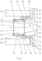
- Kokille zum kontinuierlichen Stranggiessen von Bolzen oder Barren mit darin homogen verteilten, primär erstarrten Festteilchen, die aus einzelnen degenerierten Dendriten bestehen, wobei die Kokille eine elektromagnetische Rühreinrichtung (80) aufweist,
die Kokille modular aufgebaut ist und der von ihr umschlossene Kokillenhohlraum (10) drei sequentiell angeordnete Kokillenzonen (60, 70, 52) mit einer gemeinsamen konzentrischen Kokillenlängsachse (m) aufweist, und jede der drei Kokillenzonen durch die Innenwandung (64, 74, 56) eines entsprechenden Kokillenelementes (62, 72, 54) begrenzt wird, wobei das erste Kokillenelement (62) eine Einleitöffnung (11) zum Einführen von Stranggussmaterial aufweist, und wenigstens die Innenwandung (64) des ersten Kokillenelementes (62) eine im Vergleich zum Stranggussmaterial niedrige Wärmeleitfähigkeit hat, das zweite Kokillenelement (72) Mittel zum Einleiten von Schmiermittel in den Kokillenhohlraum (10) aufweist, das dritte Kokillenelement (54) den formgebenden Kokillenbereich beschreibt, und wenigstens dessen Innenwandung (56) eine zum Stranggussmaterial vergleichbare Wärmeleitfähigkeit aufweist, das dritte Kokillenelement (54) wenigstens eine Kühlmittelkammer (22, 32) zur primären Kühlung von dessen Innenwandung (56), sowie Mittel (24) für eine sekundäre, gleichmässige Kühlmittelbeaufschlagung der Oberfläche des Bolzens oder Barrens nach dessen Austritt aus dem Kokillenhohlraum (10) aufweist, und die elektromagnetische Rühreinrichtung (80) dergestalt ist, dass dessen Rührwirkung wenigstens teilweise alle drei Kokillenzonen (60, 70, 52), sowie die gesamte Verfestigungszone des Stranggussmaterials umfasst, und die drei Kokillenelemente (62, 72, 54) dergestalt ausgebildet sind, dass die der zweiten Kokillenzone (70) anliegenden Querschnittsflächen der ersten und dritten Kokillenzonen (60, 52) kleiner sind als jede beliebige Querschnittsfläche der zweiten Kokillenzone (70), und die der zweiten Kokillenzone (70) anliegende Querschnittsfläche der dritten Kokillenzone (52) grösser ist als die der zweiten Kokillenzone (70) anliegende Querschnittsfläche der ersten Kokillenzone (60). - Kokille nach Anspruch 1, dadurch gekennzeichnet, dass der Querschnitt der Innenwandung (64) des ersten Kokillenelementes (62) auf der zur zweiten Kokillenzone (70) anliegenden Seite grösser ist als der Querschnitt der Einleitöffnung (11).
- Kokille nach Anspruch 2, dadurch gekennzeichnet, dass die Innenwandung (64) des ersten Kokillenelementes (62), ausgehend von dem zur zweiten Kokillenzone (70) anliegenden Querschnitt, einen gegen die Einleitöffnung (11) hin sich kontinuierlich verjüngenden Querschnitt aufweist.
- Kokille nach einem der Ansprüche 1 bis 3, dadurch gekennzeichnet, dass das erste Kokillenelement (62) aus Keramik besteht, wobei bevorzugt zumindest dessen Innenwandung (64) im wesentlichen porenfrei ist.
- Kokille nach einem der Ansprüche 1 bis 4, dadurch gekennzeichnet, dass das zweite Kokillenelement (72) einen ringförmigen Körper aus hochporösem, temperaturbeständigem Material enthält oder daraus besteht, wobei die Porosität dergestalt ist, dass Schmiermittel durch das poröse Material hindurchdiffundieren kann.
- Kokille nach Anspruch 5, dadurch gekennzeichnet, dass der ringförmige Körper aus Graphit oder Keramik besteht.
- Kokille nach einem der Ansprüche 1 bis 4, dadurch gekennzeichnet, dass das zweite Kokillenelement (72) einen ringförmigen Körper aus flaumigem, filzartigem oder schwammartigem Material enthält oder aus einem derartigen ringförmigen Körper besteht.
- Kokille nach Anspruch 7, dadurch gekennzeichnet, dass der ringförmige Körper des zweiten Kokillenelementes (72) aus chemisch stabilen, unbrennbaren Mineralfasern, enthaltend bis zu 62.3 Gew.-% Al2O3 und bis zu 37.2 Gew.-% SiO2, besteht.
- Kokille nach einem der Ansprüche 1 bis 8, dadurch gekennzeichnet, dass die im dritten Kokillenelement (54) enthaltenen Mittel (24) für die sekundäre, gleichmässige Kühlmittelbeaufscblagung der Oberfläche des Bolzens oder Barrens nach dessen Austritt aus dem Kokillenhohlraum (10) vorzugsweise aus einer Vielzahl von Sekundär-Kühlmittelkanälen (24) bestehen, die einerseits mit der Kühlmittelkammer (32) in Verbindung stehen und andererseits schräg auf die Oberfläche des aus der Kokille austretenden Bolzens oder Barrens gerichtet sind.
- Kokille nach einem der Ansprüche 1 bis 9, dadurch gekennzeichnet, dass die Kokille Befestigungselemente (84, 86) zur Halterung der Kokillenelemente (54, 62, 72) aufweist, welche eine Kühlmittelzuführung (87) für die Zufuhr von Kühlmittel in das dritte Kokillenelement (54) enthalten, wobei die Kühlmittelzuführung (87) in einem zur Einleitöffnung (11) fernen Bereich einen im wesentlichen parallel zur Kokillenlängsachse (m) verlaufenden Teil (88) und in einem zur Einleitöffnung (11) nahen Bereich einen radial nach aussen verlaufenden Teil (90) aufweist, und der radial nach aussen verlaufende Teil (90) bezüglich der elektromagnetischen Rühreinrichtung (80) gegen die Einleitöffnung (11) hin versetzt angeordnet ist.
- Kokille nach einem der Ansprüche 1 bis 10, dadurch gekennzeichnet, dass das dritte Kokillenelement (54) an seiner Kontaktfläche mit dem zweiten Kokillenelement (72) eine bezüglich der Kokillenlängsachse (m) konzentrische, ringnutförmige Ausnehmung, den Schmiermittelaustrittsring (41), für die Zufuhr von Schmiermittel in das zweite Kokillenelement (72), sowie Mittel (40, 42, 43) für die Zufuhr von Schmiermittel in den Schmiermittelaustrittsring (41) aufweist.
- Kokille nach Anspruch 11, dadurch gekennzeichnet dass die Kokille Befestigungselemente (84, 86) zur Halterung der Kokillenelemente (54, 62, 72) aufweist, welche wenigstens eine Schmiermittelzuführung (91) für die Zufuhr von Schmiermittel in das dritte Kokillenelement (54) enthalten, wobei die Schmiermittelzuführung (91) in einem zur Einleitöffnung (11) fernen Bereich einen im wesentlichen parallel zur Kokillenlängsachse (m) verlaufenden Teil (92) und in einem zur Einleitöffnung (11) nahen Bereich einen radial nach aussen verlaufenden Teil (94) aufweist, und der radial nach aussen verlaufende Teil (94) bezüglich der elektromagnetischen Rühreinrichtung (80) gegen die Einleitöffnung (11) hin versetzt angeordnet ist.
- Kokille nach einem der Ansprüche 1 bis 12, dadurch gekennzeichnet, dass das dritte Kokillenelement aus einer Innenhülse (30) und einem Tragkörper (20) besteht, wobei die Innenhülse (30) und der Tragkörper (20) eine gemeinsame konzentrische Längsachse aufweisen, welche mit der Kokillenlängsachse (m) zusammenfällt, und die Innenhülse (30) bezüglich der Kokillenlängsachse (m) innen liegt und die dritte Kokillenzone (52) seitlich begrenzt, und der Tragkörper (20) bezüglich der Kokillenlängsachse (m) aussen liegt und die Innenhülse (30) aufnimmt, wobei die Inenhülse (30) und der Tragkörper (20) lösbar miteinander durch Einschieben der Innenhülse (30) in den Tragkörper (20) verbunden sind, und die Innenhülse (30) auf der dem Tragkörper (20) zugewandten Seite und/oder der Tragkörper (20) auf der der Innenhülse (30) zugewandten Seite derart beschaffen sind, dass durch das Einschieben der Innenhülse (30) in den Tragkörper (20) eine bezüglich der Kokillenlängsachse (m) konzentrische, ringförmige Kühlmittelkammer (32) für die Aufnahme von Kühlmittel entsteht.
- Kokille nach einem der Ansprüche 1 bis 13, dadurch gekennzeichnet dass die Innenwandung (56) des dritten Kokillenelementes (54) an ihrer Oberfläche (46) Schmiermittel-Führungsmittel (50), die bevorzugt parallel zur Kokillenlängsachse (m) verlaufen, aufweist.
- Kokille nach Anspruch 14, dadurch gekennzeichnet, dass die Schmiermittel-Führungsmittel (50) parallel zur Kokillenachse (m) verlaufende Rillen (50) darstellen, die zuflussseitig erst nach einer Strecke von 1/4 bis 1/3 der Länge der dritten Kokillenzone (52) beginnen und sich bevorzugt bezüglich ihrer Rillentiefe und Rillenbreite in Richtung der Austrittöffnung (14) der dritten Kokillenzone (52) konisch erweitern.
- Verwendung der Kokille gemäss wenigstens einem der Ansprüche 1 bis 15 zum kontinuierlichen horizontalen Stranggiessen von Bolzen oder Barren mit darin homogen verteilten, primär erstarrten Festteilchen, die aus einzelnen degenerierten Dendriten bestehen.
- Verfahren zur kontinuierlichen Herstellung von Bolzen oder Barren mit thixotropen Eigenschaften bei deren Weiterverarbeitung durch Stranggiessen von Stranggussmaterial mit einer Kokille nach einem der Ansprüche 1 bis 15,
wobei
Stranggussmaterial in die Einleitöffnung (11) des ersten Kokillenelementes (62) eingeleitet und nacheinander durch die erste (60), zweite (70) und dritte (52) Kokillenzone geführt wird, und die elektromagnetische Rühreinrichtung (80) ein um die Kokillenlängsachse (m) rotierendes Magnetfeld in der Weise erzeugt, dass das Stranggussmaterial einerseits im zur Einleitöffnung (11) nahen Bereich der ersten Kokillenzone (60) keine Rührwirkung erfährt, andererseits wenigstens im zur zweiten Kokillenzone (70) nahen Bereich der ersten Kokillenzone (60), und in den zweiten (70) und dritten (52) Kokillenzonen, sowie in der gesamten Verfestigungszone des Stranggussmaterials kräftig gerührt wird, so dass bei der Erstarrung sich bildende Dendriten abgeschert werden, und die gesamte Innenfläche (46) des dritten Kokillenelementes (54) kontinuierlich geschmiert wird, das Stranggussmaterial an der Innenwandung (56) des dritten Kokillenelementes (54) einer primären Kühlung unterworfen wird, so dass der aus der Kokille austretende Bolzen oder Barren wenigstens in seiner äusseren Randzone in fester Form vorliegt, und der Bolzen oder Barren nach dessen Austritt aus der Kokille durch eine sekundäre Kühlung mittels Kühlmittelbeaufschlagung weiter gekühlt wird. - Verfahren nach Anspruch 17, dadurch gekennzeichnet, dass das Rühren mittels einem Stator eines mehrpoligen, beispielsweise zwei-, vier-, oder insbesondere sechspoligen Induktionsmotors geschieht.
Priority Applications (6)
| Application Number | Priority Date | Filing Date | Title |
|---|---|---|---|
| DE59603003T DE59603003D1 (de) | 1996-06-06 | 1996-06-06 | Stranggusskokille |
| EP96810369A EP0811446B1 (de) | 1996-06-06 | 1996-06-06 | Stranggusskokille |
| AT96810369T ATE184225T1 (de) | 1996-06-06 | 1996-06-06 | Stranggusskokille |
| ES96810369T ES2136962T3 (es) | 1996-06-06 | 1996-06-06 | Coquilla para colada continua. |
| NO972423A NO972423L (no) | 1996-06-06 | 1997-05-28 | Strengstöpekokille |
| IS4493A IS4493A (is) | 1996-06-06 | 1997-06-02 | Mót til að steypa hleifa |
Applications Claiming Priority (1)
| Application Number | Priority Date | Filing Date | Title |
|---|---|---|---|
| EP96810369A EP0811446B1 (de) | 1996-06-06 | 1996-06-06 | Stranggusskokille |
Publications (2)
| Publication Number | Publication Date |
|---|---|
| EP0811446A1 EP0811446A1 (de) | 1997-12-10 |
| EP0811446B1 true EP0811446B1 (de) | 1999-09-08 |
Family
ID=8225624
Family Applications (1)
| Application Number | Title | Priority Date | Filing Date |
|---|---|---|---|
| EP96810369A Expired - Lifetime EP0811446B1 (de) | 1996-06-06 | 1996-06-06 | Stranggusskokille |
Country Status (6)
| Country | Link |
|---|---|
| EP (1) | EP0811446B1 (de) |
| AT (1) | ATE184225T1 (de) |
| DE (1) | DE59603003D1 (de) |
| ES (1) | ES2136962T3 (de) |
| IS (1) | IS4493A (de) |
| NO (1) | NO972423L (de) |
Cited By (1)
| Publication number | Priority date | Publication date | Assignee | Title |
|---|---|---|---|---|
| WO2026044315A1 (de) | 2024-08-28 | 2026-03-05 | Hpi "High Performance Industrietechnik" Gmbh | Giessformring |
Families Citing this family (5)
| Publication number | Priority date | Publication date | Assignee | Title |
|---|---|---|---|---|
| CN113798451B (zh) * | 2021-09-08 | 2023-01-10 | 宁波金田铜业(集团)股份有限公司 | 一种铜合金水平连铸结晶器 |
| CN114309504B (zh) * | 2021-12-28 | 2023-07-11 | 东北轻合金有限责任公司 | 一种变形铝合金空心锭热顶铸造结晶器 |
| CN114406214A (zh) * | 2022-01-18 | 2022-04-29 | 江西理工大学 | 一种分段式水平连铸结晶器 |
| CN115475920A (zh) * | 2022-09-27 | 2022-12-16 | 铜陵有色金属集团股份有限公司金威铜业分公司 | 一种促进结晶器内部铸坯快速成型的结晶器及使用方法 |
| CN120394799B (zh) * | 2025-05-15 | 2025-10-17 | 南通海门鑫瑞船舶配件有限公司 | 一种有色金属合金生产用连铸炉 |
Family Cites Families (6)
| Publication number | Priority date | Publication date | Assignee | Title |
|---|---|---|---|---|
| US4450893A (en) * | 1981-04-27 | 1984-05-29 | International Telephone And Telegraph Corporation | Method and apparatus for casting metals and alloys |
| US4597432A (en) * | 1981-04-29 | 1986-07-01 | Wagstaff Engineering, Inc. | Molding device |
| GB2129344B (en) * | 1982-10-20 | 1986-11-19 | Wagstaff Engineering Inc | Direct chill casting |
| DE3424457A1 (de) * | 1984-07-03 | 1986-01-16 | Kaiser Aluminium Europe Inc., 4000 Düsseldorf | Vorrichtung zum stranggiessen von metallen |
| US4726944A (en) * | 1986-05-28 | 1988-02-23 | Osipow Lloyd I | Instant lathering shampoo |
| IT1231824B (it) * | 1989-09-05 | 1992-01-14 | Aluminia Spa | Apparecchiatura per la colata semicontinua in acque delle leghe leggere, strutturata in modo da eliminare rischi di esplosione. |
-
1996
- 1996-06-06 AT AT96810369T patent/ATE184225T1/de not_active IP Right Cessation
- 1996-06-06 EP EP96810369A patent/EP0811446B1/de not_active Expired - Lifetime
- 1996-06-06 DE DE59603003T patent/DE59603003D1/de not_active Expired - Fee Related
- 1996-06-06 ES ES96810369T patent/ES2136962T3/es not_active Expired - Lifetime
-
1997
- 1997-05-28 NO NO972423A patent/NO972423L/no not_active Application Discontinuation
- 1997-06-02 IS IS4493A patent/IS4493A/is unknown
Cited By (1)
| Publication number | Priority date | Publication date | Assignee | Title |
|---|---|---|---|---|
| WO2026044315A1 (de) | 2024-08-28 | 2026-03-05 | Hpi "High Performance Industrietechnik" Gmbh | Giessformring |
Also Published As
| Publication number | Publication date |
|---|---|
| IS4493A (is) | 1997-12-07 |
| EP0811446A1 (de) | 1997-12-10 |
| NO972423L (no) | 1997-12-08 |
| ATE184225T1 (de) | 1999-09-15 |
| ES2136962T3 (es) | 1999-12-01 |
| NO972423D0 (no) | 1997-05-28 |
| DE59603003D1 (de) | 1999-10-14 |
Similar Documents
| Publication | Publication Date | Title |
|---|---|---|
| EP0718059B1 (de) | Oxidabstreifer | |
| DE69814023T2 (de) | Schreckplatten-Entlüftungsventil für Druckgiessformen | |
| EP0935504B1 (de) | Verfahren zur herstellung eines metallprofilstranges | |
| DE60107690T2 (de) | Verfahren und vorrichtung zur herstellung von metall-legierungs-gussteilen | |
| DE69125753T2 (de) | Formen von kompositen Materialien | |
| DE60128114T2 (de) | Druckgiessen von aluminium | |
| DE2401145A1 (de) | Verfahren und vorrichtung zum kontinuierlichen giessen | |
| DE60133466T2 (de) | Metallischer einsatzkörper, verfahren zur herstellung desselben und metallisches gussteil | |
| DE60036646T2 (de) | Giesssysteme und verfahren mit hilfskühlung der flüssigen oberfläche der giesskörper | |
| DE69110532T2 (de) | Verfahren und diesbezügliche Vorrichtung für indirektes Giessen von Knüppeln aus metallischen Legierungen im halbflüssigen oder pastösen Zustand. | |
| EP0811446A1 (de) | Stranggusskokille | |
| EP1499462A1 (de) | Anpassung des wärmeüberganges bei stranggiesskokillen, insbesondere im giessspiegelbereich | |
| WO2000006323A1 (de) | Eingusssystem für das thixoformen | |
| DE69029467T2 (de) | Stranggussform und Stranggussverfahren | |
| EP0733420B1 (de) | Modular aufgebaute Stranggiesskokille | |
| DE2930572A1 (de) | Selbstschmierende stranggiesskokille | |
| DE846900C (de) | Giessform fuer das stetige Giessen von Metallen | |
| EP0158898B1 (de) | Stranggiessvorrichtung und Verfahren zu deren Herstellung | |
| DE4103963A1 (de) | Verfahren zum kontinuierlichen stranggiessen von kupferlegierungen | |
| DE19918229C2 (de) | Verfahren zum Herstellen von Rohlingen für Zylinderlaufbüchsen | |
| DE4006842A1 (de) | Bandgiessanlage mit oszillierender durchlaufkokille | |
| DE2406252C3 (de) | Verfahren und Vorrichtung zum Stranggießen und Weiterverarbeiten des gegossenen Strangs | |
| EP3406368A1 (de) | Kokille zum stranggiessen von metallischen produkten | |
| DE19918231C2 (de) | Verfahren zum Herstellen von Rohlingen für Zylinderlaufbüchsen | |
| DE19710887C2 (de) | Verwendung einer Kokille zum Herstellen von Barren aus Leichtmetall oder einer Leichtmetallegierung, insbesondere aus Magnesium oder einer Magnesiumlegierung |
Legal Events
| Date | Code | Title | Description |
|---|---|---|---|
| PUAI | Public reference made under article 153(3) epc to a published international application that has entered the european phase |
Free format text: ORIGINAL CODE: 0009012 |
|
| AK | Designated contracting states |
Kind code of ref document: A1 Designated state(s): AT BE CH DE ES FR GB IT LI NL SE |
|
| 17P | Request for examination filed |
Effective date: 19980610 |
|
| 17Q | First examination report despatched |
Effective date: 19980714 |
|
| GRAG | Despatch of communication of intention to grant |
Free format text: ORIGINAL CODE: EPIDOS AGRA |
|
| GRAG | Despatch of communication of intention to grant |
Free format text: ORIGINAL CODE: EPIDOS AGRA |
|
| GRAH | Despatch of communication of intention to grant a patent |
Free format text: ORIGINAL CODE: EPIDOS IGRA |
|
| GRAH | Despatch of communication of intention to grant a patent |
Free format text: ORIGINAL CODE: EPIDOS IGRA |
|
| GRAA | (expected) grant |
Free format text: ORIGINAL CODE: 0009210 |
|
| AK | Designated contracting states |
Kind code of ref document: B1 Designated state(s): AT BE CH DE ES FR GB IT LI NL SE |
|
| REF | Corresponds to: |
Ref document number: 184225 Country of ref document: AT Date of ref document: 19990915 Kind code of ref document: T |
|
| REG | Reference to a national code |
Ref country code: CH Ref legal event code: EP |
|
| GBT | Gb: translation of ep patent filed (gb section 77(6)(a)/1977) |
Effective date: 19990910 |
|
| REF | Corresponds to: |
Ref document number: 59603003 Country of ref document: DE Date of ref document: 19991014 |
|
| REG | Reference to a national code |
Ref country code: ES Ref legal event code: FG2A Ref document number: 2136962 Country of ref document: ES Kind code of ref document: T3 |
|
| ET | Fr: translation filed | ||
| PGFP | Annual fee paid to national office [announced via postgrant information from national office to epo] |
Ref country code: GB Payment date: 20000522 Year of fee payment: 5 |
|
| PGFP | Annual fee paid to national office [announced via postgrant information from national office to epo] |
Ref country code: ES Payment date: 20000612 Year of fee payment: 5 |
|
| PGFP | Annual fee paid to national office [announced via postgrant information from national office to epo] |
Ref country code: FR Payment date: 20000615 Year of fee payment: 5 |
|
| PGFP | Annual fee paid to national office [announced via postgrant information from national office to epo] |
Ref country code: NL Payment date: 20000619 Year of fee payment: 5 Ref country code: BE Payment date: 20000619 Year of fee payment: 5 Ref country code: AT Payment date: 20000619 Year of fee payment: 5 |
|
| PGFP | Annual fee paid to national office [announced via postgrant information from national office to epo] |
Ref country code: SE Payment date: 20000621 Year of fee payment: 5 |
|
| PGFP | Annual fee paid to national office [announced via postgrant information from national office to epo] |
Ref country code: DE Payment date: 20000704 Year of fee payment: 5 |
|
| PGFP | Annual fee paid to national office [announced via postgrant information from national office to epo] |
Ref country code: CH Payment date: 20000705 Year of fee payment: 5 |
|
| PLBE | No opposition filed within time limit |
Free format text: ORIGINAL CODE: 0009261 |
|
| STAA | Information on the status of an ep patent application or granted ep patent |
Free format text: STATUS: NO OPPOSITION FILED WITHIN TIME LIMIT |
|
| 26N | No opposition filed | ||
| PG25 | Lapsed in a contracting state [announced via postgrant information from national office to epo] |
Ref country code: GB Free format text: LAPSE BECAUSE OF NON-PAYMENT OF DUE FEES Effective date: 20010606 Ref country code: AT Free format text: LAPSE BECAUSE OF NON-PAYMENT OF DUE FEES Effective date: 20010606 |
|
| PG25 | Lapsed in a contracting state [announced via postgrant information from national office to epo] |
Ref country code: SE Free format text: LAPSE BECAUSE OF NON-PAYMENT OF DUE FEES Effective date: 20010607 Ref country code: ES Free format text: LAPSE BECAUSE OF NON-PAYMENT OF DUE FEES Effective date: 20010607 |
|
| PG25 | Lapsed in a contracting state [announced via postgrant information from national office to epo] |
Ref country code: LI Free format text: LAPSE BECAUSE OF NON-PAYMENT OF DUE FEES Effective date: 20010630 Ref country code: CH Free format text: LAPSE BECAUSE OF NON-PAYMENT OF DUE FEES Effective date: 20010630 Ref country code: BE Free format text: LAPSE BECAUSE OF NON-PAYMENT OF DUE FEES Effective date: 20010630 |
|
| BERE | Be: lapsed |
Owner name: ALUSUISSE TECHNOLOGY & MANAGEMENT A.G. Effective date: 20010630 |
|
| PG25 | Lapsed in a contracting state [announced via postgrant information from national office to epo] |
Ref country code: NL Free format text: LAPSE BECAUSE OF NON-PAYMENT OF DUE FEES Effective date: 20020101 |
|
| GBPC | Gb: european patent ceased through non-payment of renewal fee |
Effective date: 20010606 |
|
| EUG | Se: european patent has lapsed |
Ref document number: 96810369.7 |
|
| REG | Reference to a national code |
Ref country code: CH Ref legal event code: PL |
|
| PG25 | Lapsed in a contracting state [announced via postgrant information from national office to epo] |
Ref country code: FR Free format text: LAPSE BECAUSE OF NON-PAYMENT OF DUE FEES Effective date: 20020228 |
|
| NLV4 | Nl: lapsed or anulled due to non-payment of the annual fee |
Effective date: 20020101 |
|
| PG25 | Lapsed in a contracting state [announced via postgrant information from national office to epo] |
Ref country code: DE Free format text: LAPSE BECAUSE OF NON-PAYMENT OF DUE FEES Effective date: 20020403 |
|
| REG | Reference to a national code |
Ref country code: ES Ref legal event code: FD2A Effective date: 20020203 |
|
| PG25 | Lapsed in a contracting state [announced via postgrant information from national office to epo] |
Ref country code: IT Free format text: LAPSE BECAUSE OF NON-PAYMENT OF DUE FEES;WARNING: LAPSES OF ITALIAN PATENTS WITH EFFECTIVE DATE BEFORE 2007 MAY HAVE OCCURRED AT ANY TIME BEFORE 2007. THE CORRECT EFFECTIVE DATE MAY BE DIFFERENT FROM THE ONE RECORDED. Effective date: 20050606 |