EP0810832B1 - Träger von büstenhaltern - Google Patents
Träger von büstenhaltern Download PDFInfo
- Publication number
- EP0810832B1 EP0810832B1 EP96900529A EP96900529A EP0810832B1 EP 0810832 B1 EP0810832 B1 EP 0810832B1 EP 96900529 A EP96900529 A EP 96900529A EP 96900529 A EP96900529 A EP 96900529A EP 0810832 B1 EP0810832 B1 EP 0810832B1
- Authority
- EP
- European Patent Office
- Prior art keywords
- strap
- reinforcing insert
- insert
- carrier
- stiffening insert
- Prior art date
- Legal status (The legal status is an assumption and is not a legal conclusion. Google has not performed a legal analysis and makes no representation as to the accuracy of the status listed.)
- Expired - Lifetime
Links
- 239000000463 material Substances 0.000 claims description 31
- 230000003014 reinforcing effect Effects 0.000 claims description 20
- 230000001681 protective effect Effects 0.000 claims description 19
- 229920003023 plastic Polymers 0.000 claims description 8
- 239000004033 plastic Substances 0.000 claims description 8
- 239000006260 foam Substances 0.000 claims description 6
- 239000012815 thermoplastic material Substances 0.000 claims description 5
- 239000007789 gas Substances 0.000 claims description 4
- 239000007788 liquid Substances 0.000 claims description 4
- 239000000499 gel Substances 0.000 claims description 3
- 230000002787 reinforcement Effects 0.000 claims description 3
- 239000007799 cork Substances 0.000 claims description 2
- 229920001971 elastomer Polymers 0.000 claims description 2
- 239000004816 latex Substances 0.000 claims description 2
- 229920000126 latex Polymers 0.000 claims description 2
- 239000010985 leather Substances 0.000 claims description 2
- 239000005060 rubber Substances 0.000 claims description 2
- 239000002023 wood Substances 0.000 claims description 2
- 239000002184 metal Substances 0.000 claims 1
- 238000005452 bending Methods 0.000 description 12
- -1 polyethylene Polymers 0.000 description 8
- 238000004026 adhesive bonding Methods 0.000 description 7
- 238000003466 welding Methods 0.000 description 6
- 230000008901 benefit Effects 0.000 description 5
- 239000004743 Polypropylene Substances 0.000 description 4
- 210000000481 breast Anatomy 0.000 description 4
- 238000011049 filling Methods 0.000 description 4
- 229920001155 polypropylene Polymers 0.000 description 4
- 239000004814 polyurethane Substances 0.000 description 4
- 238000003825 pressing Methods 0.000 description 4
- 229920000742 Cotton Polymers 0.000 description 3
- PEDCQBHIVMGVHV-UHFFFAOYSA-N Glycerine Chemical compound OCC(O)CO PEDCQBHIVMGVHV-UHFFFAOYSA-N 0.000 description 3
- 239000004698 Polyethylene Substances 0.000 description 3
- 229920002301 cellulose acetate Polymers 0.000 description 3
- 238000013461 design Methods 0.000 description 3
- 238000004519 manufacturing process Methods 0.000 description 3
- 238000000034 method Methods 0.000 description 3
- 238000000465 moulding Methods 0.000 description 3
- 229920000573 polyethylene Polymers 0.000 description 3
- 229920000139 polyethylene terephthalate Polymers 0.000 description 3
- 239000005020 polyethylene terephthalate Substances 0.000 description 3
- 238000009958 sewing Methods 0.000 description 3
- 230000007704 transition Effects 0.000 description 3
- CURLTUGMZLYLDI-UHFFFAOYSA-N Carbon dioxide Chemical compound O=C=O CURLTUGMZLYLDI-UHFFFAOYSA-N 0.000 description 2
- 229920000877 Melamine resin Polymers 0.000 description 2
- 239000004952 Polyamide Substances 0.000 description 2
- 238000005266 casting Methods 0.000 description 2
- 239000011248 coating agent Substances 0.000 description 2
- 238000000576 coating method Methods 0.000 description 2
- 238000007598 dipping method Methods 0.000 description 2
- IVJISJACKSSFGE-UHFFFAOYSA-N formaldehyde;1,3,5-triazine-2,4,6-triamine Chemical compound O=C.NC1=NC(N)=NC(N)=N1 IVJISJACKSSFGE-UHFFFAOYSA-N 0.000 description 2
- SLGWESQGEUXWJQ-UHFFFAOYSA-N formaldehyde;phenol Chemical compound O=C.OC1=CC=CC=C1 SLGWESQGEUXWJQ-UHFFFAOYSA-N 0.000 description 2
- 230000002427 irreversible effect Effects 0.000 description 2
- 238000003475 lamination Methods 0.000 description 2
- 229920001684 low density polyethylene Polymers 0.000 description 2
- 239000004702 low-density polyethylene Substances 0.000 description 2
- 229920001568 phenolic resin Polymers 0.000 description 2
- 229920003229 poly(methyl methacrylate) Polymers 0.000 description 2
- 229920002647 polyamide Polymers 0.000 description 2
- 229920001707 polybutylene terephthalate Polymers 0.000 description 2
- 229920000515 polycarbonate Polymers 0.000 description 2
- 239000004417 polycarbonate Substances 0.000 description 2
- 239000004926 polymethyl methacrylate Substances 0.000 description 2
- 229920006324 polyoxymethylene Polymers 0.000 description 2
- 229920001296 polysiloxane Polymers 0.000 description 2
- 229920002635 polyurethane Polymers 0.000 description 2
- 239000004800 polyvinyl chloride Substances 0.000 description 2
- 230000002441 reversible effect Effects 0.000 description 2
- 239000002002 slurry Substances 0.000 description 2
- 238000005507 spraying Methods 0.000 description 2
- 239000003351 stiffener Substances 0.000 description 2
- 229920002994 synthetic fiber Polymers 0.000 description 2
- 239000004758 synthetic textile Substances 0.000 description 2
- 238000009864 tensile test Methods 0.000 description 2
- 229920001187 thermosetting polymer Polymers 0.000 description 2
- 238000005406 washing Methods 0.000 description 2
- 229920001817 Agar Polymers 0.000 description 1
- UGFAIRIUMAVXCW-UHFFFAOYSA-N Carbon monoxide Chemical compound [O+]#[C-] UGFAIRIUMAVXCW-UHFFFAOYSA-N 0.000 description 1
- LFQSCWFLJHTTHZ-UHFFFAOYSA-N Ethanol Chemical compound CCO LFQSCWFLJHTTHZ-UHFFFAOYSA-N 0.000 description 1
- 229930182556 Polyacetal Natural products 0.000 description 1
- 239000004793 Polystyrene Substances 0.000 description 1
- VYPSYNLAJGMNEJ-UHFFFAOYSA-N Silicium dioxide Chemical compound O=[Si]=O VYPSYNLAJGMNEJ-UHFFFAOYSA-N 0.000 description 1
- 229920002472 Starch Polymers 0.000 description 1
- 239000002174 Styrene-butadiene Substances 0.000 description 1
- 239000004676 acrylonitrile butadiene styrene Substances 0.000 description 1
- 230000006978 adaptation Effects 0.000 description 1
- 230000002411 adverse Effects 0.000 description 1
- 239000008272 agar Substances 0.000 description 1
- MTAZNLWOLGHBHU-UHFFFAOYSA-N butadiene-styrene rubber Chemical compound C=CC=C.C=CC1=CC=CC=C1 MTAZNLWOLGHBHU-UHFFFAOYSA-N 0.000 description 1
- 238000003490 calendering Methods 0.000 description 1
- 229910002092 carbon dioxide Inorganic materials 0.000 description 1
- 239000001569 carbon dioxide Substances 0.000 description 1
- 229910002091 carbon monoxide Inorganic materials 0.000 description 1
- 229920002678 cellulose Polymers 0.000 description 1
- 239000001913 cellulose Substances 0.000 description 1
- 239000003795 chemical substances by application Substances 0.000 description 1
- 239000012459 cleaning agent Substances 0.000 description 1
- 150000001875 compounds Chemical class 0.000 description 1
- 238000010411 cooking Methods 0.000 description 1
- 238000004132 cross linking Methods 0.000 description 1
- 239000003599 detergent Substances 0.000 description 1
- 238000009826 distribution Methods 0.000 description 1
- 230000000694 effects Effects 0.000 description 1
- 239000013013 elastic material Substances 0.000 description 1
- 238000005516 engineering process Methods 0.000 description 1
- 238000001125 extrusion Methods 0.000 description 1
- 238000010101 extrusion blow moulding Methods 0.000 description 1
- 239000000835 fiber Substances 0.000 description 1
- 239000012530 fluid Substances 0.000 description 1
- 238000005187 foaming Methods 0.000 description 1
- 238000010438 heat treatment Methods 0.000 description 1
- 229920001903 high density polyethylene Polymers 0.000 description 1
- 239000004700 high-density polyethylene Substances 0.000 description 1
- 201000010759 hypertrophy of breast Diseases 0.000 description 1
- 230000002757 inflammatory effect Effects 0.000 description 1
- 238000002347 injection Methods 0.000 description 1
- 239000007924 injection Substances 0.000 description 1
- 238000010102 injection blow moulding Methods 0.000 description 1
- 238000001746 injection moulding Methods 0.000 description 1
- 239000010954 inorganic particle Substances 0.000 description 1
- 238000003780 insertion Methods 0.000 description 1
- 230000037431 insertion Effects 0.000 description 1
- 238000010409 ironing Methods 0.000 description 1
- 230000007794 irritation Effects 0.000 description 1
- 238000011068 loading method Methods 0.000 description 1
- 230000007774 longterm Effects 0.000 description 1
- 230000001926 lymphatic effect Effects 0.000 description 1
- 239000000203 mixture Substances 0.000 description 1
- 229910052756 noble gas Inorganic materials 0.000 description 1
- 150000002835 noble gases Chemical class 0.000 description 1
- 230000003287 optical effect Effects 0.000 description 1
- 239000011146 organic particle Substances 0.000 description 1
- 238000010422 painting Methods 0.000 description 1
- 229920002223 polystyrene Polymers 0.000 description 1
- 239000011148 porous material Substances 0.000 description 1
- 238000003672 processing method Methods 0.000 description 1
- 229920005989 resin Polymers 0.000 description 1
- 239000011347 resin Substances 0.000 description 1
- 238000007789 sealing Methods 0.000 description 1
- 239000000741 silica gel Substances 0.000 description 1
- 229910002027 silica gel Inorganic materials 0.000 description 1
- 238000005245 sintering Methods 0.000 description 1
- 239000007787 solid Substances 0.000 description 1
- 238000009987 spinning Methods 0.000 description 1
- 239000008107 starch Substances 0.000 description 1
- 235000019698 starch Nutrition 0.000 description 1
- 239000011145 styrene acrylonitrile resin Substances 0.000 description 1
- 239000011115 styrene butadiene Substances 0.000 description 1
- 229920003048 styrene butadiene rubber Polymers 0.000 description 1
- 230000008961 swelling Effects 0.000 description 1
- 238000012360 testing method Methods 0.000 description 1
- 239000004753 textile Substances 0.000 description 1
- 238000003856 thermoforming Methods 0.000 description 1
- 229920001169 thermoplastic Polymers 0.000 description 1
- 239000004416 thermosoftening plastic Substances 0.000 description 1
- 229920006337 unsaturated polyester resin Polymers 0.000 description 1
- XLYOFNOQVPJJNP-UHFFFAOYSA-N water Substances O XLYOFNOQVPJJNP-UHFFFAOYSA-N 0.000 description 1
- 238000004804 winding Methods 0.000 description 1
Images



Classifications
-
- A—HUMAN NECESSITIES
- A41—WEARING APPAREL
- A41C—CORSETS; BRASSIERES
- A41C3/00—Brassieres
- A41C3/12—Component parts
-
- A—HUMAN NECESSITIES
- A41—WEARING APPAREL
- A41F—GARMENT FASTENINGS; SUSPENDERS
- A41F15/00—Shoulder or like straps
Definitions
- the present invention relates to a bra of bras with an interchangeable reinforcement insert the features specified in claim 1.
- US-A 4100924 relates to a bra for bras 2 diagonally running, parallelogram-shaped Stiffening inserts in pocket-shaped rooms, which are characterized by numerous Stitches are irreversibly connected to the carrier.
- FR-A 814367 describes a shoulder strap on the Bottom of a stiffening insert by sewing and bonding is irreversible and rigid.
- WO-91/0495 discloses a solid backpack shoulder strap with transverse notches. This backpack shoulder strap however, does not include a stiffening insert.
- FR-A 973 507 discloses a tubular, flattened bra straps with a buttonhole to insert a stiffening insert into the inside of a pocket of the Carrier by means of a slot-shaped opening in the carrier.
- the longitudinal axis the buttonhole runs parallel to the longitudinal axis of the wearer.
- a carrier according to this document has the one Disadvantage that the stiffening insert unintentionally can be easily moved along the longitudinal axis of the beam can.
- the stiffening insert moves out of the Crown area of the wearer, this is what happens According to the invention to be avoided straight bending side carrier edges up.
- the rolled up one The wearer then painfully cuts into the shoulder area on.
- the institution in accordance with this citation also has the Disadvantage that it is when performing the stiffening insert through the narrow buttonhole, whose longitudinal axis also is aligned parallel to the longitudinal axis of the carrier, to a significant material stress on the wearer in Buttonhole area or the stiffening insert itself comes.
- the objective object of the invention over this The closest prior art is therefore in Providing a straps for bras with interchangeable stiffening insert, which one unintentional moving of the stiffening insert excludes while wearing and even with a long one Has excellent lateral stability and maintains, does not know the problem of chafing through removing and inserting the stiffening insert no optical or functional loss, whose Stiffening insert when inserting or removing no wear and tear to the wearer Bending stresses is subjected to and which a long Has lifespan.
- this object is achieved with a generic Bra of bras by in the claim 1 specified features solved.
- One according to the invention with an integrated stiffening insert configured bra of bras has in particular the advantage of being extremely stable in the long term, wide contact area in the shoulder area. As a result, the dead weight is also above average large breasts while maintaining a low wing loading evenly distributed on the shoulder. To this The straps are cut into the shoulder area avoided and the problems outlined above occur not on.
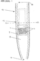
- Figure 1 shows a top view of an inventive Bra wearing bra.
- it comprises an elongated, strip-shaped Carrier underside (5), an elongated, strip-shaped Carrier top (9) and at least a little on the width the superimposed, strip-shaped top and Adjusted plate-shaped stiffening insert on the underside (1), which at least in the area of the vertex (15) of the Carrier (13) comes to rest.
- the strip-shaped upper and lower sides of the carrier (9, 5) usually consist of natural or synthetic Textile material and are in their lateral edge areas lengthwise with each other, for example through a seam or bonding.
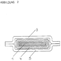
- the stiffening insert (1) is located essentially integrates itself into one formed at least from the upper and lower side of the carrier (9, 5) tubular straps (13) for bras (see also Figure 2).
- the stiffening insert (1) comprises a central area, which is essentially plate-shaped and square or is rectangular. To adapt to the carrier shape can look at in the longitudinal direction of the carrier (13) front and rear ends (18) of the stiffening insert rejuvenate to the outside.
- stiffening insert (1) As materials for the production of the stiffening insert (1) In principle, all materials are considered that are in brought the shape of a thin plate with a bending strength can be found within the below Range.
- Wood, cork, leather, plastics, latex and rubber as well Combinations of these called.
- Particularly preferred materials have physiologically compatible properties, are resistant to detergents and cleaning agents and Resistant to shrinking, that means they don't get smaller when cooking while maintaining their shape stability.
- thermoplastics are Polyvinyl chloride (PVC), polystyrene, styrene-butadiene, styrene-acrylonitrile (SAN), acrylonitrile-butadiene-styrene (ABS), Low density polyethylene (LDPE), high polyethylene Density (HDPE), polypropylene (PP), polymethyl methacrylate (PMMA), polyamides, polyethylene terephthalate (PETP), polybutylene terephthalate (PBTP), polyacetal (POM), polycarbonate (PC), cellulose acetate (CA) and cellulose acetobutyrate (CAB).
- PVC Polyvinyl chloride
- SAN styrene-acrylonitrile
- ABS acrylonitrile-butadiene-styrene
- LDPE Low density polyethylene
- HDPE high polyethylene Density
- PP polypropylene
- PMMA polymethyl methacrylate
- POM polyamides
- thermosetting plastics are Polyurethane (PU), phenol formaldehyde (PF), melamine formaldehyde (MF) and unsaturated polyester resins.
- Preferred plastics are LD and HD polyethylene, polypropylene (PP), polyurethane (PU), polyvinyl chloride (PVC), Polyamides, polyethylene terephthalate, polycarbonate (PC) and Cellulose acetate.
- the width (b) of the stiffening insert (1) in the range of 1.0 to 15.0 cm, preferably from 1.5 to 10.0 cm, in particular from 2.0 to 5.0 cm, lie.
- the length (a) is usually in the range of 1.0 to 60 cm, preferably from 3.0 to 25.0 cm, in particular from 5.0 to 15.0 cm.
- the material thickness (c) is usually 0.01 to 30 mm, preferably 0.1 to 15 mm, in particular 0.2 to 10 mm.
- the material thickness (c) and the length (a) are preferably selected so that the bending stiffness of the stiffening insert just aligned with respect to a bending of the lateral, essentially parallel to the longitudinal axis (16) of the carrier (13) extending edges (17) upwards in the range from 10 to 280,000 N ⁇ mm 2 , preferably from 100 to 200,000 N ⁇ mm 2 , in particular 200 to 100,000 N ⁇ mm 2 .
- the bending stiffness can be in particular in the range from 300 to 5000 N ⁇ mm 2 .
- An example of a particularly preferred embodiment is a polyethylene plate with a length (a) of about 100 mm, a width (b) of about 30 mm and a material thickness of about 0.4 mm.
- the area moment of inertia is 0.5333 N ⁇ mm 4 .
- the modulus of elasticity determined according to DIN 53457 is 1379 N / mm 2 .
- the bending stiffness therefore has a value of 735.46 N ⁇ mm 2 .
- the stiffening insert has a bend the front and rear ends viewed in the longitudinal direction (18) downwards a bending stiffness that allows these ends (18) when exposed to an above average high weight of breasts on the carrier (13) bend downwards, causing the support (13) with the integrated Stiffening insert (1) adapted to the shoulder contour becomes.
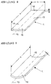
- the stiffening insert (1) undergoes a bend which, when viewed from the side, essentially turns upside down Due to this bend, the bending stiffness of the stiffening insert (1) with respect to a bending of the lateral edges (17) upwards may increase drastically. This effect is extremely important for the present invention. It is thus possible to use the stiffening insert (1 ) at least somewhat elastic and conformable to the shoulder contour and at the same time to achieve a very high transverse stability of the stiffening insert (1).
- thermoplastic Materials that can be used are extrusion, Injection molding, injection blow molding, extrusion blow molding, calendering, Thermoforming, pressing, sintering, compact coating, Foam painting, dipping, pouring, rotary molding, Coating and dipping bubbles.
- a thermosetting material is a suitable manufacturing process block and mold foaming, casting, spraying, Pressing, hot curing, continuous lamination, hand lamination, Profile drawing, fiber spraying process, injection process, Winding, spinning, wet pressing, pressing Resin mats and molding compounds, casting process and filling.
- the stiffening insert in the transverse direction Completely rigid to the longitudinal axis (16) of the carrier (13) be. However, it is preferably - as with the values of bending strength shown above - slightly elastic and gives with the movement of the wearer at least a little after.
- a stiffening insert (1) is used, the Achieving maximum lateral stability is a very big one Has modulus of elasticity, so a bendability Stiffening insert (1) at least in the longitudinal direction of the Carrier (13) for example by attaching a variety of closely spaced notches on the Bottom of the stiffening insert (1) can be brought about. These notches preferably run continuously the entire bottom of the stiffening insert and rectangular to their longitudinal axis and parallel to each other.
- stiffening insert (1) that has a small modulus of elasticity and consequently only a small one Having lateral stability can increase the lateral stability for example by attaching over the whole Width of the stiffening insert (1) and essentially web-shaped extending at right angles to their longitudinal axis (16) Reinforcing ribs on the bottom and / or Top of the stiffening insert (1).
- the stiffening insert (1) can, for example, in the form of a simple, bare plastic plate. To increase comfort is the bottom of the mostly hard Stiffening insert (1) against the shoulder area, however usually padded.
- the Underside of the stiffening insert (1) a foam cushion, its dimensions to the stiffening insert (1) are adjusted or these in the longitudinal and / or transverse direction at least partially tower over.
- foam cushion for example one with a highly viscous liquid or a reversible one or non-reversibly deformable, elastic Material filled pillow on the underside of the stiffening insert (1) can be provided.
- Such a pillow comprises, for example, a pillow-shaped one Protective film made of a flexible material that the content of the pillow is not resolved or dissolved.
- this pillow-shaped protective film becomes the elastic, deformable Material inserted and then closed one preferably the insertion opening of the protective film irreversible, for example by welding or gluing.
- the flexible protective cover As a material for the flexible protective cover are in particular at least some elastic plastics like polyurethanes (PU) to consider.
- PU polyurethanes
- Silicones, gels or gel-like slurries are used in particular to fill the pillow-shaped protective film.
- the gel slurries are, for example, mixtures of water, glycerol or alcohol with swelling agents such as starch or agar or with small organic or inorganic particles such as silica gel. Silicones are preferred because their degree of crosslinking and thus their plastic properties can be set precisely to specified values.
- gases such as air, carbon monoxide, carbon dioxide or noble gases can also be used to fill the protective film. With the term deformable material (2) "are therefore also gases.
- thermoplastic material can also be particularly advantageous to use the pillow-shaped Protective film with a thermoplastic material too to fill.
- this thermoplastic Material By briefly heating this thermoplastic Material can the carrier (13) or the padding in the support area exactly the anatomical Adjusted conditions of the bra of the bra become. In this way, pressure points can be safely avoided become and the comfort increases to an optimum.
- stiffening insert (1) even a molding process undergo and the anatomical conditions can be adjusted.
- At least one such larger pillow that with a plastic, deformable material (2) is filled, can directly on the underside of a stiffening insert (1) for example with the help of gluing, welding or Velcro fastening may be attached.
- the pillow significantly smaller than train the stiffening insert and several of them the underside of the stiffening insert (1). From A particular advantage in this case is that the pillows are targeted can be positioned at those points those with an excessive pressure load are expected got to. Those not related to the underside of the pillow Skin areas can breathe freely. This leads in particular at high outside temperatures to a significant increase comfort.
- a protective film can be used come that loose before filling on the bottom of the Stiffening insert (1) rests and its edges with the Edge area of the stiffening insert, for example, sealing are connected by welding or gluing. After filling with a plastically deformable material in this case too the filling area is preferably through sealed gluing or welding.
- the padding has proven to be particularly advantageous the stiffening insert (1) itself within one pillow-shaped protective film (3) must be provided ( Figures 4, 5 and 6).
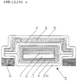
- Figure 4 shows a cross section through an inventive Bra (13) of bras with a stiffening insert (1) inside a pillow-shaped Protective film (3) is arranged.
- a stiffening insert (1) inside a pillow-shaped Protective film (3) is arranged.
- the Top of the stiffening insert (1) with the inside the pillow-shaped protective film (3) at least partially for Example by welding or gluing in contact. This prevents it from being used a gas or a highly viscous liquid as plastically deformable material (2), this on exposure pressure from below to above the top of the Stiffening insert (1) lying area flows.
- the underside of the stiffening insert (1) is from the pillow-shaped protective film (3) covering the stiffening insert (1) encloses on all sides, at least something and at least partially spaced. In that through this spacing formed space is the deformable material (2).
- the stiffening insert (1) which may be a pillow-shaped, includes shoulder padding (2) to increase of comfort in a casing (4) become.
- the casing (4) is preferably designed such that the stiffening insert, if necessary together with the cushion-shaped padding, encloses on all sides.
- the casing (4) can be made of synthetic or natural Textile material exist. It is preferably made from a cotton jersey manufactured.
- the stiffening insert (1) if necessary subsequently, in the already sewn together, at least one upper side (9) and one lower side (5) inserting the comprehensive support (13), positioned and by two perpendicular to the longitudinal axis of the beam (13), only a little of the stiffening insert (1) spaced seams can be locked.
- the stiffening insert (1) from the carrier (13) be removed. This also leads to the advantage that in Depending on the clothing intended to be padded Cushions (2) of different thickness are used can come.
- the side seam that the top of the beam (9) connects to the underside of the carrier (5) interrupted be. Then are preferably in the longitudinal direction of the carrier (13) immediately in front of and behind the stiffening insert (1) Seams provided that are perpendicular to the longitudinal axis of the wearer. This way, a bag formed which has a lateral engagement via a slit-shaped Opening allowed. To close The bag can be broken in the area
- Seam for example, Velcro straps, snap fasteners or a zipper be provided.
- the opening can be closed using a zipper.
- Such slot-shaped openings (12) can on the underside of the beam (5) in the side Edge area of the carrier (13) and parallel to it Be designed to extend longitudinally. Are preferred but directly in the longitudinal direction of the carrier (13) provided in front of or behind the stiffening insert (1) and run at right angles to the longitudinal axis of the carrier (13).
- FIG. 3 A particularly preferred embodiment of the present Invention with a bag for the reversible inclusion of a Stiffening insert (1) is shown in Figures 3,4,5 and 6 shown.
- Figure 3 shows a bottom view of an embodiment the present invention with a pocket for integrated recording of a stiffening insert (1).
- Figure 5 shows a longitudinal section along the line B-B in Figure 3 in the area of the stiffening insert (1).
- the stiffening insert provided with padding (2) (1) is surrounded by a casing (4) in one pocket-shaped space with two possibilities of intervention (12).
- the carrier underside (5) is in this embodiment trained in three parts. It comprises two upper parts (5a) and a central one that at least somewhat overlaps lower part (5b).
- the upper parts (5a) of the carrier underside (5) extend from the respective free end (14) of the carrier (13) so far in the direction of the stiffening insert (1) that seen in the longitudinal direction of the carrier (13), the front or at least slightly overlap the rear end.
- the lower part (5b) of the carrier underside (5) extends below the upper parts (5a) essentially above the length of the stiffening insert (1) and overlaps the in Direction of the stiffening insert (1) facing ends of the upper part (5a) of the carrier underside (5) at least marginally.
- Figure 4 shows a cross section through the one in Figure 3 illustrated embodiment of the present invention with a pocket along the line A-A. From figure 4 clearly shows that the lateral edge area of the lower part (5b) of the carrier underside (5) with the lateral edge area of the upper side of the support (9) indirectly or directly related. This connection can for example by a seam, a weld or a Gluing done.
- a cross section along the line C-C from Figure 3 is shown in Figure 6.
- Figure 6 thus shows the area in which the upper part (5a) of the Carrier underside (5) the lower part (5b) of the carrier underside (5) at least slightly overlapped. It is clearly too recognize that the lateral edge area of the upper Part (5a) of the carrier underside (5) with the carrier top (9) is directly or indirectly related.
- the in Direction of the free ends (14) of the carrier (13) pointing Ends of the upper parts (5a) of the carrier underside and lower part (5b) of the carrier underside (5) is not immediately one above the other, but to each other in the longitudinal direction of the carrier (13).
- the extent of the shift usually increases with increasing Thickness of the stiffening insert (1), if necessary a padding (2) and a casing (4) comprises.
- a flat cushion pad (8) provided to the transition from the free ends (14) of the carrier (13) or from the shoulder area to that from the stiffening insert (1) supported area as inconspicuously as possible design.
- This cushion pad (8) can consist of foam, for example, on its Smooth top and bottom and closed or open-pore is trained. However, it preferably comprises one or several layers of fiberfill or one or more layers of cotton.
- the upholstery from slipping (8) and / or the intermediate layer (7) can be lateral, parallel edges extending to the longitudinal axis of the carrier (13) with the lateral edge areas of the upper side of the support (9) and the underside (5) of the carrier is sewn, welded or glued be (see Figure 4).
- the lateral, outer edges of the girder top (9) and the girder underside (5) can lie parallel above one another ( Figure 2).
- the side edge of the carrier reveals any cut surfaces of the individual, layer-like components of the carrier that may be frayed, as a result of which the aesthetics of the carrier are adversely affected.
- the lateral edge of the upper side of the carrier (9) preferably encloses the lateral edge of the lower side of the carrier (5) like a clamp.
- a preferably at least some elastic band (6) are provided, which is substantially parallel to The longitudinal axis of the carrier (13) runs (see Figure 4). If this is a decorative ribbon, this comes additionally an aesthetic function too.
- the invention Support due to the integrated stiffening insert (1) has an excellent transverse stability that leads to a leads to maximum comfort. Because of the even Distribution of the possibly high breast weight a large support surface will cut into the Avoid shoulder area. As a result, the circulation lymphatic fluid in the shoulder and neck area, in contrast to bras of the prior art Technology, not restricted or even prevented. Thanks to the sturdy design of the stiffening insert (1) a U-shaped upstanding of the side edges of the Carrier (13) was not observed. For this reason, draws the wearer of the invention does not wear clothing unfavorably.
Landscapes
- Engineering & Computer Science (AREA)
- Textile Engineering (AREA)
- Corsets Or Brassieres (AREA)
- Inert Electrodes (AREA)
- Die Bonding (AREA)
- Ceramic Products (AREA)
- Connection Of Batteries Or Terminals (AREA)
- Nonmetallic Welding Materials (AREA)
Description
- a =
- Länge der Versteifungseinlage (1)
- C =
- Materialstärke der Versteifungseinlage (1)
- σ1 =
- Normalspannung bei 0,05 % Dehnung
- σ2 =
- Normalspannung bei 0,25 % Dehnung
- ε1 =
- εt1 = Dehnung von 0,05 %
- ε2 =
- εt2 = Dehnung von 0,25 %
- F =
- Kraft
- Ao =
- Anfangsquerschnitt
- Δl =
- Änderung der Meßlänge, die durch die Kraft F bewirkt wird
- lo =
- Anfangslänge

Claims (11)
- Träger von Büstenhaltern mit einer Trägeroberseite (9), einer Trägerunterseite (5), mindestens einer im Bereich des Scheitelpunktes (15) des Trägers (13) zwischen der Trägeroberseite (9) und der Trägerunterseite (5) in einem taschenförmigen Raum vorgesehenen, im wesentlichen quadratischen, rechteckigen oder plattenförmige Versteifungseinlage (1) sowie mit mindestens einer schlitzförmigen Öffnung (12) zur Einführung und/oder Entnahme der Versteifungseinlage(1), dadurch gekennzeichnet, daß die Trägerunterseite (5) mindestens einen oberen Teil (5a) und einen zentralen unteren Teil (5b) umfaßt, wobei sich zumindest ein oberer Teil (5a) soweit in Richtung der am Scheitelpunkt (15) positionierten Versteifungseinlage (1) erstreckt, daß er, in Längsrichtung des Trägers (13) gesehen, deren vorderes oder hinteres Ende zumindest etwas überlappt und wobei sich der untere, zentrale Teil (5b) im wesentlichen über die Länge der Versteifungseinlage (1) erstreckt und die in Richtung der Versteifungseinlage (1) weisenden Enden des oberen Teils (5a) zumindest geringfügig überlappt, so daß beim Abheben des überlappenden Endes des unteren Teils (5b) nach unten die schlitzförmige Öffnung (12) zum Vorschein kommt.
- Träger nach Anspruch 1, dadurch gekennzeichnet, daß die Versteifungseinlage (1) eine Breite (b) im Bereich von 1,0 bis 15 cm, eine Länge (a) im Bereich von 1,0 bis 60 cm und eine Materialstärke (c) im Bereich von 0,01 bis 30 mm aufweist.
- Träger nach Anspruch 1 oder 2, dadurch gekennzeichnet, daß die Biegesteifigkeit der eben ausgerichteten Versteifungseinlage (1) bezüglich einer Biegung der seitlichen, im wesentlichen parallel zur Längsachse (16) des Trägers (13) verlaufenden Ränder (17) nach oben im Bereich von 10 bis 280000 N·mm2 liegt.
- Träger nach einem der Ansprüche 1 bis 3, dadurch gekennzeichnet, daß an der Unterseite der Versteifungseinlage (1) eine oder mehrere Kerben vorgesehen sind, die zumindest teilweise über die Unterseite der Versteifungseinlage (1) und im wesentlichen rechtwinklig zur Längsachse des Trägers (13) sowie parallel zueinander verlaufen.
- Träger nach einem der Ansprüche 1 bis 4, dadurch gekennzeichnet, daß auf der Unter- und/oder Oberseite der Versteifungseinlage (1) eine oder mehrere stegförmige Verstärkungsrippen angebracht sind, die im wesentlichen rechtwinklig zur Längsachse des Trägers (13) sowie parallel zueinander verlaufen.
- Träger nach einem der vorhergehenden Ansprüche, dadurch gekennzeichnet, daß die Versteifungseinlage (1) aus Metall, Holz, Kork, Leder, Kunststoff, Latex oder Gummi, oder aus Kombinationen hiervon, gebildet ist.
- Träger nach einem der vorhergehenden Ansprüche, dadurch gekennzeichnet, daß die Versteifungseinlage (1) zumindest auf ihrer Unterseite eine Abpolsterung gegenüber der Schulter aufweist, wobei diese Abpolsterung ein Schaumstoffkissen ist und/oder eine im wesentlichen kissenförmige Schutzfolie (3) umfaßt, die mit einem Gas, einer Flüssigkeit, einem Gel, einem bei Raumtemperatur verformbaren Material oder einem thermoplastischen Material gefüllt ist.
- Träger nach einem der vorhergehenden Ansprüche, dadurch gekennzeichnet, daß die Versteifungseinlage (1) innerhalb einer sie ganzseitig umgebenden, kissenförmigen Schutzfolie (3) vorgesehen ist, wobei die Oberseite der Versteifungseinlage (1) zumindest teilweise mit dem ihr gegenüberliegenden Bereich der Schutzfolie (3) in Kontakt steht und wobei der Raum zwischen der Unterseite der Versteifungseinlage (1) und dem ihr gegenüberliegenden Bereich der Schutzfolie (3) mit einem Schaumstoff, einem Gas, einer Flüssigkeit, einem Gel, einem bei Raumtemperatur verformbaren Material oder einem thermoplastischen Material gefüllt ist.
- Träger nach einem der vorhergehenden Ansprüche, dadurch gekennzeichnet, daß die Versteifungseinlage (1) von einer Ummantelung (4) ganzseitig umgeben ist und eine oder mehrere flächige Polsterauflagen (8) und/oder eine oder mehrere Zwischenlagen (7) oberhalb der Versteifungseinlage (1) vorgesehen sind.
- Träger nach einem der vorhergehenden Ansprüche, dadurch gekennzeichnet, daß in der linken und/oder rechten seitlichen Flanke des Trägers (13) im Bereich des Aufeinandertreffens der Trägeroberseite (9) und der Trägerunterseite (5), auf der Unterseite (5) des Trägers mindestens eine im wesentlichen schlitzförmige Öffnung (12) ausgebildet ist, die mit einem im wesentlichen am Scheitelpunkt (15) befindlichen inneren taschenförmigen Raum in Verbindung steht, dessen Abmessungen mindestens den Abmessungen der Versteifungseinlage (1) entsprechen, wobei die Abmessungen der Öffnung (12) mindestens so groß sind, daß die Versteifungseinlage (1) durch sie geführt werden kann.
- Träger nach Anspruch 10, dadurch gekennzeichnet, daß die in Richtung der freien Enden (14) des Trägers (13) weisenden Enden des oberen Teils (5a) und des unteren Teils (5b) in Längsrichtung des Trägers (13) versetzt sind.
Applications Claiming Priority (3)
| Application Number | Priority Date | Filing Date | Title |
|---|---|---|---|
| DE29500894U | 1995-01-23 | ||
| DE29500894U DE29500894U1 (de) | 1995-01-23 | 1995-01-23 | Träger von Büstenhaltern |
| PCT/DE1996/000073 WO1996022708A1 (de) | 1995-01-23 | 1996-01-11 | Träger von büstenhaltern |
Publications (2)
| Publication Number | Publication Date |
|---|---|
| EP0810832A1 EP0810832A1 (de) | 1997-12-10 |
| EP0810832B1 true EP0810832B1 (de) | 1999-08-04 |
Family
ID=8002752
Family Applications (1)
| Application Number | Title | Priority Date | Filing Date |
|---|---|---|---|
| EP96900529A Expired - Lifetime EP0810832B1 (de) | 1995-01-23 | 1996-01-11 | Träger von büstenhaltern |
Country Status (5)
| Country | Link |
|---|---|
| EP (1) | EP0810832B1 (de) |
| AT (1) | ATE182753T1 (de) |
| AU (1) | AU4430596A (de) |
| DE (3) | DE29500894U1 (de) |
| WO (1) | WO1996022708A1 (de) |
Cited By (2)
| Publication number | Priority date | Publication date | Assignee | Title |
|---|---|---|---|---|
| DE20204796U1 (de) * | 2002-03-26 | 2003-08-07 | Mayser GmbH & Co. KG, 88161 Lindenberg | Trägerband für Unterbekleidungs- und Sportbekleidungsstücke |
| EP1635659A4 (de) * | 2003-06-19 | 2010-07-14 | Hbi Branded Apparel Entpr Llc | Kisseneinlage für gurte |
Families Citing this family (1)
| Publication number | Priority date | Publication date | Assignee | Title |
|---|---|---|---|---|
| DE19961407C2 (de) * | 1999-12-20 | 2001-10-18 | Triumph International Ag | Damenunterbekleidungsstück mit einem ausgearbeiteten Büstenteil, wie z.B. Büstenhalter, Einteiler oder dergl. und Verfahren zum Herstellen eines Trägers hierfür |
Family Cites Families (5)
| Publication number | Priority date | Publication date | Assignee | Title |
|---|---|---|---|---|
| FR837713A (fr) * | 1937-05-07 | 1939-02-20 | épaulettes | |
| FR973507A (fr) * | 1950-03-16 | 1951-02-12 | Ruban creux avec baleine intérieure amovible et boutonnière de passage pour bridesde soutien-gorge, lingerie ou similaires | |
| FR1243756A (fr) * | 1958-12-29 | 1960-10-14 | épaulette pour sous-vêtements ou analogue | |
| US4100924A (en) * | 1977-06-16 | 1978-07-18 | Rosenberg Frieda M | Shoulder strap |
| GB8923453D0 (en) * | 1989-10-18 | 1989-12-06 | Karrimor Int Ltd | A rucksack harness shoulder pad |
-
1995
- 1995-01-23 DE DE29500894U patent/DE29500894U1/de not_active Expired - Lifetime
-
1996
- 1996-01-11 WO PCT/DE1996/000073 patent/WO1996022708A1/de not_active Ceased
- 1996-01-11 DE DE19680040T patent/DE19680040D2/de not_active Expired - Fee Related
- 1996-01-11 AU AU44305/96A patent/AU4430596A/en not_active Abandoned
- 1996-01-11 AT AT96900529T patent/ATE182753T1/de not_active IP Right Cessation
- 1996-01-11 DE DE59602625T patent/DE59602625D1/de not_active Expired - Fee Related
- 1996-01-11 EP EP96900529A patent/EP0810832B1/de not_active Expired - Lifetime
Cited By (2)
| Publication number | Priority date | Publication date | Assignee | Title |
|---|---|---|---|---|
| DE20204796U1 (de) * | 2002-03-26 | 2003-08-07 | Mayser GmbH & Co. KG, 88161 Lindenberg | Trägerband für Unterbekleidungs- und Sportbekleidungsstücke |
| EP1635659A4 (de) * | 2003-06-19 | 2010-07-14 | Hbi Branded Apparel Entpr Llc | Kisseneinlage für gurte |
Also Published As
| Publication number | Publication date |
|---|---|
| DE19680040D2 (de) | 1998-02-26 |
| EP0810832A1 (de) | 1997-12-10 |
| DE29500894U1 (de) | 1995-03-16 |
| AU4430596A (en) | 1996-08-14 |
| ATE182753T1 (de) | 1999-08-15 |
| WO1996022708A1 (de) | 1996-08-01 |
| DE59602625D1 (de) | 1999-09-09 |
Similar Documents
| Publication | Publication Date | Title |
|---|---|---|
| DE2535058C2 (de) | Wegwerfwindel | |
| DE68919881T2 (de) | Anti-Wellen-Förderband. | |
| DE2812968A1 (de) | Schuh mit sohle und oberteil fuer sportliche betaetigung im allgemeinen und training | |
| DE202015002525U1 (de) | Fixierhilfe zum einfachen Fixieren von Nähkleidern auf Trägerteilen | |
| EP1910597B1 (de) | Verfahren zur Herstellung eines FORMANGEPASSTEn ABSTANDSGEWIRKEs | |
| DE3525006C2 (de) | ||
| EP1776023B1 (de) | Verbindungselement für miteinander zu verbindende endbereiche von bekleidungsstücken | |
| DE1941566C3 (de) | Tragtasche mit einem vorzugsweise aus zwei Schnüren bestehenden Schnurzug sowie Verfahren und Vorrichtung zum Herstellen einer solchen | |
| DE69024498T2 (de) | Schulterpolster für einen rucksackträger | |
| DE102011119320B4 (de) | Verkleidungsteil mit einem Halteprofil zum Positionieren einer zwei Dekorschichten verbindenden Naht | |
| DD300069A5 (de) | Einzugstab zur profilformung von polstermaterialien | |
| DE29500894U1 (de) | Träger von Büstenhaltern | |
| DE19501729C2 (de) | Träger von Büstenhaltern | |
| DE202006002470U1 (de) | Schutzdecke | |
| DE2622477C3 (de) | Rückenteil für einen Rucksack | |
| AT407692B (de) | Uhrarmband | |
| DE202010016550U1 (de) | Verbundteil mit Schweißverbindung | |
| DE202009005435U1 (de) | Kleidungsstück mit Körbchen | |
| DE69800123T2 (de) | Hygienischer Artikel mit einem Flächenreissverschluss | |
| DE2613415A1 (de) | Schultasche | |
| DE1429357C (de) | Polster fur Sitzmöbel | |
| DE19512842C2 (de) | Befestigungsband | |
| AT403980B (de) | Sandwichbauteil, insbesondere für eine uhr | |
| DE2010993A1 (de) | Verfahren zum Einfuhren des Randes eines Flachwerkstoffes in einen U förmig profi lierten Fassungsrand | |
| DE202004013334U1 (de) | Tablett |
Legal Events
| Date | Code | Title | Description |
|---|---|---|---|
| PUAI | Public reference made under article 153(3) epc to a published international application that has entered the european phase |
Free format text: ORIGINAL CODE: 0009012 |
|
| 17P | Request for examination filed |
Effective date: 19970818 |
|
| AK | Designated contracting states |
Kind code of ref document: A1 Designated state(s): AT BE CH DE FR GB IT LI NL SE |
|
| 17Q | First examination report despatched |
Effective date: 19980402 |
|
| GRAG | Despatch of communication of intention to grant |
Free format text: ORIGINAL CODE: EPIDOS AGRA |
|
| GRAG | Despatch of communication of intention to grant |
Free format text: ORIGINAL CODE: EPIDOS AGRA |
|
| GRAH | Despatch of communication of intention to grant a patent |
Free format text: ORIGINAL CODE: EPIDOS IGRA |
|
| GRAH | Despatch of communication of intention to grant a patent |
Free format text: ORIGINAL CODE: EPIDOS IGRA |
|
| GRAA | (expected) grant |
Free format text: ORIGINAL CODE: 0009210 |
|
| AK | Designated contracting states |
Kind code of ref document: B1 Designated state(s): AT BE CH DE FR GB IT LI NL SE |
|
| PG25 | Lapsed in a contracting state [announced via postgrant information from national office to epo] |
Ref country code: SE Free format text: THE PATENT HAS BEEN ANNULLED BY A DECISION OF A NATIONAL AUTHORITY Effective date: 19990804 Ref country code: NL Free format text: LAPSE BECAUSE OF FAILURE TO SUBMIT A TRANSLATION OF THE DESCRIPTION OR TO PAY THE FEE WITHIN THE PRESCRIBED TIME-LIMIT Effective date: 19990804 Ref country code: IT Free format text: LAPSE BECAUSE OF FAILURE TO SUBMIT A TRANSLATION OF THE DESCRIPTION OR TO PAY THE FEE WITHIN THE PRE;WARNING: LAPSES OF ITALIAN PATENTS WITH EFFECTIVE DATE BEFORE 2007 MAY HAVE OCCURRED AT ANY TIME BEFORE 2007. THE CORRECT EFFECTIVE DATE MAY BE DIFFERENT FROM THE ONE RECORDED.SCRIBED TIME-LIMIT Effective date: 19990804 Ref country code: GB Free format text: LAPSE BECAUSE OF FAILURE TO SUBMIT A TRANSLATION OF THE DESCRIPTION OR TO PAY THE FEE WITHIN THE PRESCRIBED TIME-LIMIT Effective date: 19990804 Ref country code: FR Free format text: LAPSE BECAUSE OF FAILURE TO SUBMIT A TRANSLATION OF THE DESCRIPTION OR TO PAY THE FEE WITHIN THE PRESCRIBED TIME-LIMIT Effective date: 19990804 |
|
| REF | Corresponds to: |
Ref document number: 182753 Country of ref document: AT Date of ref document: 19990815 Kind code of ref document: T |
|
| REG | Reference to a national code |
Ref country code: CH Ref legal event code: EP |
|
| REF | Corresponds to: |
Ref document number: 59602625 Country of ref document: DE Date of ref document: 19990909 |
|
| EN | Fr: translation not filed | ||
| NLV1 | Nl: lapsed or annulled due to failure to fulfill the requirements of art. 29p and 29m of the patents act | ||
| PG25 | Lapsed in a contracting state [announced via postgrant information from national office to epo] |
Ref country code: AT Free format text: LAPSE BECAUSE OF NON-PAYMENT OF DUE FEES Effective date: 20000111 |
|
| PG25 | Lapsed in a contracting state [announced via postgrant information from national office to epo] |
Ref country code: LI Free format text: LAPSE BECAUSE OF NON-PAYMENT OF DUE FEES Effective date: 20000131 Ref country code: CH Free format text: LAPSE BECAUSE OF NON-PAYMENT OF DUE FEES Effective date: 20000131 Ref country code: BE Free format text: LAPSE BECAUSE OF NON-PAYMENT OF DUE FEES Effective date: 20000131 |
|
| GBV | Gb: ep patent (uk) treated as always having been void in accordance with gb section 77(7)/1977 [no translation filed] |
Effective date: 19990804 |
|
| PLBE | No opposition filed within time limit |
Free format text: ORIGINAL CODE: 0009261 |
|
| STAA | Information on the status of an ep patent application or granted ep patent |
Free format text: STATUS: NO OPPOSITION FILED WITHIN TIME LIMIT |
|
| 26N | No opposition filed | ||
| BERE | Be: lapsed |
Owner name: MORITZ MANFRED Effective date: 20000131 |
|
| REG | Reference to a national code |
Ref country code: CH Ref legal event code: PL |
|
| PG25 | Lapsed in a contracting state [announced via postgrant information from national office to epo] |
Ref country code: DE Free format text: LAPSE BECAUSE OF NON-PAYMENT OF DUE FEES Effective date: 20001101 |