EP0810684A2 - Brennstoffzelle mit geschmolzenen Karbonaten - Google Patents
Brennstoffzelle mit geschmolzenen Karbonaten Download PDFInfo
- Publication number
- EP0810684A2 EP0810684A2 EP97108150A EP97108150A EP0810684A2 EP 0810684 A2 EP0810684 A2 EP 0810684A2 EP 97108150 A EP97108150 A EP 97108150A EP 97108150 A EP97108150 A EP 97108150A EP 0810684 A2 EP0810684 A2 EP 0810684A2
- Authority
- EP
- European Patent Office
- Prior art keywords
- fuel
- electrode
- gas
- air
- molten carbonate
- Prior art date
- Legal status (The legal status is an assumption and is not a legal conclusion. Google has not performed a legal analysis and makes no representation as to the accuracy of the status listed.)
- Granted
Links
Images


Classifications
-
- H—ELECTRICITY
- H01—ELECTRIC ELEMENTS
- H01M—PROCESSES OR MEANS, e.g. BATTERIES, FOR THE DIRECT CONVERSION OF CHEMICAL ENERGY INTO ELECTRICAL ENERGY
- H01M8/00—Fuel cells; Manufacture thereof
- H01M8/14—Fuel cells with fused electrolytes
- H01M8/141—Fuel cells with fused electrolytes the anode and the cathode being gas-permeable electrodes or electrode layers
- H01M8/142—Fuel cells with fused electrolytes the anode and the cathode being gas-permeable electrodes or electrode layers with matrix-supported or semi-solid matrix-reinforced electrolyte
-
- H—ELECTRICITY
- H01—ELECTRIC ELEMENTS
- H01M—PROCESSES OR MEANS, e.g. BATTERIES, FOR THE DIRECT CONVERSION OF CHEMICAL ENERGY INTO ELECTRICAL ENERGY
- H01M8/00—Fuel cells; Manufacture thereof
- H01M8/04—Auxiliary arrangements, e.g. for control of pressure or for circulation of fluids
- H01M8/04082—Arrangements for control of reactant parameters, e.g. pressure or concentration
- H01M8/04089—Arrangements for control of reactant parameters, e.g. pressure or concentration of gaseous reactants
-
- H—ELECTRICITY
- H01—ELECTRIC ELEMENTS
- H01M—PROCESSES OR MEANS, e.g. BATTERIES, FOR THE DIRECT CONVERSION OF CHEMICAL ENERGY INTO ELECTRICAL ENERGY
- H01M8/00—Fuel cells; Manufacture thereof
- H01M8/14—Fuel cells with fused electrolytes
- H01M2008/147—Fuel cells with molten carbonates
-
- H—ELECTRICITY
- H01—ELECTRIC ELEMENTS
- H01M—PROCESSES OR MEANS, e.g. BATTERIES, FOR THE DIRECT CONVERSION OF CHEMICAL ENERGY INTO ELECTRICAL ENERGY
- H01M2300/00—Electrolytes
- H01M2300/0017—Non-aqueous electrolytes
- H01M2300/0048—Molten electrolytes used at high temperature
- H01M2300/0051—Carbonates
-
- Y—GENERAL TAGGING OF NEW TECHNOLOGICAL DEVELOPMENTS; GENERAL TAGGING OF CROSS-SECTIONAL TECHNOLOGIES SPANNING OVER SEVERAL SECTIONS OF THE IPC; TECHNICAL SUBJECTS COVERED BY FORMER USPC CROSS-REFERENCE ART COLLECTIONS [XRACs] AND DIGESTS
- Y02—TECHNOLOGIES OR APPLICATIONS FOR MITIGATION OR ADAPTATION AGAINST CLIMATE CHANGE
- Y02E—REDUCTION OF GREENHOUSE GAS [GHG] EMISSIONS, RELATED TO ENERGY GENERATION, TRANSMISSION OR DISTRIBUTION
- Y02E60/00—Enabling technologies; Technologies with a potential or indirect contribution to GHG emissions mitigation
- Y02E60/30—Hydrogen technology
- Y02E60/50—Fuel cells
Definitions
- the invention relates to a molten carbonate fuel cell which directly converts chemical energy of fuel into electric energy.
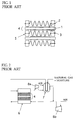
- a molten carbonate fuel cell generally includes cells 4, and separators 5 sandwiching the cell 4 therebetween.
- the cell 4 includes an anode or a fuel electrode 2, a cathode or an air electrode 3, and a thin planar electrolytic plate 1 sandwiched between the fuel and air electrodes 2 and 3.
- a single cell 4 could provide a low voltage, specifically about 0.8 V.
- many cells 4 are piled with the separators 5 being sandwiched between the cells 4, to thereby generate a higher voltage.
- Anode gas containing hydrogen is supplied to the fuel electrode 2, and cathode gas containing oxygen is supplied to the air electrode 3 through manifolds (not illustrated). Then, chemical reaction is made to occur at each of the cells 4 at high temperature, specifically at about 650 °C to thereby generate electricity, which is taken out in a direction perpendicular to a plane of each of the cells (namely, a vertical direction in Fig. 1). Electrolyte (molten carbonate) contained in the electrolytic plate 1 is molten at the above mentioned temperature, and wetting between the molten electrolytic plate 1 and the separator 5 ensures gas sealing between the separators 5.
- Fig. 2 schematically illustrates a generating set including the above mentioned fuel cell for generating electricity using natural gas as fuel.
- the illustrated generating set includes a molten carbonate fuel cell 6 (hereinafter, referred to simply as a fuel cell) including a plurality of the cells 4 piled one on another, a reformer 7 using natural gas as fuel, a gas blower 8a, and an air compressor 8b. Natural gas is reformed in a reforming tube in the reformer 7 into anode gas containing hydrogen, and the thus reformed anode gas is supplied to an anode of the fuel cell 6 for generating electricity.
- a molten carbonate fuel cell 6 hereinafter, referred to simply as a fuel cell
- Natural gas is reformed in a reforming tube in the reformer 7 into anode gas containing hydrogen, and the thus reformed anode gas is supplied to an anode of the fuel cell 6 for generating electricity.
- Exhaust gas exhausted out of an anode of the fuel cell 6 is burned in a combustion chamber of the reformer 7 to thereby reform natural gas contained in the reforming tube, and resulting exhaust gas is mixed with cathode gas containing oxygen.
- the gas blower 8a is called carbon dioxide gas recycling blower, because it supplies carbon dioxide (CO 2 ) produced at an anode to the air electrode.
- anode gas (fuel gas or reformed gas) is supplied into a fuel electrode reaction chamber of the fuel cell 6, and make electrode reaction (anode reaction) at the fuel electrode 2.
- the resulting exhaust gas is burned, and then supplied into an air electrode reaction chamber together with air.
- the exhaust gas mixed with air make electrode reaction (cathode reaction) and at the same time remove heat generated in the fuel cell 6.
- the above mentioned fuel electrode 2, electrolytic plate 1, and air electrode 3 keep in sufficient contact with one another for providing cell performances.
- the electrolytic plate 1 is porous so as to sufficiently retain electrolyte therein to thereby prevent occurrence of cross leakage.
- Fig. 3 shows an example of gas composition at inlet and outlet ports of each of the cells 4 of the fuel cell 6.
- anode gas is supplied into a fuel electrode reaction chamber through an inlet port (which is located at the left end in Fig. 3), and flows along the fuel electrode 2, while which hydrogen and carbon monoxide (CO) are consumed in anode reaction.
- unreacted gas together with reaction products such as CO 2 and H 2 O is exhausted through an outlet port (which is located at the right end in Fig. 3) of the reaction chamber.
- reaction products such as CO 2 and H 2 O
- the reduction in electro motive voltage caused by reduction in a fuel concentration is called Nernst loss.
- a problem is that the greater a fuel utilization rate is, the greater Nernst loss is.
- a conventional molten carbonate fuel cell has a problem that the reduction in cell performances caused by Nernst loss is unavoidable, and thus it is difficult to use fuel with high utilization rate.
- a generating set including conventional molten carbonate fuel cells therein needs a carbon dioxide gas recycling system for supplying carbon dioxide gas generated at a fuel electrode to an air electrode, as mentioned above.
- This is accompanied by a problem that load response speed is restricted during transition time in which electricity generation output varies. That is, though an amount of carbon dioxide gas generated at a fuel electrode due to electricity generation is equal to an amount of consumption of carbon dioxide gas at an air electrode, it is quite difficult to operate a generating set in accordance with load fluctuation, because of delay in carbon dioxide gas recycle which is caused by the tube capacity in transition.
- molten carbonate fuel cell which is capable of avoiding reduction in cell performance which would be caused by Nernst loss, operating with high fuel utilization rate, requiring no carbon dioxide gas recycling system, being responsive to rapid fluctuation in load, making a structure of a generating set simpler, and reducing fabrication costs thereof.
- a molten carbonate fuel cell including (a) fuel electrodes, (b) air electrodes, and (c) electrolytic plates sandwiched between the fuel and air electrodes, the fuel electrode, the air electrode and the electrolytic plate cooperating with one another to define a unit cell, the electrolytic plate being formed with a plurality of fine through-holes through which the fuel and air electrodes are in fluid communication with each other, both unreacted gas and gas produced by reaction at the fuel electrode flowing from the fuel electrode to the air electrode through the through-holes.
- both unreacted gas and gas produced by reaction at the fuel electrode flow from the fuel electrode to the air electrode through the through-holes formed with the electrolytic plate, and hence all surfaces of the fuel electrode are exposed to fresh fuel, which avoids reduction in cell performances caused by Nernst loss which is in turn caused by reduction in fuel concentration, thereby it being possible to accomplish operation with a high fuel utilization rate.
- flow rate of fuel is controlled in accordance with load output, so that gas produced by reaction at the fuel electrode and gas which was supplied to the fuel electrode but not reacted flow through the through-holes to generate a pressure difference between the fuel and air electrodes, the pressure difference being equivalent to a pressure loss.
- This embodiment ensures that a required amount of flow rate of fuel is always supplied to a cell in accordance with output load, to thereby reduce an amount of unreacted fuel gas flowing into the air electrode below a few percent, resulting in operation of the cell with a high fuel utilization rate and depression of production of heat caused by residual combustible gas.
- a pressure at the fuel electrode is kept higher than a pressure at the air electrode in accordance with load output to produce a pressure difference between the fuel and air electrodes, so that gas produced by reaction at the fuel electrode and gas which was supplied to the fuel electrode but not reacted flow through the through-holes due to the pressure difference.
- This embodiment ensures that the pressure difference is kept almost zero during OCV in which time electricity is not generated to thereby avoid fuel consumption, and the pressure difference is increased in accordance with output power during electricity is being generated, thereby reducing an amount of unreacted fuel gas flowing into the air electrode below a few percent, resulting in operation of the cell with a high fuel utilization rate and depression of production of heat caused by residual combustible gas.
- the fuel electrode is provided with catalyst for reforming, gas reformed by the catalyst together with unreacted gas and gas produced by reaction at the fuel electrode flowing from the fuel electrode to the air electrode through the through-holes.
- catalyst for reforming gas reformed by the catalyst together with unreacted gas and gas produced by reaction at the fuel electrode flowing from the fuel electrode to the air electrode through the through-holes.
- Fig. 1 is a schematic view illustrating a general molten carbonate fuel cell.
- Fig. 2 is a schematic view illustrating a conventional generating set using natural gas as fuel.
- Fig. 3 is a schematic view of a conventional fuel cell, showing gas composition at inlet and outlet ports of the fuel cell.
- Fig. 4 is a schematic view illustrating an internal structure of a molten carbonate fuel cell in accordance with the present invention.
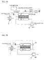
- Fig. 5A is a schematic view illustrating a generating set including a molten carbonate fuel cell in accordance with the present invention.
- Fig. 5B is a schematic view illustrating another generating set including a molten carbonate fuel cell in accordance with the present invention.
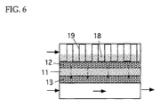
- Fig. 6 is a schematic view illustrating a molten carbonate fuel cell in accordance with another embodiment of the present invention.
- a molten carbonate fuel cell in accordance with the present invention includes a cell 14 comprising a fuel electrode 12, an air electrode 13, and a electrolytic plate 11 sandwiched between the fuel and air electrodes 12 and 13.
- the electrolytic plate 11 is formed with a plurality of fine through-holes 11a through which the fuel and air electrodes 12 and 13 are in fluid communication with each other.
- the electrolytic plate 11 is formed with a plurality of the fine through-holes 11a unlike a conventional electrolytic plate acting merely as a partition wall for separating fuel and air electrodes from each other, to thereby make it possible for unreacted gas and gas produced by reaction at the fuel electrode 12 to flow from the fuel electrode 12 to the air electrode 13.
- the fuel and air electrodes 12 and 13 are originally porous. Thus, gas flows directly through the electrolytic plate 11 by forming the electrolytic plate 11 with the through-holes 11a and producing a pressure difference between the fuel and air electrodes 12 and 13.
- H 2 hydrogen
- CO 3 2- carbonic acid ion
- CO 2 carbon dioxide
- the thus generated moisture and carbon dioxide are supplied directly to the air electrode 13 through the through-holes 11a of the electrolytic plate 11.
- Oxygen (O 2 ) contained in cathode gas reacts with carbon dioxide (CO 2 ) to thereby carbonic acid ion (CO 3 2- ) in cathode reaction occurring at the air electrode 13.
- the carbonic ion is supplied directly to the fuel electrode 12 through electrolyte of the electrolytic plate 11.
- carbonic acid ion which is required for anode reaction and carbon dioxide gas which is required for cathode reaction are in direct circulation within the cell 14.
- particles of which the fuel and air electrodes 12 and 13 are formed are represented with circles 12a and 13a, through which electrons move to thereby generate electricity.
- the fuel electrode receives fuel gas, namely hydrogen and carbon monoxide, from a flow path and also receives carbonic acid ion from a electrolyte, and cause them to react with each other therein, similarly to a conventional fuel electrode.
- fuel gas namely hydrogen and carbon monoxide
- reaction products and unreacted gas are conventionally returned to a fuel electrode flow path, they flow through the fine through-holes 11a of the electrolytic plate and reach the air electrode 13 in the present embodiment.
- gas flow is always unidirectional, and hence a surface of the fuel electrode 12 is always exposed to fresh fuel having a high concentration, resulting in reduction in Nernst loss.
- the electrolytic plate 11 In order to form the electrolytic plate 11 with a plurality of the fine through-holes 11a, coarse particles may be mixed into the electrolytic plate 11 or pore former may be introduced into the electrolytic plate 11.
- Pore former includes polymer which is vaporized by heating, and thus cavities or through-holes 11a can be formed by vaporizing the pore former when the fuel cell is heated. For instance, if the fine through-holes 11a having a diameter of 100 ⁇ m occupies about 5 % in pore volume in the electrolytic plate 11, load of one atom, that is 150 mA/ cm 2 acts as water head of about 1 meter.
- Figs. 5A and 5B illustrate generating sets including a molten carbonate fuel cell in accordance with the present invention.
- a molten carbonate fuel cell in accordance with the present invention has no outlet port for gas (anode exhaust gas) passing through a reaction chamber of the fuel electrode to be discharged therethrough, and hence exhaust gas is not discharged from the fuel electrode. All amount of gas supplied to the fuel electrode including gas produced by reaction at the fuel electrode and unreacted gas which was supplied to the fuel electrode, but not reacted is made to flow into a cathode through a plurality of the fine through-holes 11a formed with the electrolytic plate 11.
- a flow rate of fuel is controlled by a fuel flow rate adjust valve 17 in accordance with load output to thereby flow gas produced by reaction at the fuel electrode and unreacted gas which was supplied to the fuel electrode, but not reacted, into a cathode through a plurality of the fine through-holes 11a formed with the electrolytic plate 11.
- a generating set may include a differential pressure gage 16 for detecting a differential pressure between the fuel and air electrodes, and a flow rate adjust valve 17 for controlling an amount of gas in accordance with outputs of the differential pressure gage 16.
- a pressure at the fuel electrode is kept higher than a pressure at the air electrode, and gas in an amount to be determined in accordance with load output can be flown into the air electrode from the fuel electrode due to a pressure difference between the fuel and air electrodes.
- Fig. 6 illustrates a molten carbonate fuel cell in accordance with another embodiment of the present invention.
- the fuel cell is provided at the fuel electrode 12 thereof with a porous flow path plate 19 and catalyst 18 for reforming. Generated electricity is taken out through the porous flow path plate 19. Gas reformed by the catalyst 18 together with unreacted gas and gas produced by reaction at the fuel electrode 12 is made to flow from the fuel electrode 12 to the air electrode 13 through the through-holes 11a.
- an internal reform type fuel cell which has a simple structure and which does not need to have an external reformer, which in turn enables a generating set to have a simpler structure.
- the present invention is able to be applied to not only a molten carbonate fuel cell, but also other types of fuel cell.
- a molten carbonate fuel cell in accordance with the present invention is characterized by that (a) Nernst loss is reduced with the result of improvement in cell performances, (b) a carbon dioxide gas recycling system is no longer necessary, and there is no delay in supply of carbon dioxide gas, resulting in that the fuel cell can be readily run, (c) since the fuel cell is of percolation type, the fuel cell can be readily controlled, (d) it is possible to run the fuel cell with high fuel utilization rate, (e) it is possible to form a cell in a simpler structure with the result of cost reduction, and (f) a molten carbonate fuel cell in accordance with the present invention can be applied to an internally reforming type fuel cell.
- a molten carbonate fuel cell in accordance with the present invention provides advantages of no reduction in cell performance which would caused by Nernst loss, capability of fuel consumption with high efficiency, no necessity of carbon dioxide gas recycling system, responsibility to rapid fluctuation in load, making a structure of a generating set simpler, and reduction in fabrication costs.
Landscapes
- Life Sciences & Earth Sciences (AREA)
- Engineering & Computer Science (AREA)
- Manufacturing & Machinery (AREA)
- Sustainable Development (AREA)
- Sustainable Energy (AREA)
- Chemical & Material Sciences (AREA)
- Chemical Kinetics & Catalysis (AREA)
- Electrochemistry (AREA)
- General Chemical & Material Sciences (AREA)
- Fuel Cell (AREA)
Applications Claiming Priority (3)
| Application Number | Priority Date | Filing Date | Title |
|---|---|---|---|
| JP13459996A JP3575650B2 (ja) | 1996-05-29 | 1996-05-29 | 溶融炭酸塩型燃料電池 |
| JP134599/96 | 1996-05-29 | ||
| JP13459996 | 1996-05-29 |
Publications (3)
| Publication Number | Publication Date |
|---|---|
| EP0810684A2 true EP0810684A2 (de) | 1997-12-03 |
| EP0810684A3 EP0810684A3 (de) | 2002-07-03 |
| EP0810684B1 EP0810684B1 (de) | 2005-04-20 |
Family
ID=15132171
Family Applications (1)
| Application Number | Title | Priority Date | Filing Date |
|---|---|---|---|
| EP97108150A Expired - Lifetime EP0810684B1 (de) | 1996-05-29 | 1997-05-20 | Schmelzkarbonat-Brennstoffzelle beinhaltend Elektrolytplatte mit feinen Gaskanälen |
Country Status (5)
| Country | Link |
|---|---|
| US (1) | US5897972A (de) |
| EP (1) | EP0810684B1 (de) |
| JP (1) | JP3575650B2 (de) |
| DE (1) | DE69733041T2 (de) |
| ES (1) | ES2241014T3 (de) |
Cited By (2)
| Publication number | Priority date | Publication date | Assignee | Title |
|---|---|---|---|---|
| US6124053A (en) * | 1998-07-09 | 2000-09-26 | Fuel Cell Technologies, Inc. | Fuel cell with internal combustion chamber |
| US7348087B2 (en) | 2003-07-28 | 2008-03-25 | Hewlett-Packard Development Company, L.P. | Fuel cell with integral manifold |
Families Citing this family (4)
| Publication number | Priority date | Publication date | Assignee | Title |
|---|---|---|---|---|
| US6793711B1 (en) | 1999-12-07 | 2004-09-21 | Eltron Research, Inc. | Mixed conducting membrane for carbon dioxide separation and partial oxidation reactions |
| US6878479B2 (en) * | 2001-06-13 | 2005-04-12 | The Regents Of The University Of California | Tilted fuel cell apparatus |
| US7846601B2 (en) * | 2004-10-08 | 2010-12-07 | Gm Global Technology Operations, Inc. | Fuel cell design and control method to facilitate self heating through catalytic combustion of anode exhaust |
| JP5486743B2 (ja) * | 2010-04-05 | 2014-05-07 | 日本特殊陶業株式会社 | 燃料電池セル及び燃料電池スタック若しくは燃料電池装置 |
Family Cites Families (7)
| Publication number | Priority date | Publication date | Assignee | Title |
|---|---|---|---|---|
| US4643955A (en) * | 1983-04-15 | 1987-02-17 | The United States Of America As Represented By The Department Of Energy | Molten carbonate fuel cell reduction of nickel deposits |
| US4714661A (en) * | 1986-07-08 | 1987-12-22 | The United States Of America As Represented By The United States Department Of Energy | Molten carbonate fuel cell |
| JPS6452385A (en) * | 1987-08-22 | 1989-02-28 | Fuji Electric Res | Electrolyte plate of molten carbonate fuel cell |
| JP3350167B2 (ja) * | 1993-09-03 | 2002-11-25 | 株式会社東芝 | 溶融炭酸塩型燃料電池 |
| JPH07282822A (ja) * | 1994-04-08 | 1995-10-27 | Hitachi Ltd | 燃料電池及び補修方法 |
| US5422195A (en) * | 1994-05-04 | 1995-06-06 | Energy Research Corporation | Carbonate fuel cell with direct recycle of anode exhaust to cathode |
| JPH0812303A (ja) * | 1994-07-05 | 1996-01-16 | Ishikawajima Harima Heavy Ind Co Ltd | プレートリフォーマ |
-
1996
- 1996-05-29 JP JP13459996A patent/JP3575650B2/ja not_active Expired - Fee Related
-
1997
- 1997-05-20 DE DE69733041T patent/DE69733041T2/de not_active Expired - Lifetime
- 1997-05-20 EP EP97108150A patent/EP0810684B1/de not_active Expired - Lifetime
- 1997-05-20 ES ES97108150T patent/ES2241014T3/es not_active Expired - Lifetime
- 1997-05-28 US US08/864,189 patent/US5897972A/en not_active Expired - Lifetime
Cited By (3)
| Publication number | Priority date | Publication date | Assignee | Title |
|---|---|---|---|---|
| US6124053A (en) * | 1998-07-09 | 2000-09-26 | Fuel Cell Technologies, Inc. | Fuel cell with internal combustion chamber |
| US7348087B2 (en) | 2003-07-28 | 2008-03-25 | Hewlett-Packard Development Company, L.P. | Fuel cell with integral manifold |
| US7981560B2 (en) | 2003-07-28 | 2011-07-19 | Eveready Battery Company, Inc. | Fuel cell with integral manifold and laterally spaced electrodes |
Also Published As
| Publication number | Publication date |
|---|---|
| ES2241014T3 (es) | 2005-10-16 |
| JP3575650B2 (ja) | 2004-10-13 |
| DE69733041T2 (de) | 2005-09-29 |
| EP0810684A3 (de) | 2002-07-03 |
| JPH09320619A (ja) | 1997-12-12 |
| DE69733041D1 (de) | 2005-05-25 |
| US5897972A (en) | 1999-04-27 |
| EP0810684B1 (de) | 2005-04-20 |
Similar Documents
| Publication | Publication Date | Title |
|---|---|---|
| US6811913B2 (en) | Multipurpose reversible electrochemical system | |
| AU2002234964C1 (en) | Solid polymer electrolyte fuel cell assembly, fuel cell stack, and method of supplying reaction gas in fuel cell | |
| AU2002219941A1 (en) | Multipurpose reversible electrochemical system | |
| US7163759B2 (en) | Solid oxide fuel cell stack assembly having tapered diffusion layers | |
| JPH1116590A (ja) | 燃料電池 | |
| US20020098397A1 (en) | Catalytic humidifier and heater for the fuel stream of a fuel cell | |
| CN121039845A (zh) | 固体氧化物电池堆叠的模块构造 | |
| US6924049B2 (en) | Electrolysis fuel cell energy plant | |
| US5897972A (en) | Molten carbonate fuel cell | |
| JPH0275164A (ja) | 溶融炭酸塩型燃料電池発電装置および該発電装置の運転方法 | |
| US7122257B2 (en) | Fuel cell reactant supply | |
| US20040121215A1 (en) | Fuel cell | |
| JP6993488B1 (ja) | 燃料電池発電システム、及び、燃料電池発電システムの制御方法 | |
| TWI797800B (zh) | 燃料電池發電系統,以及燃料電池發電系統的控制方法 | |
| JP2595579B2 (ja) | 溶融炭酸塩型燃料電池の発電装置 | |
| US8753784B2 (en) | Separator for molten carbonate fuel cell | |
| JPS63236265A (ja) | 燃料電池 | |
| JP2007128786A (ja) | 燃料電池システム | |
| JPH0615404Y2 (ja) | 内部改質形燃料電池 | |
| JPH06314570A (ja) | 燃料電池のマニホールド構造 | |
| JP4656286B2 (ja) | 燃料電池システム | |
| JPS63158754A (ja) | 内部改質形燃料電池 | |
| JPH06251793A (ja) | 燃料電池のマニホールド | |
| JPH07142073A (ja) | 内部改質燃料電池 | |
| JPH0831321B2 (ja) | 内部改質型溶融炭酸塩燃料電池 |
Legal Events
| Date | Code | Title | Description |
|---|---|---|---|
| PUAI | Public reference made under article 153(3) epc to a published international application that has entered the european phase |
Free format text: ORIGINAL CODE: 0009012 |
|
| AK | Designated contracting states |
Kind code of ref document: A2 Designated state(s): DE ES GB IT NL |
|
| 17P | Request for examination filed |
Effective date: 20010319 |
|
| PUAL | Search report despatched |
Free format text: ORIGINAL CODE: 0009013 |
|
| RIC1 | Information provided on ipc code assigned before grant |
Free format text: 7H 01M 8/14 A, 7H 01M 8/02 B, 7H 01M 8/04 B |
|
| AK | Designated contracting states |
Kind code of ref document: A3 Designated state(s): DE ES GB IT NL |
|
| 17Q | First examination report despatched |
Effective date: 20020925 |
|
| RTI1 | Title (correction) |
Free format text: MOLTEN CARBONATE FUEL CELL COMPRISING ELECTOLYTE PLATE HAVING FINE THROUGH HOLES |
|
| GRAP | Despatch of communication of intention to grant a patent |
Free format text: ORIGINAL CODE: EPIDOSNIGR1 |
|
| GRAS | Grant fee paid |
Free format text: ORIGINAL CODE: EPIDOSNIGR3 |
|
| GRAA | (expected) grant |
Free format text: ORIGINAL CODE: 0009210 |
|
| AK | Designated contracting states |
Kind code of ref document: B1 Designated state(s): DE ES GB IT NL |
|
| REG | Reference to a national code |
Ref country code: GB Ref legal event code: FG4D |
|
| REF | Corresponds to: |
Ref document number: 69733041 Country of ref document: DE Date of ref document: 20050525 Kind code of ref document: P |
|
| REG | Reference to a national code |
Ref country code: ES Ref legal event code: FG2A Ref document number: 2241014 Country of ref document: ES Kind code of ref document: T3 |
|
| PLBE | No opposition filed within time limit |
Free format text: ORIGINAL CODE: 0009261 |
|
| STAA | Information on the status of an ep patent application or granted ep patent |
Free format text: STATUS: NO OPPOSITION FILED WITHIN TIME LIMIT |
|
| 26N | No opposition filed |
Effective date: 20060123 |
|
| PGFP | Annual fee paid to national office [announced via postgrant information from national office to epo] |
Ref country code: NL Payment date: 20160411 Year of fee payment: 20 |
|
| PGFP | Annual fee paid to national office [announced via postgrant information from national office to epo] |
Ref country code: ES Payment date: 20160412 Year of fee payment: 20 Ref country code: DE Payment date: 20160518 Year of fee payment: 20 Ref country code: GB Payment date: 20160518 Year of fee payment: 20 |
|
| PGFP | Annual fee paid to national office [announced via postgrant information from national office to epo] |
Ref country code: IT Payment date: 20160524 Year of fee payment: 20 |
|
| REG | Reference to a national code |
Ref country code: DE Ref legal event code: R071 Ref document number: 69733041 Country of ref document: DE |
|
| REG | Reference to a national code |
Ref country code: NL Ref legal event code: MK Effective date: 20170519 |
|
| REG | Reference to a national code |
Ref country code: GB Ref legal event code: PE20 Expiry date: 20170519 |
|
| PG25 | Lapsed in a contracting state [announced via postgrant information from national office to epo] |
Ref country code: GB Free format text: LAPSE BECAUSE OF EXPIRATION OF PROTECTION Effective date: 20170519 |
|
| REG | Reference to a national code |
Ref country code: ES Ref legal event code: FD2A Effective date: 20180508 |
|
| PG25 | Lapsed in a contracting state [announced via postgrant information from national office to epo] |
Ref country code: ES Free format text: LAPSE BECAUSE OF EXPIRATION OF PROTECTION Effective date: 20170521 |