EP0809930A1 - Presse à balles rondes - Google Patents
Presse à balles rondes Download PDFInfo
- Publication number
- EP0809930A1 EP0809930A1 EP97107967A EP97107967A EP0809930A1 EP 0809930 A1 EP0809930 A1 EP 0809930A1 EP 97107967 A EP97107967 A EP 97107967A EP 97107967 A EP97107967 A EP 97107967A EP 0809930 A1 EP0809930 A1 EP 0809930A1
- Authority
- EP
- European Patent Office
- Prior art keywords
- actuator
- lever
- net
- round baler
- baler according
- Prior art date
- Legal status (The legal status is an assumption and is not a legal conclusion. Google has not performed a legal analysis and makes no representation as to the accuracy of the status listed.)
- Granted
Links
- 230000008878 coupling Effects 0.000 claims description 16
- 238000010168 coupling process Methods 0.000 claims description 16
- 238000005859 coupling reaction Methods 0.000 claims description 16
- 230000000903 blocking effect Effects 0.000 claims description 5
- 230000036316 preload Effects 0.000 claims 1
- 230000007246 mechanism Effects 0.000 abstract description 13
- 239000011230 binding agent Substances 0.000 abstract description 2
- 238000000034 method Methods 0.000 description 3
- 230000008569 process Effects 0.000 description 3
- 238000006243 chemical reaction Methods 0.000 description 2
- 238000009434 installation Methods 0.000 description 2
- 210000000629 knee joint Anatomy 0.000 description 2
- 230000004913 activation Effects 0.000 description 1
- 238000010276 construction Methods 0.000 description 1
- 238000010586 diagram Methods 0.000 description 1
- 238000005265 energy consumption Methods 0.000 description 1
- 238000005516 engineering process Methods 0.000 description 1
- 238000011156 evaluation Methods 0.000 description 1
- 230000002349 favourable effect Effects 0.000 description 1
- 239000000463 material Substances 0.000 description 1
- 238000005259 measurement Methods 0.000 description 1
- 238000009527 percussion Methods 0.000 description 1
- 238000000926 separation method Methods 0.000 description 1
Images
Classifications
-
- A—HUMAN NECESSITIES
- A01—AGRICULTURE; FORESTRY; ANIMAL HUSBANDRY; HUNTING; TRAPPING; FISHING
- A01F—PROCESSING OF HARVESTED PRODUCE; HAY OR STRAW PRESSES; DEVICES FOR STORING AGRICULTURAL OR HORTICULTURAL PRODUCE
- A01F15/00—Baling presses for straw, hay or the like
- A01F15/07—Rotobalers, i.e. machines for forming cylindrical bales by winding and pressing
- A01F15/071—Wrapping devices
- A01F15/0715—Wrapping the bale in the press chamber before opening said chamber
Definitions
- the invention relates to a round baler of the type specified in the preamble of claim 1.
- the net separator is tensioned by means of a hydraulic cylinder.
- the feed roller is driven by an electromagnetic clutch until the net carried by the bale takes the feed roller with it.
- the adjustment of the locking device from the locking position into the release position is controlled by an elaborate mechanism with a pivotable measuring segment which is adjusted by the rotary movement of the feed roller.
- the mechanism is complex, multi-part and takes up a relatively large amount of installation space.
- the feed length is set manually by adjusting the tipping point of the measuring segment.
- a round baler is known from EP-A-0 293 025, in which the actuator drives the cutting roller back and forth between a passive position and a cutting position for engaging and disengaging the feed roller.
- the passive position of the cutting knife passes through the network unaffected.
- the tensile stress built up in the net is used to separate the net.
- the actuator executes a single actuating stroke, via which a tensioning roller either reaches the coupling position or the release position. During the respective movement of the actuator into the release position, an element is rotated by a handlebar, which takes the cutting blade with it.
- the invention has for its object to provide a round baler of the type mentioned with a structurally and, above all, control-technically simple, functionally reliable and convenient to use net binding device.
- the actuator is used not only to control the engagement and disengagement of the feed roller, but also to trigger the adjustment of the locking device from the locked position into the release position as soon as it has carried out a predetermined adjustment stroke in which at least the feed roller has been engaged.
- a recuperator preferably a hydraulic cylinder, is provided according to claim 3, which - since it is only required for this function - is simple, powerful and robust.
- the actuator can lock the device directly, i.e. by direct positive engagement on the locking device, or actuate indirectly, i.e. expediently via a component of the binding device which is in any case adjustable for coupling and uncoupling the feed roller.
- an independent device is used to trigger the separation device so that it breaks through the network under its spring tension.
- This device is activated by the actuating stroke of the actuator, with which the feed roller is coupled. From this activation point in time, the withdrawn network length is measured before the device triggers the separating device when a predetermined withdrawn network length is reached.
- the stroke of the actuator expediently a commercially available linear motor unit, is used in one actuating direction for engaging and disengaging the feed roller, and in the other actuating direction for actuating the locking device and thus for limiting the feed length.
- the two different functions listed by the actuator do not affect each other.
- a complex additional mechanism that mechanically taps the movement of the feed roller, limits the feed length and actuates the locking device is eliminated.
- the actuating lever is also used for the second function of actuating the locking device, which reduces the number of individual parts.
- control cam engages the pawl with a favorable lever arm, preferably at an angle which favors the release of the pawl, so that the actuator does not need to exert a large force and the trigger point is exactly reproducible.
- the pawl can be accommodated easily and in a space-saving manner. It is brought into the locked position by the spring and pressed into the release position at the right time by the control cam of the control lever.
- the retractor is decoupled from the sudden movement of the knife lever by the pin-slot coupling.
- the control device On the control device, the period of time over which the feed roller is driven with the rotary movement derived, for example, from a press roller and which inserts the net end so far that the net can be carried safely by the bale can be set via the timer.
- the actuator then uncouples the feed roller, which continues to run with the network removed.
- the measuring device determines the current feed length on the basis of the rotation signals of the feed roller and controls the actuating drive or the locking device as soon as the set feed length has been reached in order to release the locking device and disconnect the network. All functions of the binding device can be set and initiated centrally on the control device, either directly on the round baler or in the towing vehicle of the round baler.
- Further signal transmitters can be connected to the control device which, for example, reach the bale pressure representing the completion of the bale or an initial opening stroke of the discharge flap under the bale Bale reaction pressure, the standstill of the round baler, the evaluation of the integrated round bale, reports on the status of the network supply and storage system, and the like.
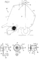
- a round baler RP according to FIG. 1 has a mobile housing 1 with an opening flap 2 and a pick-up device 3 for receiving the crop, which is wound into a round bale in a press chamber P delimited at least by press rollers 4 in the housing and thereby is compressed.
- the finished round bale is integrated into a binding net (net N) and ejected.
- a net binding device B is provided on the round baler RP (optionally together with a twine binding device; not shown).
- the binding device B is located in the region of a feed gap (not shown) to the press chamber P and is indicated schematically in FIG. 1 with a roll 5 of the network N.
- the net N coming from the roller 5 is brought in Fig. 2 by a drivable feed roller W, against which a spring-loaded counter roller 6 rests via a lever 14 and a spring 15, brought to the, preferably structured, circumference of the press roller 4, which runs counterclockwise is driven and the supplied net N applies to the round bales touching the press rolls 4, not shown, so that it takes the net N with it when it rotates and integrates itself.
- a predetermined feed length of the binding net N is then unwound before the net N is cut off with a net separator (fly knife 8, stationary anvil 7).
- the percussion knife 8 is seated on curved knife levers 9 which are pivotally mounted on a knife lever shaft 10 and, e.g. Via a knee joint mechanism 11 and a tension spring 12, are suddenly swiveled out of the tensioned standby position shown as soon as a locking device K, which holds the knife levers 9 in the standby position shown, is brought into the release position.
- the feed roller W is rotatable on an axis of rotation 13. It can be driven to initially feed the binding net N for rotation in the conveying direction, specifically by means of a belt R, which is driven by the upper press roller 4 in FIG. 2.
- the belt R is adjustable between a slip position in which the feed roller W is not driven and a coupling position (indicated by dashed lines) in which it drives the feed roller W.
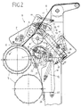
- a tensioning roller S is mounted on an actuating lever 21 which can be pivoted about a stationary axis 22.
- an actuating drive M preferably a linear motor unit, is provided which has an extendable and retractable plunger 24 which is articulated at 23 on the actuating lever 21.
- the actuator M is pivotally mounted at 25 on a support plate 29 of the binding device B, on which other components are also supported. For control and power supply, the actuator M is connected to a cable at 26.
- the locking device K for holding the knife lever 9 in the tensioned (dashed) position has at least one pawl 27 designed as a flat lever, which can be swiveled up and down about an axis 28 and is acted upon by a spring 37 in a clockwise direction.
- the pawl 27 is located behind the support plate 29, while the adjusting lever 21 is arranged in front of the support plate 29.
- a hook-like free end 31 of the pawl 27 engages behind a nose 36 arranged on at least one knife lever 9 and extends further through a cutout 30 of the support plate 29 into the range of movement of a release element 32 of the adjusting lever 21 to the front of the support plate 29
- the pawl 27 is adjusted from the illustrated blocking position, in which it engages behind the nose 36, into a release position pivoted downward in a counterclockwise direction, releasing the nose 36, by means of of the release element 32 of the actuating lever 21.
- the adjusting lever 21 is pivoted counterclockwise from the position shown by means of the actuating drive M. This pivoting has no influence on the position or movement of the pawl 27, because in the embodiment shown this is only acted upon by an additional pivoting movement of the actuating lever 21, controlled by the actuator M, from the position shown clockwise.
- a sector-shaped actuator 16 is rotatably attached, which contains an arc slot 17 which is concentric with the knife shaft 10 and into which a driver pin 18 of a return device 19 engages, expediently a hydraulic cylinder which e.g. at 20 in the support plate 29 is pivotally mounted.
- the actuating lever 21 is a Angle lever with two lever parts 21a and 21b, which are connected to each other at approximately 90 °. 4, a bearing bush 33 is attached to the lever part 21a.
- the tensioning roller S is rotatably mounted approximately in the area of the bend of the angle lever.
- the other lever part 21b is cranked and integrally formed with an approximately U-shaped side lever 34 according to FIG. 5, whose bent end 35 lying approximately parallel to the lever part 21b carries a here concave pawl control curve 32 as a release element for the pawl.
- the control cam 32 is located between the axis of the tensioning roller S and the articulation point 23 of the actuator M on the lever part 21b.
- the adjusting lever 21 is, for example, a bent part made from strip material.
- FIG. 6 illustrates the cooperation between the actuating lever 21 and the pawl 27.
- the actuating drive M is driven on the control side in such a way that it normally assumes a zero position 23 0 (FIG. 6), and from the zero position 23 0 into a coupling position 23 I or is adjustable in an end position 23 II .
- the tensioning roller S tensions the belt R in order to drive the feed roller W.
- the feed roller W is uncoupled.
- the pawl 27 is in the locked position, in which it engages behind the nose 36.
- the actuator M moves from the zero position 23 0 to the end position 23 II , the pawl 27 is moved by means of the control cam 32 from the locked position into a release position (not shown), in which it slides from the nose 36, and the movement of the knife lever 9 to disconnect the network.
- the actuator M can also be calibrated on the control side in order to find the predetermined positions exactly during the next operation.
- the actuating drive M moves the articulation point 23 into the zero position 23 0 , so that the pawl 27 is released and when the knife lever 9 is later tensioned under the force of the spring 37 behind the nose 36 jumps.
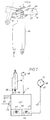
- the control device C is electronic and is preferably designed with a microprocessor MP.
- W are rotary position sensors on the feed roller 38 are provided, which are scanned by means of a resolver 39, which transmits signals representing the extent of the rotary movement of the feed roller W via a line 47 to a feed length measuring device 42 in the control device C.
- An adjusting element 43 is used to adjust the feed length.
- a timing circuit 40 is provided in the control device C, which is adjustable via an adjusting member 41 and determines the time during which the tensioning roller S tensions the belt R. This time is expediently chosen so that the free end of the network N is reliably forced to be carried along by the bale.
- a switch 44 is also provided, for example on the control device C or at a suitable point on the round baler RP and / or in the towing vehicle.
- Further signal lines 45 can supply signals to the control device C about the bale pressure representing the completion of the round bale, an opening stroke of the ejection flaps, the stopping of the round baler RP for a binding process and the correct functioning of the binding device B or / and other important information.
- the actuator M is connected to the control device C via lines 46.
- the adjusting members 41 and 43 can either be provided on the control device C, the round baler RP or in the associated towing vehicle.
- the feed roller W conveys the network N to the press roller 4, so that it reaches the press chamber P with it.
- the inclusion of the Rotary movement of the feed roller W can be registered via the resolver 39.
- the actuator M holds the tensioning roller S over the period of time set in the timer circuit 4 in the coupling position 23 I until it is certain that the net N is properly carried along by the bale. After the set time period, the actuator M is reset to the zero position 23 0 .
- the feed length measuring device 42 begins or has started to measure the feed length, based on the rotation signals of the feed roller W.
- the control device C transmits a further control signal to the actuator M, which is adjusted from its zero position 23 0 in the direction of the end position 23 II , and thereby moves the pawl 27 away from the nose 36 into the release position via the adjusting lever 21 and the control cam 32.
- the spring 12 pulls the knife lever 9 clockwise against the anvil 7 via the knee joint mechanism 11, so that the net separator disconnects the net N.
- the actuator M has meanwhile returned from the end position 23 II to the zero position 23 0 , so that the pawl 27 is ready to catch the nose 36 under the force of the spring 37.
- the return device 19 or a control valve assigned to it can also be controlled via the control device C, so that the return device 19 rotates the knife shaft 10 counterclockwise via the actuator 16 and pivots the knife lever 9 so that the spring 12 is tensioned until the pawl 27 falls behind nose 36. Then the pressure of the return device 19 is released, so that it returns to the position shown in FIG. 2.
- the binding device B is ready for a new binding process.
- the feed length could also be tapped at another element that moves with the fed network N.
- the actuator M could also engage the pawl 27 in a different way, and not indirectly by means of the actuating lever 21.
- the recuperator 19 could also tension the knife levers 9 when the actuator 16 is installed in the reverse position.
- FIG. 7 shows a device 48 guided by the control device C, which moves the pawl into the release position as soon as a predetermined length of the net N has been wrapped around the round bale.
- the device 48 is activated in that the actuator M has coupled the feed roller W to the position 23 I with an adjustment stroke.
- the drawn-off length of the network is then measured via the components 38, 39 and the device 48 finally actuates the pawl 27 as soon as the desired length has been reached.
- the actuator M does not need to perform the adjustment stroke to 23 II .
Landscapes
- Life Sciences & Earth Sciences (AREA)
- Environmental Sciences (AREA)
- Basic Packing Technique (AREA)
- Storage Of Harvested Produce (AREA)
- Toys (AREA)
- Finger-Pressure Massage (AREA)
- Food-Manufacturing Devices (AREA)
Applications Claiming Priority (2)
| Application Number | Priority Date | Filing Date | Title |
|---|---|---|---|
| DE29609555U | 1996-05-29 | ||
| DE29609555U DE29609555U1 (de) | 1996-05-29 | 1996-05-29 | Rundballenpresse |
Publications (2)
| Publication Number | Publication Date |
|---|---|
| EP0809930A1 true EP0809930A1 (fr) | 1997-12-03 |
| EP0809930B1 EP0809930B1 (fr) | 2001-08-08 |
Family
ID=8024540
Family Applications (1)
| Application Number | Title | Priority Date | Filing Date |
|---|---|---|---|
| EP97107967A Expired - Lifetime EP0809930B1 (fr) | 1996-05-29 | 1997-05-15 | Presse à balles rondes |
Country Status (2)
| Country | Link |
|---|---|
| EP (1) | EP0809930B1 (fr) |
| DE (2) | DE29609555U1 (fr) |
Cited By (3)
| Publication number | Priority date | Publication date | Assignee | Title |
|---|---|---|---|---|
| CN107278532A (zh) * | 2017-06-16 | 2017-10-24 | 安徽新安机械制造有限公司 | 一种圆捆机草捆密度自动调节装置及调节方法 |
| US10375893B2 (en) | 2013-05-27 | 2019-08-13 | Cnh Industrial America Llc | Bale wrapping mechanism |
| US11214393B2 (en) | 2017-05-07 | 2022-01-04 | CNH Industrial America, LLC | Net knife assembly |
Families Citing this family (2)
| Publication number | Priority date | Publication date | Assignee | Title |
|---|---|---|---|---|
| DE19626525C1 (de) * | 1996-07-02 | 1997-12-11 | Krone Bernhard Gmbh Maschf | Rundballenpresse |
| DE102005055375B4 (de) * | 2005-11-17 | 2007-12-20 | Usines Claas France S.A.S., St. Rémy-Woippy | Rundballenpresse |
Citations (6)
| Publication number | Priority date | Publication date | Assignee | Title |
|---|---|---|---|---|
| EP0225398A1 (fr) * | 1985-11-12 | 1987-06-16 | Ford New Holland N.V. | Presse-balles agricole |
| EP0293025A1 (fr) * | 1987-05-01 | 1988-11-30 | FORD NEW HOLLAND, INC. (a Delaware corp.) | Système de coupe pour distributeur de filet |
| US5109652A (en) * | 1989-12-27 | 1992-05-05 | Deere & Company | Indicator system for alerting an operator to the condition of a large cylindrical bale wrapping mechanism |
| US5129208A (en) * | 1990-09-05 | 1992-07-14 | Vermeer Manufacturing Company | Apparatus for feeding wrap material into a bale-forming chamber for wrapping a large round bale |
| US5216873A (en) * | 1991-10-07 | 1993-06-08 | Hay & Forage Industries | Wrapper cutoff mechanism for round balers |
| US5433059A (en) * | 1993-04-27 | 1995-07-18 | Agco Corporation | Round bale wrapping |
-
1996
- 1996-05-29 DE DE29609555U patent/DE29609555U1/de not_active Expired - Lifetime
-
1997
- 1997-05-15 DE DE59704222T patent/DE59704222D1/de not_active Expired - Fee Related
- 1997-05-15 EP EP97107967A patent/EP0809930B1/fr not_active Expired - Lifetime
Patent Citations (6)
| Publication number | Priority date | Publication date | Assignee | Title |
|---|---|---|---|---|
| EP0225398A1 (fr) * | 1985-11-12 | 1987-06-16 | Ford New Holland N.V. | Presse-balles agricole |
| EP0293025A1 (fr) * | 1987-05-01 | 1988-11-30 | FORD NEW HOLLAND, INC. (a Delaware corp.) | Système de coupe pour distributeur de filet |
| US5109652A (en) * | 1989-12-27 | 1992-05-05 | Deere & Company | Indicator system for alerting an operator to the condition of a large cylindrical bale wrapping mechanism |
| US5129208A (en) * | 1990-09-05 | 1992-07-14 | Vermeer Manufacturing Company | Apparatus for feeding wrap material into a bale-forming chamber for wrapping a large round bale |
| US5216873A (en) * | 1991-10-07 | 1993-06-08 | Hay & Forage Industries | Wrapper cutoff mechanism for round balers |
| US5433059A (en) * | 1993-04-27 | 1995-07-18 | Agco Corporation | Round bale wrapping |
Cited By (4)
| Publication number | Priority date | Publication date | Assignee | Title |
|---|---|---|---|---|
| US10375893B2 (en) | 2013-05-27 | 2019-08-13 | Cnh Industrial America Llc | Bale wrapping mechanism |
| US11214393B2 (en) | 2017-05-07 | 2022-01-04 | CNH Industrial America, LLC | Net knife assembly |
| CN107278532A (zh) * | 2017-06-16 | 2017-10-24 | 安徽新安机械制造有限公司 | 一种圆捆机草捆密度自动调节装置及调节方法 |
| CN107278532B (zh) * | 2017-06-16 | 2023-05-16 | 安徽省庐伟铝业有限公司 | 一种圆捆机草捆密度自动调节装置及调节方法 |
Also Published As
| Publication number | Publication date |
|---|---|
| DE59704222D1 (de) | 2001-09-13 |
| EP0809930B1 (fr) | 2001-08-08 |
| DE29609555U1 (de) | 1996-08-22 |
Similar Documents
| Publication | Publication Date | Title |
|---|---|---|
| DE3322024C1 (de) | Umhuellungsvorrichtung fuer Rundballen in Ballenpressen | |
| DE68911392T2 (de) | Rundballenpresse. | |
| DE3418681C2 (fr) | ||
| EP2296518B1 (fr) | Distributeur de papier | |
| DE4442479C2 (de) | Überwachungs- und Steuersystem für Ballenpressen | |
| EP1461995A2 (fr) | Dispositif d'emballage d'une balle avec une enveloppe, presse a balles et détecteur | |
| DE102019205325A1 (de) | Ballenwickelvorrichtung für eine Ballenpresse, Beladehilfe und Ballenpresse | |
| DE2719018A1 (de) | Vorrichtung zur zufuehrung von dokumenten | |
| EP1991464A1 (fr) | Dispotif puor serrer une bande | |
| EP0809930B1 (fr) | Presse à balles rondes | |
| EP2042027B1 (fr) | Presse à ballots ronds | |
| DE69801615T2 (de) | Sicherheitsvorrichtung für eine Nadelauslöseeinrichtung | |
| EP1284594B1 (fr) | Ramasseur pour presse a piston | |
| DE102005055375B4 (de) | Rundballenpresse | |
| DE3878311T2 (de) | Schneidvorrichtung fuer netzgewebespender. | |
| EP0998845B1 (fr) | Dispositif d'actionnement de l'embrayage du dispositif de liage d'une presse à grandes balles | |
| EP1454521B1 (fr) | Dispositif pour envelopper des balles et presse à balles | |
| EP1059024A1 (fr) | Presse à balles rondes pour produits agricoles | |
| DE102023124111A1 (de) | Rundballenpresse | |
| EP3391733B1 (fr) | Presse à balles | |
| EP3391729B1 (fr) | Presse à balles | |
| EP3391734B1 (fr) | Presse à balles | |
| EP0815719B1 (fr) | Presse à balles rondes | |
| DE69517859T2 (de) | Bindegarn-Schneidvorrichtung für eine Rundballenpresse | |
| DE3432251A1 (de) | Rundballenpresse fuer landwirtschaftliches erntegut |
Legal Events
| Date | Code | Title | Description |
|---|---|---|---|
| PUAI | Public reference made under article 153(3) epc to a published international application that has entered the european phase |
Free format text: ORIGINAL CODE: 0009012 |
|
| AK | Designated contracting states |
Kind code of ref document: A1 Designated state(s): BE DE FR GB NL |
|
| 17P | Request for examination filed |
Effective date: 19980109 |
|
| GRAG | Despatch of communication of intention to grant |
Free format text: ORIGINAL CODE: EPIDOS AGRA |
|
| 17Q | First examination report despatched |
Effective date: 20000517 |
|
| GRAG | Despatch of communication of intention to grant |
Free format text: ORIGINAL CODE: EPIDOS AGRA |
|
| GRAH | Despatch of communication of intention to grant a patent |
Free format text: ORIGINAL CODE: EPIDOS IGRA |
|
| GRAH | Despatch of communication of intention to grant a patent |
Free format text: ORIGINAL CODE: EPIDOS IGRA |
|
| GRAA | (expected) grant |
Free format text: ORIGINAL CODE: 0009210 |
|
| AK | Designated contracting states |
Kind code of ref document: B1 Designated state(s): BE DE FR GB NL |
|
| PG25 | Lapsed in a contracting state [announced via postgrant information from national office to epo] |
Ref country code: NL Free format text: LAPSE BECAUSE OF FAILURE TO SUBMIT A TRANSLATION OF THE DESCRIPTION OR TO PAY THE FEE WITHIN THE PRESCRIBED TIME-LIMIT Effective date: 20010808 Ref country code: GB Free format text: LAPSE BECAUSE OF FAILURE TO SUBMIT A TRANSLATION OF THE DESCRIPTION OR TO PAY THE FEE WITHIN THE PRESCRIBED TIME-LIMIT Effective date: 20010808 |
|
| REF | Corresponds to: |
Ref document number: 59704222 Country of ref document: DE Date of ref document: 20010913 |
|
| NLV1 | Nl: lapsed or annulled due to failure to fulfill the requirements of art. 29p and 29m of the patents act | ||
| ET | Fr: translation filed | ||
| GBV | Gb: ep patent (uk) treated as always having been void in accordance with gb section 77(7)/1977 [no translation filed] |
Effective date: 20010808 |
|
| PG25 | Lapsed in a contracting state [announced via postgrant information from national office to epo] |
Ref country code: BE Free format text: LAPSE BECAUSE OF NON-PAYMENT OF DUE FEES Effective date: 20020531 |
|
| PLBE | No opposition filed within time limit |
Free format text: ORIGINAL CODE: 0009261 |
|
| STAA | Information on the status of an ep patent application or granted ep patent |
Free format text: STATUS: NO OPPOSITION FILED WITHIN TIME LIMIT |
|
| 26N | No opposition filed | ||
| PGFP | Annual fee paid to national office [announced via postgrant information from national office to epo] |
Ref country code: DE Payment date: 20040629 Year of fee payment: 8 |
|
| PG25 | Lapsed in a contracting state [announced via postgrant information from national office to epo] |
Ref country code: DE Free format text: LAPSE BECAUSE OF NON-PAYMENT OF DUE FEES Effective date: 20051201 |
|
| REG | Reference to a national code |
Ref country code: FR Ref legal event code: TP Ref country code: FR Ref legal event code: CD |
|
| REG | Reference to a national code |
Ref country code: FR Ref legal event code: CD |
|
| REG | Reference to a national code |
Ref country code: FR Ref legal event code: PLFP Year of fee payment: 20 |
|
| PGFP | Annual fee paid to national office [announced via postgrant information from national office to epo] |
Ref country code: FR Payment date: 20160422 Year of fee payment: 20 |