EP0809540B1 - Procede de fabrication d'elements de fixation et element relatif - Google Patents
Procede de fabrication d'elements de fixation et element relatif Download PDFInfo
- Publication number
- EP0809540B1 EP0809540B1 EP96903763A EP96903763A EP0809540B1 EP 0809540 B1 EP0809540 B1 EP 0809540B1 EP 96903763 A EP96903763 A EP 96903763A EP 96903763 A EP96903763 A EP 96903763A EP 0809540 B1 EP0809540 B1 EP 0809540B1
- Authority
- EP
- European Patent Office
- Prior art keywords
- fastening element
- fastener
- spindle
- shank portion
- parts
- Prior art date
- Legal status (The legal status is an assumption and is not a legal conclusion. Google has not performed a legal analysis and makes no representation as to the accuracy of the status listed.)
- Expired - Lifetime
Links
- 238000000034 method Methods 0.000 title claims description 38
- 239000000463 material Substances 0.000 claims description 81
- 239000011344 liquid material Substances 0.000 claims description 19
- 239000004952 Polyamide Substances 0.000 claims description 7
- 229920002647 polyamide Polymers 0.000 claims description 7
- 238000001816 cooling Methods 0.000 claims description 6
- 239000012943 hotmelt Substances 0.000 claims description 5
- 239000002184 metal Substances 0.000 claims description 5
- 229910052751 metal Inorganic materials 0.000 claims description 5
- 238000010438 heat treatment Methods 0.000 claims description 3
- 229920001187 thermosetting polymer Polymers 0.000 claims description 3
- 239000000110 cooling liquid Substances 0.000 claims 1
- 238000003303 reheating Methods 0.000 claims 1
- 239000011324 bead Substances 0.000 description 11
- 238000009434 installation Methods 0.000 description 5
- XLYOFNOQVPJJNP-UHFFFAOYSA-N water Substances O XLYOFNOQVPJJNP-UHFFFAOYSA-N 0.000 description 5
- 239000011248 coating agent Substances 0.000 description 4
- 238000000576 coating method Methods 0.000 description 4
- 238000004806 packaging method and process Methods 0.000 description 4
- 230000000694 effects Effects 0.000 description 3
- 230000005484 gravity Effects 0.000 description 3
- 239000007788 liquid Substances 0.000 description 3
- 238000004519 manufacturing process Methods 0.000 description 3
- 230000003287 optical effect Effects 0.000 description 3
- 230000000717 retained effect Effects 0.000 description 3
- 238000004026 adhesive bonding Methods 0.000 description 2
- 238000000151 deposition Methods 0.000 description 2
- 230000009969 flowable effect Effects 0.000 description 2
- 230000006698 induction Effects 0.000 description 2
- 238000005304 joining Methods 0.000 description 2
- 230000014759 maintenance of location Effects 0.000 description 2
- 239000012768 molten material Substances 0.000 description 2
- 239000004033 plastic Substances 0.000 description 2
- 238000010791 quenching Methods 0.000 description 2
- 229920001169 thermoplastic Polymers 0.000 description 2
- 239000012815 thermoplastic material Substances 0.000 description 2
- 239000004416 thermosoftening plastic Substances 0.000 description 2
- 238000003466 welding Methods 0.000 description 2
- OKTJSMMVPCPJKN-UHFFFAOYSA-N Carbon Chemical compound [C] OKTJSMMVPCPJKN-UHFFFAOYSA-N 0.000 description 1
- 239000004677 Nylon Substances 0.000 description 1
- 239000004743 Polypropylene Substances 0.000 description 1
- 239000004809 Teflon Substances 0.000 description 1
- 229920006362 Teflon® Polymers 0.000 description 1
- 239000002253 acid Substances 0.000 description 1
- 150000007513 acids Chemical class 0.000 description 1
- 150000001298 alcohols Chemical class 0.000 description 1
- 238000007664 blowing Methods 0.000 description 1
- 239000004927 clay Substances 0.000 description 1
- 229910052570 clay Inorganic materials 0.000 description 1
- 238000004891 communication Methods 0.000 description 1
- 238000010276 construction Methods 0.000 description 1
- 239000002826 coolant Substances 0.000 description 1
- 239000012809 cooling fluid Substances 0.000 description 1
- 239000000945 filler Substances 0.000 description 1
- 238000010304 firing Methods 0.000 description 1
- 239000012530 fluid Substances 0.000 description 1
- 239000000446 fuel Substances 0.000 description 1
- 239000011521 glass Substances 0.000 description 1
- 239000010439 graphite Substances 0.000 description 1
- 229910002804 graphite Inorganic materials 0.000 description 1
- 238000010348 incorporation Methods 0.000 description 1
- 230000001788 irregular Effects 0.000 description 1
- 150000002576 ketones Chemical class 0.000 description 1
- 230000001050 lubricating effect Effects 0.000 description 1
- 230000000873 masking effect Effects 0.000 description 1
- 230000013011 mating Effects 0.000 description 1
- 239000000155 melt Substances 0.000 description 1
- 150000002739 metals Chemical class 0.000 description 1
- 239000003595 mist Substances 0.000 description 1
- 229920001778 nylon Polymers 0.000 description 1
- 239000003921 oil Substances 0.000 description 1
- -1 polypropylene Polymers 0.000 description 1
- 229920001155 polypropylene Polymers 0.000 description 1
- 238000002360 preparation method Methods 0.000 description 1
- 239000010703 silicon Substances 0.000 description 1
- 229910052710 silicon Inorganic materials 0.000 description 1
- 238000009987 spinning Methods 0.000 description 1
- 239000000126 substance Substances 0.000 description 1
- 239000000758 substrate Substances 0.000 description 1
Images

Classifications
-
- B—PERFORMING OPERATIONS; TRANSPORTING
- B05—SPRAYING OR ATOMISING IN GENERAL; APPLYING FLUENT MATERIALS TO SURFACES, IN GENERAL
- B05C—APPARATUS FOR APPLYING FLUENT MATERIALS TO SURFACES, IN GENERAL
- B05C11/00—Component parts, details or accessories not specifically provided for in groups B05C1/00 - B05C9/00
- B05C11/10—Storage, supply or control of liquid or other fluent material; Recovery of excess liquid or other fluent material
- B05C11/1002—Means for controlling supply, i.e. flow or pressure, of liquid or other fluent material to the applying apparatus, e.g. valves
- B05C11/1034—Means for controlling supply, i.e. flow or pressure, of liquid or other fluent material to the applying apparatus, e.g. valves specially designed for conducting intermittent application of small quantities, e.g. drops, of coating material
-
- B—PERFORMING OPERATIONS; TRANSPORTING
- B05—SPRAYING OR ATOMISING IN GENERAL; APPLYING FLUENT MATERIALS TO SURFACES, IN GENERAL
- B05C—APPARATUS FOR APPLYING FLUENT MATERIALS TO SURFACES, IN GENERAL
- B05C11/00—Component parts, details or accessories not specifically provided for in groups B05C1/00 - B05C9/00
- B05C11/10—Storage, supply or control of liquid or other fluent material; Recovery of excess liquid or other fluent material
-
- B—PERFORMING OPERATIONS; TRANSPORTING
- B05—SPRAYING OR ATOMISING IN GENERAL; APPLYING FLUENT MATERIALS TO SURFACES, IN GENERAL
- B05C—APPARATUS FOR APPLYING FLUENT MATERIALS TO SURFACES, IN GENERAL
- B05C13/00—Means for manipulating or holding work, e.g. for separate articles
-
- B—PERFORMING OPERATIONS; TRANSPORTING
- B05—SPRAYING OR ATOMISING IN GENERAL; APPLYING FLUENT MATERIALS TO SURFACES, IN GENERAL
- B05C—APPARATUS FOR APPLYING FLUENT MATERIALS TO SURFACES, IN GENERAL
- B05C5/00—Apparatus in which liquid or other fluent material is projected, poured or allowed to flow on to the surface of the work
- B05C5/02—Apparatus in which liquid or other fluent material is projected, poured or allowed to flow on to the surface of the work the liquid or other fluent material being discharged through an outlet orifice by pressure, e.g. from an outlet device in contact or almost in contact, with the work
- B05C5/0208—Apparatus in which liquid or other fluent material is projected, poured or allowed to flow on to the surface of the work the liquid or other fluent material being discharged through an outlet orifice by pressure, e.g. from an outlet device in contact or almost in contact, with the work for applying liquid or other fluent material to separate articles
- B05C5/0212—Apparatus in which liquid or other fluent material is projected, poured or allowed to flow on to the surface of the work the liquid or other fluent material being discharged through an outlet orifice by pressure, e.g. from an outlet device in contact or almost in contact, with the work for applying liquid or other fluent material to separate articles only at particular parts of the articles
-
- B—PERFORMING OPERATIONS; TRANSPORTING
- B05—SPRAYING OR ATOMISING IN GENERAL; APPLYING FLUENT MATERIALS TO SURFACES, IN GENERAL
- B05D—PROCESSES FOR APPLYING FLUENT MATERIALS TO SURFACES, IN GENERAL
- B05D1/00—Processes for applying liquids or other fluent materials
- B05D1/002—Processes for applying liquids or other fluent materials the substrate being rotated
-
- F—MECHANICAL ENGINEERING; LIGHTING; HEATING; WEAPONS; BLASTING
- F16—ENGINEERING ELEMENTS AND UNITS; GENERAL MEASURES FOR PRODUCING AND MAINTAINING EFFECTIVE FUNCTIONING OF MACHINES OR INSTALLATIONS; THERMAL INSULATION IN GENERAL
- F16B—DEVICES FOR FASTENING OR SECURING CONSTRUCTIONAL ELEMENTS OR MACHINE PARTS TOGETHER, e.g. NAILS, BOLTS, CIRCLIPS, CLAMPS, CLIPS OR WEDGES; JOINTS OR JOINTING
- F16B39/00—Locking of screws, bolts or nuts
- F16B39/22—Locking of screws, bolts or nuts in which the locking takes place during screwing down or tightening
- F16B39/28—Locking of screws, bolts or nuts in which the locking takes place during screwing down or tightening by special members on, or shape of, the nut or bolt
- F16B39/34—Locking by deformable inserts or like parts
-
- F—MECHANICAL ENGINEERING; LIGHTING; HEATING; WEAPONS; BLASTING
- F16—ENGINEERING ELEMENTS AND UNITS; GENERAL MEASURES FOR PRODUCING AND MAINTAINING EFFECTIVE FUNCTIONING OF MACHINES OR INSTALLATIONS; THERMAL INSULATION IN GENERAL
- F16B—DEVICES FOR FASTENING OR SECURING CONSTRUCTIONAL ELEMENTS OR MACHINE PARTS TOGETHER, e.g. NAILS, BOLTS, CIRCLIPS, CLAMPS, CLIPS OR WEDGES; JOINTS OR JOINTING
- F16B41/00—Measures against loss of bolts, nuts, or pins; Measures against unauthorised operation of bolts, nuts or pins
- F16B41/002—Measures against loss of bolts, nuts or pins
-
- B—PERFORMING OPERATIONS; TRANSPORTING
- B05—SPRAYING OR ATOMISING IN GENERAL; APPLYING FLUENT MATERIALS TO SURFACES, IN GENERAL
- B05D—PROCESSES FOR APPLYING FLUENT MATERIALS TO SURFACES, IN GENERAL
- B05D2258/00—Small objects (e.g. screws)
- B05D2258/02—The objects being coated one after the other
-
- F—MECHANICAL ENGINEERING; LIGHTING; HEATING; WEAPONS; BLASTING
- F16—ENGINEERING ELEMENTS AND UNITS; GENERAL MEASURES FOR PRODUCING AND MAINTAINING EFFECTIVE FUNCTIONING OF MACHINES OR INSTALLATIONS; THERMAL INSULATION IN GENERAL
- F16B—DEVICES FOR FASTENING OR SECURING CONSTRUCTIONAL ELEMENTS OR MACHINE PARTS TOGETHER, e.g. NAILS, BOLTS, CIRCLIPS, CLAMPS, CLIPS OR WEDGES; JOINTS OR JOINTING
- F16B11/00—Connecting constructional elements or machine parts by sticking or pressing them together, e.g. cold pressure welding
- F16B11/006—Connecting constructional elements or machine parts by sticking or pressing them together, e.g. cold pressure welding by gluing
-
- Y—GENERAL TAGGING OF NEW TECHNOLOGICAL DEVELOPMENTS; GENERAL TAGGING OF CROSS-SECTIONAL TECHNOLOGIES SPANNING OVER SEVERAL SECTIONS OF THE IPC; TECHNICAL SUBJECTS COVERED BY FORMER USPC CROSS-REFERENCE ART COLLECTIONS [XRACs] AND DIGESTS
- Y10—TECHNICAL SUBJECTS COVERED BY FORMER USPC
- Y10S—TECHNICAL SUBJECTS COVERED BY FORMER USPC CROSS-REFERENCE ART COLLECTIONS [XRACs] AND DIGESTS
- Y10S411/00—Expanded, threaded, driven, headed, tool-deformed, or locked-threaded fastener
- Y10S411/904—Fastener or fastener element composed of nonmetallic material
- Y10S411/908—Resinous material
Definitions
- the present invention relates to the application of a deposit of material to a succession of discrete articles. More particularly, the present invention relates to a method and apparatus for depositing a droplet or an extended bead of thermoplastic or thermoset material onto the surface of a metal or plastic part.
- the flexible compressible bead extends above the surface of the part in order to create assembly resistance when the part is assembled into or over another part. This resistance serves to temporarily secure the location of the respective parts one to another prior to more permanent joining by welding, gluing or threaded torquing.
- brackets made from metal stampings which are attached to vehicles by several screws.
- the brackets and screws are currently shipped separately to the assembly plant under separate part numbers. Once they arrive at the installation facility, they must be coupled prior to installation. As a result, significant additional time and labor costs are incurred to combine the brackets and screws once they arrive at the installation plant. There is always the danger that one or more of the screws may fall out of the assembly prior to ultimate installation or through human error fail to initially be inserted in the appropriate place.
- United States Patent No. 4,851,175 to Wallace discloses a method of making O-rings by supplying a continuous stream of liquid hot melt material under the force of gravity alone onto a rotating spindle or directly upon the shank of the rotating fastener.
- This method is capable of forming only a continuous O-ring around the outer circumference of the fastener and generally uses a heater such as a flame jet spaced from a falling filament of material to soften the deposit on each fastener to cause it to flow into a more conforming state as required such as a flatter wider band.
- this prior art method contemplates a continuous filament of hot liquid material falling from a nozzle that is not capable of precisely locating a dot of such material on only a portion of the outer circumference of such fasteners.
- this method is only effective in producing o-rings that cover the entire 360° circumference of a portion of a fastener.
- Such an O-ring is usually intended to effect the final assembly of parts by acting as a seal or the like.
- Such an O-ring would be insufficient in many instances to provide a deposit of material that is tough enough to resist part disassembly, but does not interfere with or alter the final assembly of the parts.
- This prior art method likewise does not provide for discontinuous flow of material that only activates in the presence of a fastener.
- thermoplastic material for example, in U.S. Patent No. Re 33,766 to Duffy et al.
- This method applies a masking insulating or lubricating coating of teflon or similar material to all or a portion of the threads of the coating.
- the coating produced by this method does not extend far enough above the surface of the fastener or have sufficient retaining ability in order to serve as a retaining element for a second part. Both of these above described methods produce materials that tend to closely follow the contours of the threads of the fastener when applied and also interfere with the ultimate assembly of the parts.
- the present invention further contemplates a method of forming more than one retaining element either of the same or different types on a single fastener or other discrete article and fasteners with such retaining elements applied thereto.
- U.S. Patent No. 3991704 describes a system for forming a band of coating material around the threaded shanks of a plurality of headed fasteners.
- the band is, however, intended to help to form a tight interlocking arrangement when the article is inserted into a corresponding threaded member.
- the invention provides a method of forming a deposit on a first fastening element comprising the steps of providing a spindle, rotatably supporting said spindle, removably attaching the first fastening element to said spindle, rotating said spindle with said first fastening element attached thereto, sensing whether said first fastening element is present, applying a discrete shot of molten liquid material onto a preselected portion of the surface of said first fastening element if said first fastening element is sensed in said sensing step, characterised in that the method further comprises heating said first fastening element prior to said sensing step, the preselected portion being of the heated surface of said first fastening element, and in that the liquid material is applied with the first fastening element removably attached to said spindle, the method including continuing to rotate said spindle and said first fastening element with said liquid material thereon at a speed that generates centrifugal force sufficient to move a portion of said molten liquid material outwardly away from the
- the invention also provides a fastener comprising a head portion at one end of the fastener, a shank portion connected to the head portion and an element located along the shank portion of the fastener comprising a deposit of material adhered to the shank portion, characterised in that the element is a retaining element extending sufficiently above a surface of the shank portion so as to temporarily retain a second fastener along the shank portion of the first fastener between the retaining element and the head portion of the first fastener.
- the present invention provides a method for applying deposits of material around a portion or all of the circumference of discrete articles such as fasteners so that the material extends above the surface of the part to create assembly resistance serving to temporarily secure the location of the part one to another prior to more permanent joining by welding, gluing or threaded torquing of the entire assembly.
- Yet another object of the present invention is to provide a flexible compressible deposit of material that projects above the surface of a fastener or shaft that assists in temporarily securing another part to the fastener shaft, but does not alter or interfere with the final assembly of the parts.
- Still another object of the present invention is to provide a flexible compressible deposit of material on a portion of a fastener of a preselected shape and height that is related to the speed of rotation of the fastener during application.
- a method of making retaining elements on parts comprising the steps of providing a spindle, supporting the spindle in a manner such that the spindle is capable of rotation, removably attaching a part to the spindle, rotating the spindle with the part attached thereto, heating the part, sensing whether a part is present on the spindle, supplying a discrete shot of molten liquid material that solidifies upon cooling onto a preselected portion of the part if the part is sensed in the sensing steps, and continuing to rotate the spindle after the material has been supplied in the supplying step at a speed capable of generating centrifugal force sufficient to urge the molten liquid material supplied in the supplying step to extend substantially above the surface of the part when it solidifies.
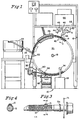
- the apparatus 10 there illustrated comprises a wheel 20 in the form of a circular disc which is mounted for rotation and a vertical plane about its central axis on a horizontal shaft 18 to which it is affixed.
- the shaft 18 is rotatably mounted in bearing blocks 17 on the frame 16.
- the wheel 20 has a plurality of parts holding pins 40 near its outer edge.
- the pins 40 are preferably arranged in equally spaced relation in a circle concentric with the axis of rotation of the wheel 20. Bearings support each pin 40 for axial rotation.
- the pins 40 extend at substantially right angles to the plane of the wheel 20 and are therefore horizontal and present a substantially flat end surface to attach parts 12 thereto.
- a variable speed motor 30 mounted on a stand 72 drives the wheel 20 by means of a chain 52 extending around a sprocket 54 on the output shaft of the motor 30 and also a sprocket 60 on the shaft 18.
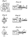
- the pins 40 can be magnetized in order to retain the parts 12 during the processing operation or they could be provided with removable mechanical attachment elements 84a, 84b and 84c, such as illustrated in Figures 9-13 respectively.
- These attachment elements 84a, 84b and 84c are adapted to slip fit over the pins and provide mechanical attachment of threaded elements such as 90, 91 or 92 and non-threaded elements alike.
- the exemplary elements illustrated in Figures 9-13 demonstrate that through their use a wide variety of parts having regular or irregular shapes, configurations and/or end surfaces can be processed by the present invention.
- each pin 40 has a sprocket 60 located along its length that extends outwardly beyond a portion of the outer surface of its construction.
- An endless chain 38 extends around the wheel 20 in engagement with a number of the sprockets 60 and is driven by a sprocket 64 on the output shaft of a variable speed motor 62 carried by the frame 16.
- a sprocket 64 on the output shaft of a variable speed motor 62 carried by the frame 16.
- a reservoir 66 is mounted on the frame 60 above the wheel 20.
- the reservoir 66 contains a supply of heated liquid thermoplastic, thermoset, hot melt or PVC material.
- polyamide is a hot melt material that is particularly well suited for use in this invention.
- An example of such a material is polyamide #108100/HM-0904 sold by H.B. Fuller & Co. Deposits made of this material are particularly preferred since they exhibit improved temperature and chemical resistance over materials such as amorphous polypropylene.
- Polyamides are flowable under pressure and have no or minimal elastic qualities such that once it is used it normally cannot be reused. They are tough yet deformable, it has no "cure” feature or requirement. They are available in several grades from softer to harder and is insoluble in all common fuels including ketones, alcohols, oils (natural and synthetic) and dilute acids. Such materials are heat flowable. When cooled to room temperature they show almost no deposit to deposit tack making them ideal for the bulk handling of parts to which the material 14 is applied. Numerous fillers can be added to the hot melt material particulates ranging from powdered nylon, glass, silicon, clay, graphite or metals can be used for various effects. As particularly illustrated in Figures 1 and 2, the reservoir 66 is connected to a support 68 attached to frame 16.
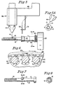
- each gun 46 utilized is provided with a stage 48 that serves to secure and support the gun 46.
- the stage 48 is important to the precision of the ultimate delivery of material 14 from the gun 46 since it allows the adjustment of the gun 46 in up to three different distinct axes.
- Stage 48 also permits an attachment means that enables rotational movement of the gun 46 about its point of attachment.
- Many different known stages can be utilized in connection with the present invention as long as they provide for the selective adjustment of the position of the gun 46 along a number of different axes.
- a particularly suitable commercially available stage has been found to be the 4500 Series ball bearing stage manufactured by the Daedal Division of Parker Corporation of Harrison City, Pennsylvania.
- the stage 48 also provides a point of attachment for an optical sensor holder 51 that houses an optical sensor 50.
- the optical sensor 50 is directed in a manner so that it senses whether a pin 40 or a part 12 such as a fastener is present. Once a part is sensed, the sensor 50 then sends a signal causing a precisely metered shot of liquid material 14 to issue from the gun 46 only when it is indicated that a part 12 is appropriately located under the nozzle 44 of the gun 46.
- the sensor 50 is therefore in communication with the electro-pneumatic firing mechanism of the gun 46 to control the timing of the output of material 14 therefrom.
- a particularly preferred sensor for use with the present invention has been an OMRON photoelectric switch (Model E3A2-XCM4T).
- the gun 46 fires precisely timed shots or droplets of material 14 in response to an indication from the sensor 50 that a part 12 is present and properly aligned under the nozzle 44.
- the present invention can utilize either single or multiple guns 46 to deposit material 14 onto parts 12.
- a single gun 46 produces a single deposit of material 14 on each part, such as illustrated in Figure 7 for example.
- multiple guns can produce multiple deposits of material 14 in many different forms such as, for example, the deposits 15 and 15a.
- the gun 46 must be capable of precisely controlling the amount, direction and speed of each metered shot of material 14 that it deposits. Additionally, the gun 46 must also have the capability of metering a high number of discrete shots of material 14 per unit of time and provide consistent clog-free operation and efficient cut off of material flow without dripping.
- the gun 46 is heated in some manner so as to maintain additional control over the viscosity of the material 14 exited through the nozzle 44. It is preferred that the gun 46 have a maximum operating temperature of about 450°F (232.2°C) and an operating air pressure in the range of approximately 30-100psi (206.8-689.5 kN/m 2 ) or at least 60-100psi (413.7-689.5 kN/m 2 ).
- the gun should also have a working hydraulic pressure of at least 1500psi and be capable of operating at speeds exceeding 3500 cycles per minute.
- the diameter of the gun should be between .008 and .040 inches (0.020-0.102 cm).
- a commercially available gun that has been found to be particularly useful in meeting or exceeding these parameters is the Nordson H-201 gun with a zero cavity module manufactured by Nordson Corporation of Norcross, Georgia.
- the frame 16 also provides a point of attachment for a heater 26 such as illustrated in Figure 1.
- the heater 26 can take many different forms including an infrared heater or an induction heater.
- the heater serves to sufficiently increase the temperature of the parts that pass through it to a temperature sufficient to maximize the ability of the material 14 to form discrete deposits 15 that are raised above the surface of the parts 12 such as fasteners shown in Figures 3-4 and 7-14.
- the heater 26 also serves to improve the adhesion of the material 14 ultimately deposited on the parts 12.
- a rinse tank 28 Downstream from the heater 26 and gun 46, a rinse tank 28 is provided that has a reservoir of a cooling material.
- the tank 28 is connected to a rinse nozzle 34 that selectively deposits cooling fluid onto the area of the parts 12 that pass by it in order to insure that the material 14 deposited thereon is solidified prior to collection and packaging.
- a variety of cooling materials can be used, it has been found efficient in most circumstances to utilize cool air or water that is at room temperature or slightly cooled.
- a stripper 58 Located downstream of the rinse tank 28 and near the bottom of wheel 20 on one side thereof a stripper 58 is provided comprising a plate supported by a stand 59.
- the stripper 58 is provided at the angle shown in Figure 1 in relation to the parts 12 on the pins 40.
- the stripper 58 extends across the paths of the parts 12 to force the then processed parts 12 from their respective pins 40 as the rotation of the wheel 20 forces successive parts 12 into contact with the stripper 58.
- the parts 12 are removed from the pins 40 as the stripper 58 breaks either the magnetic attraction between the parts 12 and the pins 40 or the mechanical connection between the two.
- the parts 12 then fall under the force of gravity onto a finished parts conveyor 88 for ultimate packaging or for additional processing.
- other known structures and methods such as a pneumatically driven plunger could be used to strip the parts 12 from the pins 40 if additional removal force is desired.
- the apparatus 10 of the present invention is first powered up so that the motor 62 is rotating the wheel 20 in a clockwise direction in the embodiment shown in Figure 1 and so that the motor 30 is enabling rotation of each of the individual pins 40 that are in contact with the chain 38 in a clockwise direction, the same as the direction of rotation of the wheel 20.
- the motor 30 allows the speed of rotation of the pins 40 to be varied in order to affect the shape and height of the deposit 15 of material 14 on the parts 12.
- parts 12 such as fasteners are introduced to the pins 40 in a continuous spaced manner. Delivery of the parts 12 is indexed such that a single part 12 is provided to each pin 40 that passes by the point of introduction of the parts. Parts 12 can be deposited onto the pins 40 of the rotating wheel either manually or by many known parts delivery systems such as a vibratory feeder 22 connected to an angled track 24 as illustrated in Figure 1. Although not required, it has been found to be somewhat advantageous to attach parts 12 to the pins 40 before the individual sprockets 60 engage the chain 38 to begin rotation of the pins 40.
- the parts 12 are retained in position on the pins 40 either by magnetic forces or mechanical holding elements such as 84a, 84b and 84c.
- its sprocket 60 engages the chain 38 to rotate that pin 40 and then part 12 attached thereto.
- the wheel 20 continues to rotate the parts 12 toward the heater 26.
- the parts 12 first are preheated to a temperature near the melt point of the material 14 by the heater 26. This is required to insure that the material 14 will adhere well to the surface of the parts 12.
- each part 12 is shot with a single bead of viscous molten material 14 which is deposited at a selectively desired location along the length of the part 12 by the gun 46 in response to a sensor signal. Due to the adjustability of the gun 46 the material 14 can be deposited virtually anywhere along the length of the parts 12 as illustrated by example in Figures 3, 4, 7, 10, 12 and 14. As also illustrated in these figures, it is usually desired with respect to the present invention to provide an ultimate deposit 15 of material 14 on each part 12 that once applied remains projecting substantially above the surface of each part 12 and does not flow out flat on the surface of each part 12 once the material 14 contacts the part 12.
- the present invention can provide more than one discrete deposit of material 14 on a single part 12, such as deposits 15 and 15a, by using multiple guns 46 and sensors 51.
- the present invention can be utilized to form deposits that selectively extend from a small portion to the entire 360° circumference of a given part. Additionally, modifying the flow rate of the material 14 from the guns 46, and/or the speed of rotation of the parts 12, more elongated deposits or ring type deposits 15a can be formed by the present invention alone or in combination with bead type deposits 15. Also, the present invention can be used to retain a washer or other element on a part 12 by sliding the washer 71 over the part 12 prior to depositing any material 14 onto the part 12.
- the rotation speed of the pins 40 is preadjusted so that the resulting centrifugal force offsets the tendency of the then deposited liquid material 14 to flow out flat, but is not so great as to throw the liquid off of the part. Without a significant rotation speed of each of the pins 40 and therefore the parts 12 attached to them there would be little or no projection of the deposits 15 of material 14 above the part surface. If the height of the finished deposit is not great enough then insufficient retention ability results in the ultimate deposit 15 of material 14 on the part 12 which does not serve to temporarily retain the part 12 in relation to another part in contemplation of further ultimate assembly. It has been found that, in order to achieve the desired effect and produce an appropriately shaped bead type deposit 15 that projects sufficiently above the surface of the parts 12, that pin rotation speeds on the order of about 100-150 rpm are preferable.
- the parts 12 leave the area of the one or more guns 46 that are present they are then moved by the wheel 20 to allow sufficient time while they are still rotating on their individual pins 40 for the base of the deposit 15 of material 14 to wet on the parts 12 and for the deposit 15 to attain the final desired shape.
- the centrifugal force resulting from the rotation of the pins 40 and parts 12 continues to encourage the material 14 to remain upwardly extending from the surface of the parts 12 and avoid the tendency of the liquid material 14 to flow out flat.
- the parts 12 are then further cooled either with blowing air or a water quench 34 in order to further harden the material 14 deposited thereon.
- each coated part 12 next encounters the stripper 58 which breaks the connection between the individual pins 40 and the parts 12.
- the stripper 58 By the time each part 12 encounters the stripper 58, it is at times preferable to insure that the sprocket 60 of each pin 40 is still in contact with the chain 38 so that the part 12 and pin 40 are still spinning to assist in breaking the connection to remove the parts 12.
- the parts 12 Once removed, the parts 12 then fall down under the force of gravity until they encounter a conveyor belt 88 which carries them away from the area of the wheel 20. If the cooling medium used was water then an additional conveyor 31 can be provided that removes the parts 12 from the conveyor belt 88 and directs them past an off-line dryer 32 in order to dry any water that may be remaining on the parts 12 prior to ultimate packaging.
- cold headed M-14 flange bolts were deposited on successive rotating magnetic pins on a 4 foot (1.22 m) diameter wheel that had 100 parts holders or pin positions.
- the wheel was travelling at a speed such that it took approximately two and one half minutes to complete one full rotation.
- the parts were fed to the pins by a vibratory feeder bowl and track.
- the individual bolts were attached one to each successive pin and retained by the magnetic attraction of the pins.
- the pins and bolts were rotated at a rate of 130rpm as the bolts on the rotating pins were rotated by the wheel in the same direction as the rotation of the individual pins.
- the bolts were then passed through a 25 kilowatt low frequency induction heater set at 10 kilohertz or an 80 setting.
- the heaters increased the ambient temperature surrounding the bolts to 350° at the area where the bolts exited the heater.
- the bolts then were each supplied with a bead of polyamide material on a preselected portion of their length.
- the polyamide material had a viscosity of 6000cps at 400°F (204.44°C) and were metered using a single Nordson Zero Cavity Module H-201 gun.
- This cooling process cooled the fasteners to approximately 120°F (48.89°C). Once the fasteners left the cooling area they were stripped and dropped onto a conveyor belt for ultimate packaging.
- the bolts that were processed had a bead of material of the size and type illustrated in Figures 7-8.
- the deposited bead of material extended a sufficient distance above the surface of the bolts so as to be acceptable in shape to retain another part in place pending ultimate assembly and the circumferential extent of the material did not extend beyond an acceptable region.
- the polyamide material on the bolts was then tested for a pull off force and results indicated that they would withstand a 201b (88.96 N) pull off force. From this example it is clear that the present invention was demonstrated to produce very effective desired results.
Landscapes
- Engineering & Computer Science (AREA)
- General Engineering & Computer Science (AREA)
- Mechanical Engineering (AREA)
- Coating Apparatus (AREA)
- Slide Fasteners, Snap Fasteners, And Hook Fasteners (AREA)
Claims (25)
- Procédé de formation d'un dépôt sur un premier élément de fixation (12, 90, 91, 92) comportant les étapes suivantes : la fourniture d'une broche (40), le support rotatif de ladite broche, la fixation amovible du premier élément de fixation (12, 90, 91, 92) sur ladite broche (40), la rotation de ladite broche (40) avec ledit premier élément de fixation (12, 90, 91, 92) fixé sur celle-ci, la détection de la présence du premier élément de fixation (12, 90, 91, 92), l'application d'un jet discret (14) de matière liquide fondue sur une portion présélectionnée de la surface dudit premier élément de fixation (12, 90, 91, 92) si ledit premier élément de fixation est détecté lors de ladite étape de détection, caractérisé en ce que le procédé comporte par ailleurs le chauffage dudit premier élément de fixation (12, 90, 91, 92) avant ladite étape de détection, la portion présélectionnée faisant partie de la surface chauffée dudit premier élément de fixation, et caractérisé en ce que la matière liquide est appliquée avec le premier élément de fixation fixé de manière amovible sur ladite broche, le procédé comprenant la continuation de la rotation de ladite broche (40) et dudit premier élément de fixation (12, 90, 91, 92) avec ladite matière liquide dessus à une vitesse qui entraíne une force centrifuge suffisante pour déplacer une portion de ladite matière liquide fondue vers l'extérieur à distance de la surface dudit premier élément de fixation jusqu'à ce que ladite matière refroidisse pour former un dépôt solidifié (15, 15a) qui se prolonge de manière suffisante au-dessus de la surface dudit premier élément de fixation (12, 90, 91, 92) pour retenir de manière temporaire un deuxième élément de fixation (71) le long dudit premier élément de fixation entre ledit dépôt (15, 15a) et une extrémité dudit premier élément de fixation.
- Procédé selon la revendication 1, comportant par ailleurs l'étape d'orientation d'un liquide de refroidissement sur ledit premier élément de fixation (12, 90, 91, 92) après ladite étape d'application.
- Procédé selon la revendication 2, comportant par ailleurs l'étape de réchauffage dudit premier élément de fixation (12, 90, 91, 92) après ladite étape d'orientation.
- Procédé selon l'une quelconque des revendications précédentes, comportant par ailleurs l'étape de retrait dudit premier élément de fixation (12, 90, 91, 92) de ladite broche (40).
- Procédé selon l'une quelconque des revendications précédentes, dans lequel ledit premier élément de fixation (12, 90, 91, 92) est une fixation filetée sur l'extérieur.
- Procédé selon l'une quelconque des revendications précédentes, dans lequel ledit premier élément de fixation (12, 90, 91, 92) est en métal.
- Procédé selon la revendication 6 dépendante de la revendication 5, dans lequel ladite matière est appliquée sur une portion des filets dudit premier élément de fixation (12, 90, 91, 92).
- Procédé selon l'une quelconque des revendications précédentes, comportant par ailleurs l'étape de positionnement d'un deuxième élément de fixation (71) le long dudit premier élément de fixation (12, 90, 91, 92), avant ladite étape d'application.
- Procédé selon l'une quelconque des revendications 1 à 7, comportant par ailleurs l'étape de positionnement d'un deuxième élément de fixation (71) entre ledit dépôt solidifié (15, 15a) et une extrémité dudit premier élément de fixation (12, 90, 91, 92) et de ce fait la retenue dudit deuxième élément de fixation le long dudit premier élément de fixation.
- Procédé selon l'une quelconque des revendications précédentes, comportant par ailleurs les étapes suivantes : la fourniture d'un premier moyen (46, 48) destiné à distribuer le jet discret (14) de matière liquide fondue sur une portion présélectionnée dudit premier élément de fixation (12, 90, 91, 92), ledit moyen de distribution (46, 48) étant capable de s'ajuster sur trois axes différents, l'ajustement dudit premier moyen de distribution (46, 48) sur trois axes différents avant ladite étape d'application, et dans lequel ladite étape d'application est effectuée par ledit premier moyen de distribution (46, 48).
- Procédé selon la revendication 10, dans lequel ladite étape d'application comprend l'application de ladite matière liquide fondue sur une portion dudit premier élément de fixation (12, 90, 91, 92) qui décrit une rotation vers ledit premier moyen de distribution (46, 48).
- Procédé selon la revendication 10 ou la revendication 11, comportant par ailleurs les étapes suivantes : la fourniture d'un deuxième moyen (46, 48) destiné à distribuer un jet discret (14) de matière liquide fondue qui se solidifie lors du refroidissement sur une portion présélectionnée dudit premier élément de fixation (12, 90, 91, 92), ledit deuxième moyen de distribution (46, 48) étant capable de s'ajuster sur trois axes différents, l'ajustement du deuxième moyen de distribution (46, 48) sur trois axes différents avant ladite étape d'application, et dans lequel ladite étape d'application est effectuée par ledit premier et ledit deuxième moyens de distribution (46, 48) chacun distribuant un jet discret de matière liquide fondue sur ledit premier élément de fixation (12, 90, 91, 92) si ledit élément est détecté lors de ladite étape de détection.
- Procédé selon l'une quelconque des revendications précédentes, dans lequel une pluralité de broches (40) est fournie, chacune supportée de telle manière que la broche (40) est capable de décrire une rotation, dans lequel un premier élément de fixation (12, 90, 91, 92) est fixé de manière amovible sur chacune desdites broches (40) et dans lequel ladite détection a pour objet de déterminer la présence d'une première partie sur chaque broche successive (40).
- Procédé selon l'une quelconque des revendications précédentes, dans lequel l'étape de support est effectuée par une roue en rotation (20) avec une pluralité de broches séparément rotatives (40) s'y trouvant.
- Procédé selon la revendication 14, dans lequel ladite roue (20) décrit une rotation dans le même sens que lesdites broches (40).
- Procédé selon l'une quelconque des revendications précédentes, dans lequel ladite matière liquide fondue est un polyamide.
- Fixation (12, 90, 91, 92) comportant une portion tête à une extrémité de la fixation, une portion tige connectée à la portion tête et un élément (15, 15a) situé le long de la portion tige de la fixation (12, 90, 91, 92) comportant un dépôt de matière (14) adhéré à la portion tige, caractérisée en ce que l'élément est un élément de retenue (15, 15a) se prolongeant de manière suffisante au-dessus d'une surface de la portion tige de telle manière à retenir de manière temporaire une deuxième fixation (71) le long de la portion tige de la première fixation (12, 90, 91, 92) entre l'élément de retenue (15, 15a) et la portion tête de la première fixation (12, 90, 91, 92).
- Fixation selon la revendication 17, dans laquelle la portion tige comporte une portion non filetée et une portion filetée et dans laquelle l'élément de retenue (15a) est situé sur ladite portion tige non filetée.
- Fixation selon la revendication 18, dans laquelle ledit élément de retenue (15a) est adhéré de manière amovible sur ladite portion tige non filetée.
- Fixation selon la revendication 18, dans laquelle ladite portion tige comporte une portion non filetée et une portion filetée et dans laquelle ledit élément de retenue (15) est situé sur ladite portion filetée de ladite tige.
- Fixation selon la revendication 18, dans laquelle la portion tige comporte une portion filetée ayant une pluralité de sommets et de fonds de filet et dans laquelle l'élément de retenue (15) se situe le long de la portion filetée de la tige et se prolonge de manière suffisante au-dessus d'une pluralité desdits sommets et fonds de filet de telle manière à retenir ladite deuxième fixation (71) sur ladite portion filetée de ladite fixation.
- Fixation selon l'une quelconque des revendications 17 à 21, dans laquelle ledit élément de retenue (15) se prolonge autour d'une zone inférieure à l'entière circonférence de ladite portion tige.
- Fixation selon l'une quelconque des revendications 17 à 21, dans laquelle ledit élément de retenue (15a) se prolonge autour de l'entière circonférence de ladite portion tige.
- Fixation selon l'une quelconque des revendications 17 à 23, comportant par ailleurs un deuxième élément de retenue (15, 15a) le long de ladite portion tige qui est adhérée sur et qui se prolonge de manière suffisante au-dessus de ladite portion tige pour retenir ladite deuxième fixation (71) sur ladite portion tige.
- Fixation selon l'une quelconque des revendications 17 à 24, dans laquelle ledit élément de retenue comporte une matière appartenant au groupe composé d'une matière thermodurcie, d'un adhésif à chaud ou d'un PVC.
Applications Claiming Priority (3)
| Application Number | Priority Date | Filing Date | Title |
|---|---|---|---|
| US08/383,514 US5518768A (en) | 1995-02-03 | 1995-02-03 | Method and apparatus for making retaining elements |
| US383514 | 1995-02-03 | ||
| PCT/US1996/001376 WO1996023593A1 (fr) | 1995-02-03 | 1996-02-01 | Procede et dispositif de fabrication d'elements de fixation |
Publications (3)
| Publication Number | Publication Date |
|---|---|
| EP0809540A1 EP0809540A1 (fr) | 1997-12-03 |
| EP0809540A4 EP0809540A4 (fr) | 1999-04-21 |
| EP0809540B1 true EP0809540B1 (fr) | 2004-04-21 |
Family
ID=23513501
Family Applications (1)
| Application Number | Title | Priority Date | Filing Date |
|---|---|---|---|
| EP96903763A Expired - Lifetime EP0809540B1 (fr) | 1995-02-03 | 1996-02-01 | Procede de fabrication d'elements de fixation et element relatif |
Country Status (6)
| Country | Link |
|---|---|
| US (2) | US5518768A (fr) |
| EP (1) | EP0809540B1 (fr) |
| BR (1) | BR9607121A (fr) |
| CA (1) | CA2212029A1 (fr) |
| DE (1) | DE69632246T2 (fr) |
| WO (1) | WO1996023593A1 (fr) |
Families Citing this family (40)
| Publication number | Priority date | Publication date | Assignee | Title |
|---|---|---|---|---|
| US5518768A (en) * | 1995-02-03 | 1996-05-21 | Nd Industries, Inc. | Method and apparatus for making retaining elements |
| US5679160A (en) * | 1995-06-07 | 1997-10-21 | Nd Industries, Inc. | Apparatus for coating threaded fasteners |
| US6004627A (en) * | 1997-01-07 | 1999-12-21 | Nylok Fastener Corporation | Method and apparatus for applying a coating to the head/shank junction of externally threaded articles |
| US5900269A (en) * | 1997-03-05 | 1999-05-04 | Nylok Fastener Corporation | Mechanism and process for coating threaded articles having varying external configurations |
| DE19840130A1 (de) * | 1998-09-03 | 2000-03-09 | Volkswagen Ag | Verklebevorrichtung, insbesondere zur Cockpitverklebung in Kraftfahrzeugen |
| JP3461794B2 (ja) * | 1999-10-06 | 2003-10-27 | 本田技研工業株式会社 | 潤滑被膜形成装置 |
| IE20020739A1 (en) * | 2002-09-11 | 2004-03-24 | Henkel Loctite Deutschland Gmb | An apparatus for the application of a curable composition to a fastener |
| US7290971B2 (en) * | 2004-03-05 | 2007-11-06 | Okabe Co., Ltd. | Shippable in-assembly bolt |
| US7521402B2 (en) * | 2005-08-22 | 2009-04-21 | Nd Industries, Inc. | Lubricant composition, fastener coated with same, and methods for making and using same |
| US20070062804A1 (en) * | 2005-09-20 | 2007-03-22 | Cp Technologies, Inc. | Device and method of manufacturing sputtering targets |
| US7404483B2 (en) * | 2005-11-21 | 2008-07-29 | Nd Industries, Inc. | Adhesive system and method of making same |
| US7772316B2 (en) * | 2006-03-22 | 2010-08-10 | Nd Industries, Inc. | High temperature polyamide coating for fasteners |
| US7878744B2 (en) * | 2006-06-06 | 2011-02-01 | Nd Industries, Inc. | Fibrous microencapsulated washer for fasteners |
| US8328487B2 (en) * | 2006-08-07 | 2012-12-11 | Nylok Corporation | Mechanical assembly retention element |
| US20080057210A1 (en) * | 2006-08-29 | 2008-03-06 | Snow Gerald F | Apparatus and method for coating fasteners |
| US20080080954A1 (en) * | 2006-08-29 | 2008-04-03 | Snow Gerald F | Coated fastener |
| US20080182008A1 (en) * | 2007-01-31 | 2008-07-31 | Snow Gerald F | Apparatus and method for coating and inspecting objects |
| US20080292426A1 (en) * | 2007-05-21 | 2008-11-27 | Snow Gerald F | Fastening device having a retention element and method of manufacture |
| US20080302633A1 (en) * | 2007-06-05 | 2008-12-11 | Snow Gerald F | Apparatus and method for coating and inspecting objects |
| CN105337079B (zh) | 2014-06-25 | 2018-03-30 | 通贝国际有限公司 | 地板插座覆盖装置 |
| US10161436B2 (en) | 2014-08-20 | 2018-12-25 | Nd Industries, Inc. | Fastener including adhesive composition and method of making the same |
| EP3191538B1 (fr) | 2014-09-08 | 2019-04-03 | ND Industries, Inc. | Composition adhésive et article la comprenant |
| CN104482026B (zh) * | 2014-12-12 | 2016-06-29 | 中国船舶重工集团公司第七二五研究所 | 一种尾舵连杆螺纹的防腐处理方法 |
| CN105499071B (zh) * | 2016-01-13 | 2017-08-25 | 江苏宝德照明器材有限公司 | Led灯板的涂胶式透镜安装机 |
| US11242885B2 (en) * | 2016-11-10 | 2022-02-08 | Nylok Llc | Multi-patch threaded fastener |
| US20180128304A1 (en) * | 2016-11-10 | 2018-05-10 | Nylok Llc | Threaded fastener with hybrid patch |
| US10815574B2 (en) | 2017-01-06 | 2020-10-27 | Nd Industries, Inc. | Coated article and related methods |
| WO2018217968A1 (fr) | 2017-05-25 | 2018-11-29 | Nd Industries, Inc. | Article composite et procédés associés |
| CN107899871A (zh) * | 2017-12-12 | 2018-04-13 | 东莞宜安科技股份有限公司 | 一种ab胶粘合装置及ab胶粘合工艺 |
| CN111434389B (zh) * | 2019-01-11 | 2021-11-19 | 汉达精密电子(昆山)有限公司 | 自动点胶机构 |
| IT201900000975A1 (it) * | 2019-01-23 | 2020-07-23 | Bb S P A | Macchina e metodo per il trattamento di viti |
| CN110102642B (zh) * | 2019-05-13 | 2020-09-22 | 瑞安市东洲标准件有限公司 | 一种螺杆用加工模具 |
| EP3969515B8 (fr) | 2019-05-15 | 2024-09-25 | H.B. Fuller Company | Article composite comprenant une couche d'amortissement |
| CN110841873A (zh) * | 2019-11-06 | 2020-02-28 | 东莞市欧珀精密电子有限公司 | 一种显示屏组件的加工设备 |
| US20230330695A1 (en) * | 2020-07-07 | 2023-10-19 | Seti-Tec | Coating device |
| CN112246537B (zh) * | 2020-09-11 | 2021-08-31 | 博众精工科技股份有限公司 | 一种点胶组装机 |
| CN112246560B (zh) * | 2020-09-26 | 2021-08-10 | 马鞍山贺辉信息科技有限公司 | 一种用于汽车中控盒装配的涂胶压扣设备及其工作方法 |
| CN113171939B (zh) * | 2021-05-08 | 2022-07-19 | 深圳市艾伦德科技有限公司 | 一种电子元件点胶贴装一体机 |
| CN113477455B (zh) * | 2021-07-16 | 2022-04-15 | 平显智能装备(深圳)有限责任公司 | 一种ocr全贴合组装工艺生产线 |
| CN114165507A (zh) * | 2021-12-02 | 2022-03-11 | 无锡瑞来检测科技有限公司 | 一种应变片贴片装置 |
Family Cites Families (22)
| Publication number | Priority date | Publication date | Assignee | Title |
|---|---|---|---|---|
| DE861940C (de) * | 1949-11-15 | 1953-01-08 | Prestole Corp | Verfahren zur Befestigung von Unterlegscheiben an Schrauben |
| US2638632A (en) * | 1950-06-17 | 1953-05-19 | Glazer Daniel | Method of molding |
| US3221794A (en) * | 1963-12-09 | 1965-12-07 | W F Curlee Mfg Co | Captive fastener |
| FR1420458A (fr) * | 1964-10-21 | 1965-12-10 | Rhone Poulenc Sa | Procédé d'enrobage d'objets de révolution par rotation |
| US3449484A (en) * | 1966-10-05 | 1969-06-10 | Koppers Co Inc | Method for forming filament reinforced resin shells of non-uniform cross section |
| US3498352A (en) * | 1966-12-05 | 1970-03-03 | Usm Corp | Self-locking threaded element |
| US3787222A (en) * | 1971-11-30 | 1974-01-22 | Usm Corp | Method of making self-locking threaded element with locking patch effective over a wide range of clearances |
| US3991704A (en) * | 1974-07-18 | 1976-11-16 | Loctite Corporation | Coating apparatus |
| GB1478462A (en) * | 1974-11-06 | 1977-06-29 | Gkn Bolts Nuts Ltd | Captive washer for fastener assembly |
| US4054688A (en) * | 1975-04-28 | 1977-10-18 | Usm Corporation | Method of making locking nuts |
| US4056644A (en) * | 1975-10-09 | 1977-11-01 | Howard Alfred S | Method of coating annular surfaces |
| US4353941A (en) * | 1975-12-12 | 1982-10-12 | Long-Lok Fasteners Corporation | Apparatus and method of forming self-locking fastener |
| US4308225A (en) * | 1977-08-15 | 1981-12-29 | Ameron, Inc. | Producing reinforced plastic pipe with a multi-mandrel machine |
| JPS5992054A (ja) * | 1982-11-19 | 1984-05-28 | Tokico Ltd | センサユニツト |
| JPS60107310A (ja) * | 1983-11-16 | 1985-06-12 | Toyoki Noda | 縄状文様を有する合成樹脂製器物の成形法 |
| CH665887A5 (de) * | 1985-04-16 | 1988-06-15 | Carl Geisser | Schraube mit unverlierbarer unterlagsscheibe. |
| US4835819A (en) * | 1986-09-15 | 1989-06-06 | Nylok Fastener Corporation | Coated fasteners and process for making the same |
| US4851175A (en) * | 1987-08-31 | 1989-07-25 | The Oakland Corporation | Method for making O-rings |
| US5141774A (en) * | 1988-01-14 | 1992-08-25 | Prittinen Michael W | Method and apparatus for coating internal cavities of objects with fluid |
| US5052338A (en) * | 1990-01-31 | 1991-10-01 | Asymptotic Technologies, Inc. | Apparatus for dispensing viscous materials a constant height above a workpiece surface |
| US5211986A (en) * | 1990-07-18 | 1993-05-18 | Matsushita Electric Industrial Co., Ltd. | Method for processing a substrate surface and an apparatus therefor |
| US5518768A (en) * | 1995-02-03 | 1996-05-21 | Nd Industries, Inc. | Method and apparatus for making retaining elements |
-
1995
- 1995-02-03 US US08/383,514 patent/US5518768A/en not_active Expired - Lifetime
-
1996
- 1996-02-01 CA CA002212029A patent/CA2212029A1/fr not_active Abandoned
- 1996-02-01 EP EP96903763A patent/EP0809540B1/fr not_active Expired - Lifetime
- 1996-02-01 WO PCT/US1996/001376 patent/WO1996023593A1/fr not_active Ceased
- 1996-02-01 DE DE69632246T patent/DE69632246T2/de not_active Expired - Fee Related
- 1996-02-01 BR BR9607121A patent/BR9607121A/pt not_active Application Discontinuation
- 1996-05-20 US US08/650,942 patent/US5651824A/en not_active Expired - Lifetime
Also Published As
| Publication number | Publication date |
|---|---|
| MX9705900A (es) | 1997-10-31 |
| US5651824A (en) | 1997-07-29 |
| DE69632246T2 (de) | 2005-04-14 |
| EP0809540A4 (fr) | 1999-04-21 |
| EP0809540A1 (fr) | 1997-12-03 |
| DE69632246D1 (de) | 2004-05-27 |
| WO1996023593A1 (fr) | 1996-08-08 |
| US5518768A (en) | 1996-05-21 |
| CA2212029A1 (fr) | 1996-08-08 |
| BR9607121A (pt) | 1997-11-04 |
Similar Documents
| Publication | Publication Date | Title |
|---|---|---|
| EP0809540B1 (fr) | Procede de fabrication d'elements de fixation et element relatif | |
| US5918727A (en) | Method and apparatus for coating threaded fasteners | |
| CA2257468C (fr) | Procede et dispositif pour le traitement d'elements d'assemblage | |
| US6004627A (en) | Method and apparatus for applying a coating to the head/shank junction of externally threaded articles | |
| US5221170A (en) | Coated threaded fasteners | |
| CA1275600C (fr) | Methode et dispositif de fabrication d'organes de fixation enrobes | |
| CA1328781C (fr) | Pulverisateur d'adhesif en fusion | |
| US6474919B2 (en) | Method and apparatus for application of 360° coatings to articles | |
| CA1296954C (fr) | Methode et dispositif pour appliquer un revetement a des fixations | |
| WO1996001155A1 (fr) | Procede et appareil destines a l'application de substances liquides sur des substrats | |
| CA2632482A1 (fr) | Dispositif de fixation comprenant un element de retenue et methode de fabrication | |
| US4851175A (en) | Method for making O-rings | |
| US4428981A (en) | Method and apparatus for making friction locking threaded fasteners | |
| AU776060B2 (en) | Improved self-locking internally threaded fastener and method of manufacture | |
| US5611652A (en) | Resin coated fastener and apparatus and method for manufacture of same | |
| MXPA97005900A (en) | Method and apparatus for manufacturing retenc elements | |
| US5900269A (en) | Mechanism and process for coating threaded articles having varying external configurations | |
| CA2223463C (fr) | Procede et dispositif pour recouvrir des elements de fixation filetes | |
| CA2527040A1 (fr) | Procede et dispositif pour le traitement d'elements d'assemblage | |
| MXPA99006910A (en) | Method and apparatus for applying a coating to the head-shank junction of externally threaded articles | |
| GB2317127A (en) | Resin coated fastener |
Legal Events
| Date | Code | Title | Description |
|---|---|---|---|
| PUAI | Public reference made under article 153(3) epc to a published international application that has entered the european phase |
Free format text: ORIGINAL CODE: 0009012 |
|
| 17P | Request for examination filed |
Effective date: 19970804 |
|
| AK | Designated contracting states |
Kind code of ref document: A1 Designated state(s): DE GB |
|
| RBV | Designated contracting states (corrected) |
Designated state(s): DE GB |
|
| A4 | Supplementary search report drawn up and despatched |
Effective date: 19990304 |
|
| AK | Designated contracting states |
Kind code of ref document: A4 Designated state(s): DE GB |
|
| 17Q | First examination report despatched |
Effective date: 20010220 |
|
| GRAP | Despatch of communication of intention to grant a patent |
Free format text: ORIGINAL CODE: EPIDOSNIGR1 |
|
| RTI1 | Title (correction) |
Free format text: METHOD FOR MAKING RETAINING ELEMENTS AND ELEMENT THEREFOR |
|
| GRAS | Grant fee paid |
Free format text: ORIGINAL CODE: EPIDOSNIGR3 |
|
| GRAA | (expected) grant |
Free format text: ORIGINAL CODE: 0009210 |
|
| AK | Designated contracting states |
Kind code of ref document: B1 Designated state(s): DE GB |
|
| REG | Reference to a national code |
Ref country code: GB Ref legal event code: FG4D |
|
| REF | Corresponds to: |
Ref document number: 69632246 Country of ref document: DE Date of ref document: 20040527 Kind code of ref document: P |
|
| PLBE | No opposition filed within time limit |
Free format text: ORIGINAL CODE: 0009261 |
|
| STAA | Information on the status of an ep patent application or granted ep patent |
Free format text: STATUS: NO OPPOSITION FILED WITHIN TIME LIMIT |
|
| 26N | No opposition filed |
Effective date: 20050124 |
|
| PGFP | Annual fee paid to national office [announced via postgrant information from national office to epo] |
Ref country code: DE Payment date: 20090213 Year of fee payment: 14 |
|
| PGFP | Annual fee paid to national office [announced via postgrant information from national office to epo] |
Ref country code: GB Payment date: 20090211 Year of fee payment: 14 |
|
| GBPC | Gb: european patent ceased through non-payment of renewal fee |
Effective date: 20100201 |
|
| PG25 | Lapsed in a contracting state [announced via postgrant information from national office to epo] |
Ref country code: DE Free format text: LAPSE BECAUSE OF NON-PAYMENT OF DUE FEES Effective date: 20100901 |
|
| PG25 | Lapsed in a contracting state [announced via postgrant information from national office to epo] |
Ref country code: GB Free format text: LAPSE BECAUSE OF NON-PAYMENT OF DUE FEES Effective date: 20100201 |
|
| P01 | Opt-out of the competence of the unified patent court (upc) registered |
Effective date: 20230522 |