EP0809332A1 - Connecteur électrique - Google Patents
Connecteur électrique Download PDFInfo
- Publication number
- EP0809332A1 EP0809332A1 EP97108131A EP97108131A EP0809332A1 EP 0809332 A1 EP0809332 A1 EP 0809332A1 EP 97108131 A EP97108131 A EP 97108131A EP 97108131 A EP97108131 A EP 97108131A EP 0809332 A1 EP0809332 A1 EP 0809332A1
- Authority
- EP
- European Patent Office
- Prior art keywords
- contact
- contacts
- assemblies
- base
- strain relief
- Prior art date
- Legal status (The legal status is an assumption and is not a legal conclusion. Google has not performed a legal analysis and makes no representation as to the accuracy of the status listed.)
- Withdrawn
Links
Images


Classifications
-
- H—ELECTRICITY
- H01—ELECTRIC ELEMENTS
- H01R—ELECTRICALLY-CONDUCTIVE CONNECTIONS; STRUCTURAL ASSOCIATIONS OF A PLURALITY OF MUTUALLY-INSULATED ELECTRICAL CONNECTING ELEMENTS; COUPLING DEVICES; CURRENT COLLECTORS
- H01R13/00—Details of coupling devices of the kinds covered by groups H01R12/70 or H01R24/00 - H01R33/00
- H01R13/66—Structural association with built-in electrical component
- H01R13/70—Structural association with built-in electrical component with built-in switch
- H01R13/703—Structural association with built-in electrical component with built-in switch operated by engagement or disengagement of coupling parts, e.g. dual-continuity coupling part
- H01R13/7031—Shorting, shunting or bussing of different terminals interrupted or effected on engagement of coupling part, e.g. for ESD protection, line continuity
- H01R13/7034—Shorting, shunting or bussing of different terminals interrupted or effected on engagement of coupling part, e.g. for ESD protection, line continuity the terminals being in direct electric contact separated by double sided connecting element
Definitions
- the invention relates to a connector, in particular for wiring systems in telecommunications and data technology in buildings.
- Each work area must be equipped with common power and communication wiring.
- Various systems and components including modular electrical systems, have been developed that interact with and can be easily mounted on the panels, thereby reconfiguring the panels and providing power to the work areas.
- Various systems have been proposed to avoid a large number of conventional four-pair communication lines, namely through floor ducts or ceiling spaces individual lines leading to the individual work areas.
- the various known systems have achieved no great economic importance and use. Examples of such known systems and plants are described in US Patents 5,272,277, 5,160,276 and 4,928,303.
- U.S. Patent 4,781,609 describes a multi-circuit electrical system used with wall panels.
- the system contains seven conductors with three live and three neutral conductors, which defines three separate electrical circuits, each with a neutral conductor.
- a portable power tap unit (a receiving unit) can be plugged into the power supply block and optionally connect to one of the three circuits.
- U.S. Patent 5,236,370 describes another electrical system for use with interior room dividing walls.
- the system is prefabricated and includes elongated cable trunks housed in channels that extend within the room divider elements. Adjacent cable tails are connected via flexible electrical bridges, which form plug-like connections with power supply blocks.
- This system provides significant advantages in use. However, this system also contains numerous components, which results in considerable costs.
- the system also includes features that relate to power distribution and power distribution problems Respectively.
- the invention is based on the technical problem of creating a high-performance, high-density connector for telecommunications and data applications, in particular for use in internal space-dividing systems, the connector providing a good physical and electrical connection and allowing simple tapping of signals on the connected wires, which simplifies installation and reconfiguration.
- the modular structure of the connector from at least two modules, each of which has a base element with a base part, the wire connection ends and contact areas in which switchable contacts are arranged, and the releasable Connection of the modules in such a way that in the connected state they form an opening into which a tapping means can be inserted in order to supply signals to the contacts of a module to a user, the electrical connector can be manufactured and assembled with a small number of different parts.
- the modules are detachable but firmly in a suitable place, such as. B. the wall plates described above.
- the tap means By designing the tap means with wire connecting means, which are preferably designed as insulation displacement contacts, and contacts that can be connected to the contacts arranged on the base part, the wire connecting means and the contacts of the tapping means being electrically connected to one another, configuration or reconfiguration can be carried out particularly easily.
- the data lines leading to the user are simply connected together with insulation to the wire connection means of the tap means which are accessible from the outside.
- the data line is pressed into the cutting / clamping contacts without prior stripping, which then cut through the insulation and make electrical contact with the core of the data line.
- each base element of an assembly is assigned a strain relief element that acts on the input wires in the area of the wire connection ends and presses them in such a way that intimate contact is generated with the contacts assigned to the socket part. If the contacts are designed as insulation displacement contacts in the area of the wire connection ends, means for pressing the input wires into the insulation displacement contacts are arranged on the strain relief element.
- the strain relief element preferably contains a latching means, which creates a releasable connection by latching with a corresponding latching means of the base part.
- the tap can be formed with a contact and an insulating side. As before, each contact on the contact side is uniquely assigned a contact on the base part and a wire connection means of the tap, from where the data lines are led to the users.
- each assembly can be assigned at least one contact opening device for switching the contacts on the base part, which can move the contacts back and forth between a contact position and a non-contact position.
- the contact opening device preferably corresponds with elastic means of the contacts on the base part, the contact opening devices holding the contacts in a defined starting position.
- any number of assemblies can be connected to stacks of assemblies, so that the connector can be upgraded as desired, preferably all assemblies and individual parts thereof being of identical design, so that a complex connector is formed with a minimal number of different components can be.
- the invention includes a connector formed from connector halves, namely from assembled connector assemblies to form a connection.
- the connector halves are preferably identical and each assigned to a piece of furniture, for example a wall plate.
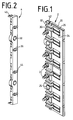
- Each connector assembly includes a base member, generally designated 2, as shown in FIG. 1 and a strain relief member, generally designated 4, as shown in FIG. 2.
- the base element 2 comprises a base part 20 and pins 22, which are used to align the base element 2 with the strain relief element 4. Openings 24 are provided which are used for connection to the wall plate or a similar piece of equipment.
- a plurality of grooves 26 are provided for receiving contacts 30.
- the preferred shape of the base portion 20 includes eight pairs of grooves 26 for receiving eight pairs of individual contacts 30 for connection to eight pairs of communication wires (not shown).
- the base part 20 is formed with wire connection ends 32 for input wires and contact areas 34. Each of the contacts 30 extends into the respectively associated contact area 34.
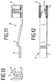
- the contacts 30 contain a wire connection means 70 (FIG. 13) at the wire connection end 32 in order to establish an electrical connection between a communication wire and an associated contact 30.
- the wire connection means 70 is preferably designed as a cutting / clamping contact.
- the strain relief element 4 is arranged above the communication wires. This creates a holder (strain relief) for the wires.
- the base element 2 connected to the strain relief element 4 forms an assembly 80 (FIG. 26).
- the assembly 80 is then brought together or connected to a similar (preferably identical) assembly 80.
- a plurality of assemblies 80 on each connection side can be connected or stacked to form stack assemblies 82 (see FIG. 26).
- a tap 16 can be arranged between the assembled assemblies 80, which will be explained in more detail below.
- the strain relief element 4 contains a multiplicity of connecting pins 36. These connecting pins 36 allow a multiplicity of assemblies 80 to be stacked.
- the strain relief element 4 furthermore contains openings 38 which are aligned with the openings 24 of the base element 2 when the strain relief element 4 is connected to the base element 2 is.
- the strain relief element 4 contains a latching means with a latching opening 40 for receiving a latching element 42 of the base element 2.
- the strain relief element 4 contains a multiplicity of wire connecting and clamping elements 41. These elements 41 press the wires down and serve to fasten the wires.
- the clamping elements 41 form part of the wire connecting and clamping means of the assembly 80.
- the connecting pins 36 are preferably substantially cylindrical. These male connecting pins 36 have a beveled or conical tip 44 through which the connecting pins 36 can slide into the corresponding slotted receiving openings 46 of the base element 2 (see FIG. 6).
- the base part 20 is preferably a single injection-molded plastic part.
- the base part 20 is formed with slotted openings 46, 48.
- the slotted openings 46 receive the connecting pins 36 of the strain relief element 4 from a further assembly 80, as a result of which a plurality of assemblies 80 can be stacked to form the stack assemblies 82.
- the slotted openings 48 on the other side receive connecting elements 50 from a further assembly 80.
- the connecting elements 50 are provided with a conical tip 52 and a connecting web part 54, which connects the connecting element 50 to the rest of the base part 20 (see, for example, FIG. 10).
- a slot 56 of the slotted opening 48 (the slotted opening 46 is the same) allows the connecting element 50 to be connected to its associated base part 20 via webs. The webs run through the slot 56 when the connecting element 36, 38, 50 slides into the opening 46, 48.
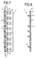
- Fig. 7 shows the base element 2 without the contacts 30 in a plan view.
- 8, 9 and 10 show different cross-sectional views of the base element 2 along the various cross-sectional lines 8-8, 9-9 and 10-10 in FIG. 7.
- Each of the cross-sectional views according to FIGS. 8, 9 and 10 shows the slotted openings 48. 8 and 9 show the slot 56.
- the contact 30 preferably has a connection end (wire connection means) 70 which is arranged adjacent to the wire connection end 32 of the base element 2.
- the contact 30 furthermore has a contact surface 71 which is arranged on the contact region 34 of the base element 2.
- each connection end 70 has opposite cutting / clamping elements 74.
- the cutting / clamping elements 74 are preferably supported by a U-shaped carrier 76.
- the U-shaped support 76 also provides the cutting / clamping elements 74 with a certain elasticity and provides the pressure necessary to maintain contact between the core and the cutting / clamping element 74.
- This structure allows a wire to be between the cutting / Clamping element 74 and the elasticity-providing U-shaped support 76 can be clamped.
- the cutting / clamping elements 74 cut the insulation of the wire and make contact with the wire core, so as to enable an electrical connection from the wire to the contact 30.
- the cutting / clamping element 74 can be formed from the same piece of metal as the U-shaped carrier 76 and can be punched out in order to arrange the cutting / clamping element 74 at an angle to a wire arranged within the U-shaped carrier 76.
- the contact 30 contains a contact arm 78, which has a contact surface 71 (see FIG. 14), and an actuating end 72, which will be explained in more detail later.
- the contact arm 78 is preferably designed to be elastic, as a result of which the contact surface 71 can be moved relative to the base element 2, namely can be pressed towards the base part 20 (into a non-contact position). This movement preferably results in a movement of the contact surface 71 into or towards the groove 26.
- the contact surface 71 extends from the groove 26 (into a contact position).
- the invention provides a mechanism for moving the contact surface 71 of each contact 30 between the contact position and the non-contact position. This is achieved in that one or more contact opening devices 84, 92 are provided which press the contact 30 into the non-contact position or allow the contact 30 to remain in the contact position.
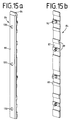
- 15a shows an actuating side 88 of an upper contact opening device 84.
- the contact opening device 84 has an inclined upper edge 86.
- 15b shows the upper contact opening device 84 with a plurality of connector pins 90.
- the connector pins 90 connect the upper contact opening device 84 to an upper part of the base element 2 with an actuating end 72 of the contact 30, which is arranged between the contact opening device 84 and the base element 2.
- the contact side 87 of the upper contact opening device 84 has a multiplicity of contact surfaces 89 which press the contact 30 into the non-contact position.
- the connector pins 90 can be provided such that they run through a contact 30 and are then attached to the base part 20.
- each contact 30 is seated in a corresponding groove 26.
- the connector pins 90 are then arranged next to the contacts 30 and preferably extend beyond the contacts 30 in a region between contact groups (see FIG. 17).
- each connector pin 90 runs into an opening 120 provided in the base part 20.
- the connector pin 90 can be provided with a latching element which prevents the contact opening device 84 from being detached from the base part 20. The distance between the latching element and the contact surface 89 of the contact opening device 84 is set such that the contact opening device 84 can move relative to the base part 20, as will be described below.
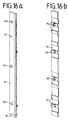
- the preferred embodiment of the electrical connector further includes a lower contact opening device 92 which is an oblique Has lower edge 94.
- 16a shows the actuation side 96.
- FIG. 16b shows the contact side 95.
- a multiplicity of connector pins 98 are provided for connecting the lower contact opening device 92 to a lower part of the base element 2.
- the contact side 95 has a plurality of contact surface parts 97. These correspond to the number of contacts 30.
- the contact surface parts 97 are provided for moving a lower set of contacts 30 from the contact position into the non-contact position by pressing the actuating end 72 of the contact 30.
- the connector pins 98 are each connected to a corresponding connector pin opening 120 in the base part 20, as described above with reference to the connector pins 90. Again, the end of the connector pins 98 holds the contact opening device 92 in connection with the base member 20, but allows some movement towards and away from the base member 20, as will be described below.
- Each of the upper contact opening devices 84 and lower contact opening devices 92 has a plurality of knobs 130. These knobs 130 are in the form of protruding parts. The knobs 130 extend from the surface of the actuation side 88 of the upper contact opening device 84, and in the same way the knobs 130 extend from the surface of the actuation side 96 of the contact opening device 92.
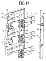
- FIG. 17 is an exploded view showing the contacts 30, the upper contact opening device 84 and a base part 20.
- the grooves 26 for the positioning of the contacts 30 are provided for receiving the contacts 30.
- the connector pin 90 of the upper contact opening device 84 is snapped into the openings 120 and is held by the end of the connector pin 90.
- the length of the connector pin 90 is designed with respect to the width of the base part 20 so that the contact opening device 84 can move away from and towards the base part 20. This degree of movement allows the contact opening device 84 to push the actuating end 72 of the contact 30 so that the contact 30 is moved to a non-contact position (the contact surface 71 is moved towards the socket part 20 so that it is not in physical contact with an opposite contact surface 71 of an opposite connector located).
- the elastic configuration of the contacts 30, in particular the contact arm 78 normally pushes the contact opening device 84 away from the base part 20.
- FIG. 18 shows the position of the contact opening device 84 and the contacts 30 in the case of two different connector assemblies.
- the contacts 30 are shown in the contact position (the contact surface 71 of each contact 30 is in physical contact with a contact surface 71 of an opposite contact 30).
- movement of one or both contact opening devices 84 in the direction of their associated base part 20 of the associated assemblies 80 results in the contact 30 being moved out of the contact position.
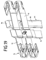
- FIG. 19 provides a perspective view of the relationship between the mated contacts 30 and the respective contact opening devices 84.
- FIG. 19 also shows the inclined top edge 86 which facilitates the passage of a tap 16 into the space between the contacts 30.
- the 20 shows an assembly 80 with the base element 2 including the base part 20, the contacts 30, the upper contact opening device 84 and the lower contact opening device 92.
- the upper contact opening device 84 and the lower contact opening device 92 are on the plug part via the connector pins 90 and 98, respectively 20 attached.
- the strain relief element 4 is connected to the base part 20 with the wires 12 (within wire bundles) with the contacts 30.
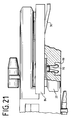
- the connection of the contact opening device 84 to the base part 20 is best seen in Fig. 21.
- the base part 20 is formed with receptacle bases 99, each receptacle base 99 being used to receive widening parts of the connector pin 90.
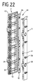
- a preferred embodiment of the assembly 80 is shown in an exploded view in FIG. 22.
- the lower part of the strain relief element 4 is cut away. Nevertheless, it can be seen from this exploded view that the strain relief element 4 snaps into the latching opening 40 with the latching element 42 according to the preferred embodiment.
- the base element 2 With a wire connected to each of the contacts 30, the base element 2 is connected to the strain relief element 4 by pressing the notches 41 into the associated latching openings. This is provided by assembly 80.
- the base part 20 can be connected to eight wire pairs 12.
- the contacts 30 are arranged in pairs of two in pairs 26 of grooves.
- the terminal end 70 of each contact 30 is connected to a wire.
- the lower half of the base element 2 also contains eight contacts, namely four pairs of contacts.
- eight pairs of wires can be connected to the base part 20, which then forms an assembly 80 with the strain relief element 4.
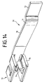
- a tap 16 is provided for connecting the communication wire 12 to the end user at the workstation via the base element 2.
- the tap 16 has a user interface part 60.
- the user interface part 60 contains a multiplicity of cutting / clamping contacts 62.
- Wires to the user at the workstation can be connected to a terminal strip or to the user interface part 60, each wire connected to a cutting / clamping contact 62 being connected to a corresponding communication wire 12 connected to the base element 2.
- the tap 16 has a multiplicity of contacts 66 on a contact tap side 67 of the tap 16.
- the connection between the contacts 62 and the contacts 66 can take place by means of a printed circuit board (tracks, etc.) attached to or in the contact tap side 67.
- the tap has an insulation side 68 that is free of contacts.
- the tap 16 taps a signal from a series of contacts 30 from an assembly 80 from two assembled assemblies 80.
- the tap 16 interrupts the signal to the other module 80 due to the insulation side 68.
- the tap 16 has an oblique edge 69, which facilitates the insertion of the tap 16 into the space between two connector modules 80 brought together.
- the preferred shape of the tap 16 provides eight contacts 66 which are connected to eight of the sixteen contacts 30 of an assembly 80, either with an upper set of contacts 30 or a lower set, depending on whether the tap 16 is inserted from above or from below (the tap 16 is connected to the upper contact opening device 84 from above and to the lower contact opening device 92 from below).
- the upper opening 100 formed by two assembled assemblies 80 provides access to the upper contact opening device 84 of a first assembly 80 and to the upper contact opening device 84 of a second assembly 80.
- a similar (substantially identical) arrangement is provided with respect to the bottom of the assembled assemblies 80.
- the oblique edge 69 of the tap 16 is inserted into the insertion opening 100.
- each contact opening device 84, 92 has knobs 130.
- the tap 16 is provided with a plurality of receiving spaces for the knobs 130, preferably in the form of holes 132 (see FIG. 23).
- the beveled edge 69 presses each contact opening device 84, 92 to their respective base part 20.
- the tapping surfaces 67 and 68 then come into contact with the knobs 130, which ensure that the various contacts 30 move out of the contact position (into the non-contact position), in which the contact surfaces 71 are separated.
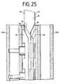
- the tap 16 is fully inserted into the unit, there is an alignment between the knobs 130 and the corresponding holes or openings 132.
- the tapered edge 69 of the tap 16 comes into contact with the top tapered surface 86 of each of the two contact opening devices 84.
- the contacts 30 move from the contact position the non-contact position.
- the connection between, for example, a left module L80 and a right module R80 is disconnected.
- the tap 16 is fully inserted, only the contacts 30, which are located on the contact side 67 of the tap 16, establish an electrical connection with the contacts 66 of the tap 16.
- the contact side 67 in the tap 16 shown is on the right side, so that the contacts 30 of the module R80 are in electrical contact with the various contacts 66 of the tap 16 when the tap is fully inserted. This taps the signal and contacts 30 of module L80 are separated from the signal.
- Fig. 26 shows a plurality of stacked assemblies 80.
- the connecting element 36 of each strain relief element 4 (except the first strain relief element 4) is connected to the slotted openings 46 of the assemblies 80 directly in front of it. This provides an assembly stack 82.
- an assembly stack 82 is brought together with an essentially identical assembly stack 82.
- the assemblies 80 consist of identical parts.
- Each strain relief element 4 and each base element 2 or base part 20 is preferably made with the same geometry. This allows only two molds to be used for these parts.
- the assemblies 80 are still hermaphrodite assemblies.
- a third mold is used to manufacture the third and fourth parts, namely the upper contact opening device 84 and the lower contact opening device 92.
- the so-called hermaphrodite nature of the connectors is evident when one considers that the connecting elements 50 have a male part and the slotted openings 48 form a female part.
- Each assembly 80 has both male and female parts which form part of the connector.
- the tap 16 can be provided at any point where a connection is to be provided to a user at a workstation.
- a connection is to be provided to a user at a workstation.
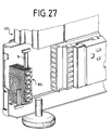
- many wall panels 200 are erected in which the data / voice lines from the wires of one wall panel 200 to the wires of another wall panel 200 need only be carried out.
- a tap 16 is required in order to make the data or voice connection available to a user at a workstation.
- the contacts 66 make electrical contact with corresponding contacts 30 of an assembly 80, thereby giving a user access to the data and Receives voice lines.
- the lines are dead behind the tapped contacts 30 of the assembled modules 80, since the insulation side 68 of the tap 16 does not make any contact with the contacts 30 of the opposite or brought-together module 80.
- FIG. 28 shows a base element 2 with contacts 30 and contact opening devices 84.
- this element is provided with a strain relief element 4.
- the strain relief element 4 is connected to one end of the base element 2 as shown.
- a single base element 2 with connected strain relief element 4 can be brought together with a further base element 2 with strain relief element 4.
- the latching opening 40 of the strain relief element 4 is connected to the latching element 42 of a further base element 2, as a result of which one base element 2 can be brought together with another.
- This is useful when a stack 82 of assemblies 80 is not needed and eight lines or less need to be interconnected.
- This arrangement still provides the same opening 100 so that in this alternative embodiment of the invention the tap 16 is inserted in the same way as in the assembled stacks 82 of assemblies 80.
Landscapes
- Connector Housings Or Holding Contact Members (AREA)
- Details Of Connecting Devices For Male And Female Coupling (AREA)
- Coupling Device And Connection With Printed Circuit (AREA)
- Multi-Conductor Connections (AREA)
- Connections By Means Of Piercing Elements, Nuts, Or Screws (AREA)
- Structure Of Telephone Exchanges (AREA)
- Telephone Set Structure (AREA)
- Casings For Electric Apparatus (AREA)
Applications Claiming Priority (2)
| Application Number | Priority Date | Filing Date | Title |
|---|---|---|---|
| US08/651,414 US5816836A (en) | 1996-05-22 | 1996-05-22 | High density high performance connector |
| US651414 | 2000-08-30 |
Publications (1)
| Publication Number | Publication Date |
|---|---|
| EP0809332A1 true EP0809332A1 (fr) | 1997-11-26 |
Family
ID=24612771
Family Applications (1)
| Application Number | Title | Priority Date | Filing Date |
|---|---|---|---|
| EP97108131A Withdrawn EP0809332A1 (fr) | 1996-05-22 | 1997-05-20 | Connecteur électrique |
Country Status (25)
| Country | Link |
|---|---|
| US (1) | US5816836A (fr) |
| EP (1) | EP0809332A1 (fr) |
| JP (1) | JPH1050391A (fr) |
| KR (1) | KR970077839A (fr) |
| CN (1) | CN1182296A (fr) |
| AR (1) | AR007199A1 (fr) |
| BG (1) | BG62585B1 (fr) |
| BR (1) | BR9703372A (fr) |
| CA (1) | CA2205754A1 (fr) |
| CZ (1) | CZ288281B6 (fr) |
| HR (1) | HRP970280A2 (fr) |
| HU (1) | HUP9700901A3 (fr) |
| ID (1) | ID16697A (fr) |
| IL (1) | IL120829A (fr) |
| NO (1) | NO972137L (fr) |
| NZ (1) | NZ314789A (fr) |
| PL (1) | PL320055A1 (fr) |
| RO (1) | RO119800B1 (fr) |
| SG (1) | SG55318A1 (fr) |
| SK (1) | SK62697A3 (fr) |
| TR (1) | TR199700412A3 (fr) |
| TW (1) | TW363290B (fr) |
| UA (1) | UA41423C2 (fr) |
| YU (1) | YU21097A (fr) |
| ZA (1) | ZA974408B (fr) |
Cited By (1)
| Publication number | Priority date | Publication date | Assignee | Title |
|---|---|---|---|---|
| EP0954076A2 (fr) * | 1998-04-27 | 1999-11-03 | KRONE Aktiengesellschaft | Liaison haute performance de données et de télécommunication avec connecteur à haute densité avec prise et bloc de contact de déplacement |
Families Citing this family (7)
| Publication number | Priority date | Publication date | Assignee | Title |
|---|---|---|---|---|
| US5964609A (en) * | 1995-01-25 | 1999-10-12 | Haworth, Inc. | Modular communication cabling arrangement |
| US6089892A (en) | 1998-04-27 | 2000-07-18 | Haworth, Inc. | Telecommunications cabling arrangement |
| ES2234793T3 (es) * | 2001-03-29 | 2005-07-01 | 3M Innovative Properties Company | Regleta de terminales para interconectar lineas. |
| US20040132330A1 (en) * | 2001-03-29 | 2004-07-08 | Pierre Bonvallat | Terminal strip for interconnecting lines |
| CN104363527B (zh) * | 2014-09-24 | 2017-09-08 | 国家电网公司 | 可快速切换的配线架 |
| DE102015114701B4 (de) | 2015-09-03 | 2019-01-31 | Harting Electric Gmbh & Co. Kg | Halterahmen mit Sperrelement |
| US11570923B1 (en) * | 2021-08-30 | 2023-01-31 | Quanta Computer Inc. | Base and clip assembly |
Citations (3)
| Publication number | Priority date | Publication date | Assignee | Title |
|---|---|---|---|---|
| FR2583929A1 (fr) * | 1985-06-25 | 1986-12-26 | Boga Sa | Reglette modulaire pour repartiteur telephonique |
| FR2595011A1 (fr) * | 1986-02-26 | 1987-08-28 | Pouyet Henri | Reglette de raccordement multifonctions |
| US5205762A (en) * | 1991-12-06 | 1993-04-27 | Porta Systems Corp. | High frequency patch cord data connector |
Family Cites Families (29)
| Publication number | Priority date | Publication date | Assignee | Title |
|---|---|---|---|---|
| US3638164A (en) * | 1970-04-23 | 1972-01-25 | Ford Motor Co | Bisexual electrical connector |
| CA1072649A (fr) * | 1976-01-07 | 1980-02-26 | Robert H. Frantz | Fiche isolante ou demi-elements |
| US4382648A (en) * | 1977-08-18 | 1983-05-10 | Herman Miller, Inc. | Electrical energy supply system for work stations in a space divider system |
| US4349239A (en) * | 1980-07-03 | 1982-09-14 | Amp Incorporated | Low mating force connector for connecting groups of wires |
| US4781609A (en) * | 1984-08-10 | 1988-11-01 | Haworth, Inc. | Wall system with multicircuit electrical system |
| US4898549A (en) * | 1986-01-28 | 1990-02-06 | Omron Tateisi Electronics Co. | Connector built from one or more single rowed housings, with long lasting locking mechanism |
| US4795356A (en) * | 1987-01-20 | 1989-01-03 | Amp Incorporated | Electrical tap connector assembly |
| FR2625380B1 (fr) * | 1987-12-29 | 1990-06-08 | Maitrise Reseaux | Dispositif de cablage des reseaux basse tension et tres basse tension d'un batiment |
| US5158472A (en) * | 1989-02-21 | 1992-10-27 | Steelcase Inc. | Modular powerway for office furniture and the like |
| US4973796A (en) * | 1989-08-10 | 1990-11-27 | Visu-Wall By Hbsa Industries, Inc. | Electrified wall structure |
| US5203713A (en) * | 1989-08-16 | 1993-04-20 | Amp Incorporated | Power distribution system for modular furniture unit |
| US5214889A (en) * | 1990-01-18 | 1993-06-01 | Herman Miller, Inc. | Electrified wall panel system |
| US5171159A (en) * | 1990-08-22 | 1992-12-15 | Byrne Norman R | Electrical interconnection assembly |
| US5272277A (en) * | 1990-10-26 | 1993-12-21 | Holscher-Wernig, Inc. | Telecommunications wiring system |
| US5104332A (en) * | 1991-01-22 | 1992-04-14 | Group Dekko International | Modular furniture power distribution system and electrical connector therefor |
| US5164544A (en) * | 1991-03-13 | 1992-11-17 | Westinghouse Electric Corp. | Electrified space dividing panel |
| FR2675953B1 (fr) * | 1991-04-26 | 1993-07-02 | Entrelec Sa | Agencement de connexion pour fils electriques et piece de connexion pour un tel agencement. |
| US5160276A (en) * | 1991-07-09 | 1992-11-03 | Group Dekko International | Modular communication interconnection system |
| US5203711A (en) * | 1991-10-01 | 1993-04-20 | Molex Incorporated | Modular interchangeable power distribution system |
| US5186640A (en) * | 1992-02-24 | 1993-02-16 | Group Dekko International | Wiring harness assembly |
| US5277609A (en) * | 1992-05-28 | 1994-01-11 | Steelcase Inc. | Modular powderway for partition panels and the like (C-39) |
| US5252086A (en) * | 1992-05-28 | 1993-10-12 | Steelcase Inc. | Modular powerway with selectable receptacle |
| US5236370A (en) * | 1992-06-05 | 1993-08-17 | Haworth, Inc. | Electrical system for interior space-dividing system |
| EP0573047A1 (fr) * | 1992-06-05 | 1993-12-08 | Rhc/Spacemaster Corporation | Système modulaire de distribution d'énergie |
| US5349135A (en) * | 1992-06-08 | 1994-09-20 | Rosemount Office Systems, Inc. | Fastener for electrical power distribution in divider panels |
| JP2698841B2 (ja) * | 1992-10-28 | 1998-01-19 | 矢崎総業株式会社 | 低挿入力コネクタ |
| US5318454A (en) * | 1992-12-15 | 1994-06-07 | Steelcase Inc. | Off-module bus electrical system (C-13) |
| US5431584A (en) * | 1994-01-21 | 1995-07-11 | The Whitaker Corporation | Electrical connector with reduced crosstalk |
| US5431578A (en) * | 1994-03-02 | 1995-07-11 | Abrams Electronics, Inc. | Compression mating electrical connector |
-
1996
- 1996-05-22 US US08/651,414 patent/US5816836A/en not_active Expired - Fee Related
-
1997
- 1997-05-09 NO NO972137A patent/NO972137L/no not_active Application Discontinuation
- 1997-05-12 BG BG101480A patent/BG62585B1/bg unknown
- 1997-05-12 NZ NZ314789A patent/NZ314789A/en unknown
- 1997-05-14 IL IL12082997A patent/IL120829A/en not_active IP Right Cessation
- 1997-05-14 SG SG1997001661A patent/SG55318A1/en unknown
- 1997-05-14 HU HU9700901A patent/HUP9700901A3/hu unknown
- 1997-05-14 CZ CZ19971474A patent/CZ288281B6/cs not_active IP Right Cessation
- 1997-05-16 UA UA97052266A patent/UA41423C2/uk unknown
- 1997-05-19 PL PL97320055A patent/PL320055A1/xx unknown
- 1997-05-20 AR ARP970102120A patent/AR007199A1/es unknown
- 1997-05-20 RO RO97-00924A patent/RO119800B1/ro unknown
- 1997-05-20 SK SK626-97A patent/SK62697A3/sk unknown
- 1997-05-20 EP EP97108131A patent/EP0809332A1/fr not_active Withdrawn
- 1997-05-21 HR HR08/651,414A patent/HRP970280A2/hr not_active Application Discontinuation
- 1997-05-21 ZA ZA974408A patent/ZA974408B/xx unknown
- 1997-05-21 ID IDP971676A patent/ID16697A/id unknown
- 1997-05-21 CA CA002205754A patent/CA2205754A1/fr not_active Abandoned
- 1997-05-22 TR TR97/00412A patent/TR199700412A3/tr unknown
- 1997-05-22 CN CN97113286A patent/CN1182296A/zh active Pending
- 1997-05-22 KR KR1019970020015A patent/KR970077839A/ko not_active Application Discontinuation
- 1997-05-22 YU YU21097A patent/YU21097A/sh unknown
- 1997-05-22 BR BR9703372A patent/BR9703372A/pt active Search and Examination
- 1997-05-22 JP JP9132274A patent/JPH1050391A/ja active Pending
- 1997-05-31 TW TW086106894A patent/TW363290B/zh active
Patent Citations (3)
| Publication number | Priority date | Publication date | Assignee | Title |
|---|---|---|---|---|
| FR2583929A1 (fr) * | 1985-06-25 | 1986-12-26 | Boga Sa | Reglette modulaire pour repartiteur telephonique |
| FR2595011A1 (fr) * | 1986-02-26 | 1987-08-28 | Pouyet Henri | Reglette de raccordement multifonctions |
| US5205762A (en) * | 1991-12-06 | 1993-04-27 | Porta Systems Corp. | High frequency patch cord data connector |
Cited By (2)
| Publication number | Priority date | Publication date | Assignee | Title |
|---|---|---|---|---|
| EP0954076A2 (fr) * | 1998-04-27 | 1999-11-03 | KRONE Aktiengesellschaft | Liaison haute performance de données et de télécommunication avec connecteur à haute densité avec prise et bloc de contact de déplacement |
| EP0954076A3 (fr) * | 1998-04-27 | 2003-11-19 | KRONE GmbH | Liaison haute performance de données et de télécommunication avec connecteur à haute densité avec prise et bloc de contact de déplacement |
Also Published As
| Publication number | Publication date |
|---|---|
| JPH1050391A (ja) | 1998-02-20 |
| AU713140B2 (en) | 1999-11-25 |
| NZ314789A (en) | 1998-11-25 |
| CN1182296A (zh) | 1998-05-20 |
| NO972137D0 (no) | 1997-05-09 |
| SG55318A1 (en) | 1998-12-21 |
| MX9703739A (es) | 1998-06-28 |
| IL120829A (en) | 2001-10-31 |
| BR9703372A (pt) | 1998-09-08 |
| UA41423C2 (uk) | 2001-09-17 |
| AR007199A1 (es) | 1999-10-13 |
| TR199700412A2 (xx) | 1997-12-21 |
| TR199700412A3 (tr) | 1997-12-21 |
| PL320055A1 (en) | 1997-11-24 |
| BG101480A (en) | 1997-12-30 |
| CZ288281B6 (en) | 2001-05-16 |
| AU2139797A (en) | 1997-11-27 |
| CZ147497A3 (en) | 1997-12-17 |
| NO972137L (no) | 1997-11-24 |
| HUP9700901A2 (hu) | 1998-01-28 |
| HRP970280A2 (en) | 1998-02-28 |
| IL120829A0 (en) | 1997-09-30 |
| SK62697A3 (en) | 1998-06-03 |
| US5816836A (en) | 1998-10-06 |
| YU21097A (sh) | 2002-09-19 |
| RO119800B1 (ro) | 2005-03-30 |
| CA2205754A1 (fr) | 1997-11-22 |
| KR970077839A (ko) | 1997-12-12 |
| BG62585B1 (bg) | 2000-02-29 |
| ZA974408B (en) | 1998-11-23 |
| TW363290B (en) | 1999-07-01 |
| HU9700901D0 (en) | 1997-06-30 |
| HUP9700901A3 (en) | 1998-12-28 |
| ID16697A (id) | 1997-11-06 |
Similar Documents
| Publication | Publication Date | Title |
|---|---|---|
| EP1693934B1 (fr) | Connecteur pour la transmission de données par des fils électriques | |
| DE10203162B4 (de) | Verbinder | |
| EP0595234B1 (fr) | Connecteur de câble pour câbles multibrins | |
| DE3843664C2 (fr) | ||
| DE69836510T2 (de) | Nachrichtenstecker | |
| DE2338056B2 (de) | Elektrische Anschlußklemme | |
| EP0789427A2 (fr) | Connecteur pour plaque de circuit imprimé | |
| EP1022809A2 (fr) | Appareil électrique | |
| DE4121313A1 (de) | Verdrahtungsverteilungssystem und einrichtungen zum aufbauen einer verdrahtung | |
| EP1128494A2 (fr) | Adaptateur et connecteur pour technique de commande et de communication | |
| DE19902745A1 (de) | Elektrisches Gerät | |
| EP0954076A2 (fr) | Liaison haute performance de données et de télécommunication avec connecteur à haute densité avec prise et bloc de contact de déplacement | |
| EP0809332A1 (fr) | Connecteur électrique | |
| DE3019412C2 (fr) | ||
| EP0856911A1 (fr) | Bloc de connexion multipolaire | |
| DE10230292B3 (de) | Träger für Modulgehäuse | |
| EP0650217A1 (fr) | Dispositif de connexion de fils notamment pour des installation à courant faible | |
| EP0921611B1 (fr) | Prise et interrupteur pour le secteur | |
| EP1897382B1 (fr) | Dispositif de repartition d'une installation de telecommunication | |
| DE2712723A1 (de) | Elektrischer verteiler | |
| EP1518298A1 (fr) | Dispositif de derivation pour ligne electrique | |
| EP1129461B1 (fr) | Relais a element de couplage | |
| EP0127849A2 (fr) | Relais | |
| DE10033841B4 (de) | Abzweigvorrichtung | |
| DE3346381A1 (de) | Installationsverteilersystem |
Legal Events
| Date | Code | Title | Description |
|---|---|---|---|
| PUAI | Public reference made under article 153(3) epc to a published international application that has entered the european phase |
Free format text: ORIGINAL CODE: 0009012 |
|
| AK | Designated contracting states |
Kind code of ref document: A1 Designated state(s): AT BE CH DE DK ES FI FR GB GR IE IT LI LU MC NL PT SE |
|
| AX | Request for extension of the european patent |
Free format text: LT PAYMENT 970520;LV PAYMENT 970520;SI PAYMENT 970520 |
|
| 17P | Request for examination filed |
Effective date: 19971010 |
|
| RAP1 | Party data changed (applicant data changed or rights of an application transferred) |
Owner name: KRONE GMBH |
|
| 17Q | First examination report despatched |
Effective date: 20000825 |
|
| STAA | Information on the status of an ep patent application or granted ep patent |
Free format text: STATUS: THE APPLICATION IS DEEMED TO BE WITHDRAWN |
|
| 18D | Application deemed to be withdrawn |
Effective date: 20021203 |