EP0809268B1 - Hochspannungs-Leistungsschalter mit einer Isolierstoffdüse - Google Patents
Hochspannungs-Leistungsschalter mit einer Isolierstoffdüse Download PDFInfo
- Publication number
- EP0809268B1 EP0809268B1 EP97250162A EP97250162A EP0809268B1 EP 0809268 B1 EP0809268 B1 EP 0809268B1 EP 97250162 A EP97250162 A EP 97250162A EP 97250162 A EP97250162 A EP 97250162A EP 0809268 B1 EP0809268 B1 EP 0809268B1
- Authority
- EP
- European Patent Office
- Prior art keywords
- nozzle
- clamping ring
- circuit breaker
- voltage circuit
- dielectric material
- Prior art date
- Legal status (The legal status is an assumption and is not a legal conclusion. Google has not performed a legal analysis and makes no representation as to the accuracy of the status listed.)
- Expired - Lifetime
Links
- 239000011810 insulating material Substances 0.000 title description 9
- 239000011324 bead Substances 0.000 claims description 10
- 230000005489 elastic deformation Effects 0.000 claims description 3
- 238000010791 quenching Methods 0.000 claims description 3
- 230000000171 quenching effect Effects 0.000 claims description 3
- 239000003989 dielectric material Substances 0.000 claims 7
- 230000002093 peripheral effect Effects 0.000 claims 1
- 230000008878 coupling Effects 0.000 description 6
- 238000010168 coupling process Methods 0.000 description 6
- 238000005859 coupling reaction Methods 0.000 description 6
- 239000007789 gas Substances 0.000 description 4
- 238000000926 separation method Methods 0.000 description 4
- 230000001133 acceleration Effects 0.000 description 2
- 230000005540 biological transmission Effects 0.000 description 2
- 241000722921 Tulipa gesneriana Species 0.000 description 1
- 238000007664 blowing Methods 0.000 description 1
- 230000006835 compression Effects 0.000 description 1
- 238000007906 compression Methods 0.000 description 1
- 238000010276 construction Methods 0.000 description 1
- 238000005553 drilling Methods 0.000 description 1
- 230000005684 electric field Effects 0.000 description 1
- 230000002349 favourable effect Effects 0.000 description 1
- 238000010438 heat treatment Methods 0.000 description 1
- 238000002955 isolation Methods 0.000 description 1
Images

Classifications
-
- H—ELECTRICITY
- H01—ELECTRIC ELEMENTS
- H01H—ELECTRIC SWITCHES; RELAYS; SELECTORS; EMERGENCY PROTECTIVE DEVICES
- H01H33/00—High-tension or heavy-current switches with arc-extinguishing or arc-preventing means
- H01H33/70—Switches with separate means for directing, obtaining, or increasing flow of arc-extinguishing fluid
- H01H33/7015—Switches with separate means for directing, obtaining, or increasing flow of arc-extinguishing fluid characterised by flow directing elements associated with contacts
- H01H33/7023—Switches with separate means for directing, obtaining, or increasing flow of arc-extinguishing fluid characterised by flow directing elements associated with contacts characterised by an insulating tubular gas flow enhancing nozzle
-
- H—ELECTRICITY
- H01—ELECTRIC ELEMENTS
- H01H—ELECTRIC SWITCHES; RELAYS; SELECTORS; EMERGENCY PROTECTIVE DEVICES
- H01H33/00—High-tension or heavy-current switches with arc-extinguishing or arc-preventing means
- H01H33/02—Details
- H01H2033/028—Details the cooperating contacts being both actuated simultaneously in opposite directions
-
- H—ELECTRICITY
- H01—ELECTRIC ELEMENTS
- H01H—ELECTRIC SWITCHES; RELAYS; SELECTORS; EMERGENCY PROTECTIVE DEVICES
- H01H33/00—High-tension or heavy-current switches with arc-extinguishing or arc-preventing means
- H01H33/02—Details
- H01H33/24—Means for preventing discharge to non-current-carrying parts, e.g. using corona ring
- H01H33/245—Means for preventing discharge to non-current-carrying parts, e.g. using corona ring using movable field electrodes
-
- H—ELECTRICITY
- H01—ELECTRIC ELEMENTS
- H01H—ELECTRIC SWITCHES; RELAYS; SELECTORS; EMERGENCY PROTECTIVE DEVICES
- H01H33/00—High-tension or heavy-current switches with arc-extinguishing or arc-preventing means
- H01H33/70—Switches with separate means for directing, obtaining, or increasing flow of arc-extinguishing fluid
- H01H33/88—Switches with separate means for directing, obtaining, or increasing flow of arc-extinguishing fluid the flow of arc-extinguishing fluid being produced or increased by movement of pistons or other pressure-producing parts
- H01H33/90—Switches with separate means for directing, obtaining, or increasing flow of arc-extinguishing fluid the flow of arc-extinguishing fluid being produced or increased by movement of pistons or other pressure-producing parts this movement being effected by or in conjunction with the contact-operating mechanism
- H01H33/901—Switches with separate means for directing, obtaining, or increasing flow of arc-extinguishing fluid the flow of arc-extinguishing fluid being produced or increased by movement of pistons or other pressure-producing parts this movement being effected by or in conjunction with the contact-operating mechanism making use of the energy of the arc or an auxiliary arc
Definitions
- the invention relates to a high-voltage circuit breaker with a first and a second, coaxial with each other opposing arcing contact piece, at least of which the first by a switch drive in the course of a Switching movement is drivable and in the off state are separated by a separation section and with a hollow cylindrical Insulating material nozzle with the first arcing contact is connected and the blowing of one if necessary burning between the arcing contact pieces Arc is used with an extinguishing gas, and to which one on the the side of the isolating section opposite the switch drive arranged component to be driven in the switching case coupled is.
- FR 2 491 675 is a high-voltage circuit breaker known with two coaxial arcing contact pieces and with an insulating nozzle, which with a drivable arcing contact piece is connected.
- the other arcing contact piece is by means of a reversing gear driven by a drive element, which in turn is connected to the switch drive and the isolating section bridged between the arcing contact pieces.
- the Coupling of the second drivable arcing contact piece can also be connected to the switch drive by means of the insulating material nozzle respectively. For this purpose it is necessary to use the insulating nozzle to attach a transmission element itself.
- the insulating nozzle is made of a plastic with limited strength and the corrosive influences the arc or hot extinguishing gases. Moreover the forces to be transmitted are very high when switching large, so that the coupling is mechanically stable have to be.
- the present invention is therefore based on the object a high-voltage circuit breaker of the type mentioned Kind of creating a stable coupling of a driven one Component allowed to the insulating nozzle.
- the insulating nozzle on its first, facing away from the drive side End has a bead arranged on a lateral surface, behind the one from the first end of the insulating nozzle Slid on first clamping ring with temporary radial elastic deformation of the first clamping ring and / or the Snap end of the nozzle and that a second clamping ring is provided, the first clamping ring and / or that Nozzle end to prevent unlocking the first Clamping ring supports and that the component to be driven at least one of the clamping rings can be coupled.
- the coupling of a component to be driven to the insulating nozzle allows without drilling holes in the nozzle must be the stability of the nozzle body if necessary could affect. Since all components from have to be pushed on the first end of the insulating material nozzle, because the other end of the insulating nozzle has a larger one Has diameter, elastic deformability must be provided be the sliding of the first tension ring allowed behind the bulge of the insulating material nozzle. After this The second clamping ring is put on and if necessary with the first clamping ring Screws or connected by another type of fastening.
- the first clamping ring is on the outside Slide on nozzle.
- the first tension ring will either do this expanded and / or the first end of the nozzle is compressed radially. This is due to radial slots at the end of the nozzle allows.
- the second clamping ring is put on, the in this case the radial compression of the nozzle end or must prevent the expansion of the first clamping ring.
- the second clamping ring has a nozzle that either inserted into the inside of the nozzle end or in a circumferential groove on the face of the nozzle body is inserted. The second clamping ring prevents the first clamping ring pushed over the bead and thus unlocked can be.
- the second clamping ring is either also into one on the front of the insulating nozzle circumferential groove inserted or on the outside of the nozzle body placed.
- the second clamping ring allows in particular the coupling of a transmission element, in particular one Insulating rod that drives a drive movement across the Isolation path over to the second arcing contact piece can transmit.
- a reversing gear provided in the form of a lever be actuated by the insulating rod so that the second arcing contact piece in the event of a shutdown of the the first arcing contact piece is moved away.
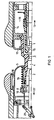
- FIG. 1 shows a first arcing contact piece 1 in one Half cut and a second arcing contact piece 2, wherein the first arcing contact 1 as a tulip contact and the second arcing contact piece 2 is designed as a contact pin is.
- the first arcing contact 1 is with a not shown Switch drive connected to the first arcing contact 1 when switching off in the direction of the arrow 13 moves.
- the first arcing contact 1 is with a metallic Connected hollow cylinder 14 which carries an insulating nozzle 3. Another insulating nozzle body 15 is directly on the first arcing contact piece 1 placed. Moved when switching the insulating material nozzle 3 with the first arcing contact piece 1 together.
- first and the second arcing contact pieces 1, 2 are separated from one another, an arc is drawn in the separating section 4 between them, which expands the quenching gas located there, for example SF 6 .
- the hot quenching gas can flow out into a heating chamber 16, from which it flows back at a suitable time, for example directly after a current zero crossing of the current to be switched, in order to blow the arc.
- the insulating material nozzle 3 bridges the separation path 4 both in the on state as well as in the off state.
- On the Drive opposite side of the separation section 4 is the Body of the insulating material surrounded by a field electrode 5, which is pressed towards the separation section by means of a spring 19 is going to be there in the on state for a dielectrically favorable Design of the electrical field between the contacts to care.
- the spring 19 is supported on the first clamping ring 8, which is attached to the first end 6 of the insulating nozzle 3 is.
- the spring 19 could also be on an outer bead support the insulating material nozzle itself.
- the field electrode 5 is through the continuous current contact piece 17 pushed back so far that this continuous current contact piece in contact with the other continuous current contact piece 18 can kick.
- the field electrode 5 is by means of a Slide contact performed in the continuous current contact piece 17 and contacted.
- a Drive rod 20 coupled, which is a deflection gear in the form a two-armed lever 21 operated on the other arm the second arcing contact piece 2 is coupled.
- first clamping ring 8 which the bead 7 pushed over from the first end 6 of the insulating nozzle 3 can be and snaps behind the bead 7. This is either by an elastic design of the nozzle, for example through radial slots at the nozzle end or through a slit of the first clamping ring 8 is reached.
- the both stabilizes the nozzle body 3 and the first clamping ring 8 in such a way that there is no elastic deformation and therefore no sliding over the first clamping ring 8 over the bead 7 more is possible.
- the second clamping ring 10 has a nozzle 11, which in the groove 12 engages on the end face of the nozzle body 3 and a radial deformation of the nozzle body both towards the inside and also prevented to the outside.
Landscapes
- Circuit Breakers (AREA)
Description
Claims (6)
- Hochspannungs-Leistungsschalter mit einem ersten und einem zweiten, einander koaxial gegenüberstehenden Lichtbogenkontaktstück (1, 2), von denen wenigstens das erste (1) durch einen Schalterantrieb im Zuge einer Schaltbewegung antreibbar ist und die im Ausschaltzustand durch eine Trennstrecke (4) getrennt sind sowie mit einer hohlzylindrischen Isolierstoffdüse (3), die mit dem ersten Lichtbogenkontaktstück (1) verbunden ist und der Beblasung eines gegebenenfalls zwischen den Lichtbogenkontaktstücken brennenden Lichtbogens mit einem Löschgas dient, und an die ein auf der dem Schalterantrieb gegenüberliegenden Seite der Trennstrecke (4) angeordnetes, im Schaltfall anzutreibendes Bauteil angekoppelt ist,
dadurch gekennzeichnet, daß
die Isolierstoffdüse (3) an ihrem der Antriebsseite abgewandten ersten Ende (6) eine an einer Mantelfläche angeordnete Wulst aufweist, hinter der ein von dem ersten Ende (6) der Isolierstoffdüse (3) her aufgeschobener erster Spannring (8) unter vorübergehender radialer elastischer Verformung des ersten Spannrings (8) und/oder des Düsenendes (6) einrastbar ist und daß ein zweiter Spannring (10) vorgesehen ist, der den ersten Spannring (8) und/oder das Düsenende (6) zur Verhinderung der Entriegelung des ersten Spannrings (8) stützt und daß das anzutreibende Bauteil an wenigstens einen der Spannringe (8, 10) ankoppelbar ist. - Hochspannungs-Leistungsschalter nach Anspruch 1,
dadurch gekennzeichnet, daß
das erste Ende (6) der Isolierstoffdüse (3) radiale, am Umfang der Düse verteilte Schlitze aufweist. - Hochspannungs-Leistungsschalter nach Anspruch 2,
dadurch gekennzeichnet, daß
der zweite Spannring (10) einen Stutzen (11) aufweist, der das erste Ende (6) der Isolierstoffdüse (3) umfaßt. - Hochspannungs-Leistungsschalter nach Anspruch 2,
dadurch gekennzeichnet, daß
der zweite Spannring (10) einen Stutzen (11) aufweist, der in das erste Ende (6) der Isolierstoffdüse (3) einschiebbar ist. - Hochspannungs-Leistungsschalter nach Anspruch 2,
dadurch gekennzeichnet, daß
der zweite Spannring (10) einen Stutzen (11) aufweist, der in eine umlaufende Nut (12) an der Stirnseite des ersten Endes (6) der Isolierstoffdüse (3) einschiebbar ist. - Hochspannungs-Leistungsschalter nach Anspruch 1 oder einem der folgenden,
dadurch gekennzeichnet, daß
der erste Spannring (8) durch einen radialen Schlitz aufweitbar ausgeführt ist.
Applications Claiming Priority (2)
| Application Number | Priority Date | Filing Date | Title |
|---|---|---|---|
| DE29609909U | 1996-05-24 | ||
| DE29609909U DE29609909U1 (de) | 1996-05-24 | 1996-05-24 | Hochspannungs-Leistungsschalter mit einer Isolierstoffdüse |
Publications (3)
| Publication Number | Publication Date |
|---|---|
| EP0809268A2 EP0809268A2 (de) | 1997-11-26 |
| EP0809268A3 EP0809268A3 (de) | 1998-12-02 |
| EP0809268B1 true EP0809268B1 (de) | 2004-08-18 |
Family
ID=8024802
Family Applications (1)
| Application Number | Title | Priority Date | Filing Date |
|---|---|---|---|
| EP97250162A Expired - Lifetime EP0809268B1 (de) | 1996-05-24 | 1997-05-23 | Hochspannungs-Leistungsschalter mit einer Isolierstoffdüse |
Country Status (2)
| Country | Link |
|---|---|
| EP (1) | EP0809268B1 (de) |
| DE (2) | DE29609909U1 (de) |
Cited By (1)
| Publication number | Priority date | Publication date | Assignee | Title |
|---|---|---|---|---|
| EP1686602A1 (de) * | 2005-02-01 | 2006-08-02 | ABB Technology AG | Düsenbefestigung für elektrisches Schaltgerät |
Families Citing this family (7)
| Publication number | Priority date | Publication date | Assignee | Title |
|---|---|---|---|---|
| DE29609909U1 (de) * | 1996-05-24 | 1996-08-22 | Siemens AG, 80333 München | Hochspannungs-Leistungsschalter mit einer Isolierstoffdüse |
| DE19631323C1 (de) * | 1996-08-01 | 1997-10-16 | Aeg Energietechnik Gmbh | Druckgasschalter |
| DE19948687C1 (de) * | 1999-09-30 | 2001-02-15 | Siemens Ag | Hochspannungsleistungsschalter |
| EP2325859B1 (de) | 2009-11-24 | 2013-04-17 | ABB Technology AG | Gasisolierter Hochspannungsschalter |
| DE102015205388A1 (de) * | 2015-03-25 | 2016-09-29 | Siemens Aktiengesellschaft | Isolierdüse und elektrische Schalteinrichtung mit der Isolierdüse |
| CN109192597B (zh) * | 2018-10-11 | 2020-02-04 | 西安西电开关电气有限公司 | 断路器及其双动传动装置 |
| DE102019214432B4 (de) * | 2019-09-23 | 2024-02-08 | Siemens Energy Global GmbH & Co. KG | Baugruppe für einen Hochspannungs-Leistungsschalter und entsprechender Hochspannungs-Leistungsschalter |
Family Cites Families (3)
| Publication number | Priority date | Publication date | Assignee | Title |
|---|---|---|---|---|
| FR2491675A1 (fr) * | 1980-10-07 | 1982-04-09 | Alsthom Atlantique | Dispositif de coupure a double mouvement des contacts |
| CH675175A5 (de) * | 1987-10-27 | 1990-08-31 | Bbc Brown Boveri & Cie | |
| DE29609909U1 (de) * | 1996-05-24 | 1996-08-22 | Siemens AG, 80333 München | Hochspannungs-Leistungsschalter mit einer Isolierstoffdüse |
-
1996
- 1996-05-24 DE DE29609909U patent/DE29609909U1/de not_active Expired - Lifetime
-
1997
- 1997-05-23 EP EP97250162A patent/EP0809268B1/de not_active Expired - Lifetime
- 1997-05-23 DE DE59711853T patent/DE59711853D1/de not_active Expired - Lifetime
Cited By (4)
| Publication number | Priority date | Publication date | Assignee | Title |
|---|---|---|---|---|
| EP1686602A1 (de) * | 2005-02-01 | 2006-08-02 | ABB Technology AG | Düsenbefestigung für elektrisches Schaltgerät |
| WO2006081697A1 (de) * | 2005-02-01 | 2006-08-10 | Abb Technology Ag | Düsenbefestigung für elektrisches schaltgerät |
| US7619177B2 (en) | 2005-02-01 | 2009-11-17 | Abb Technology Ag | Nozzle fastening for electrical switching apparatus |
| CN101111915B (zh) * | 2005-02-01 | 2012-04-18 | Abb技术有限公司 | 用于电动开关装置的断续器单元 |
Also Published As
| Publication number | Publication date |
|---|---|
| DE29609909U1 (de) | 1996-08-22 |
| EP0809268A2 (de) | 1997-11-26 |
| EP0809268A3 (de) | 1998-12-02 |
| DE59711853D1 (de) | 2004-09-23 |
Similar Documents
| Publication | Publication Date | Title |
|---|---|---|
| EP0809269B1 (de) | Hochspannungs-Leistungsschalter mit zwei antreibbaren Schaltkontaktstücken | |
| EP0435865B1 (de) | Lasttrennschalter, enthaltend eine vakuumschaltroehre und verfahren zum betrieb eines solchen lasttrennschalters | |
| EP1306868B1 (de) | Hochspannungsleistungsschalter mit einer Isolierstoffdüse | |
| EP0809268B1 (de) | Hochspannungs-Leistungsschalter mit einer Isolierstoffdüse | |
| DE60223766T2 (de) | Kontaktanordnung für einen Vakuumschalter und Vakuumschalter mit einer solchen Kontaktanordnung | |
| DE19803974C1 (de) | Kontaktanordnung für einen elektrischen Leistungsschalter | |
| EP0500550B1 (de) | Trennschalter für metallgekapselte, druckgasisolierte hochspannungsschaltanlagen | |
| DE3319010A1 (de) | Gasisolierter schalter | |
| EP0593498B1 (de) | Trennschalter mit einem hauptschaltstift und einem hilfskontaktstift | |
| CH660814A5 (de) | Elektrischer leistungsschalter. | |
| DE3341903C3 (de) | Hochspannungsleistungsschalter | |
| EP1443537B1 (de) | Anordnung mit einer Vakuumschaltröhre | |
| DE10345657B4 (de) | Schaltkammer | |
| DE19850430A1 (de) | Gasisolierte Hochspannungsschaltanlage mit einer Trennschaltstrecke | |
| EP0734580A1 (de) | Hochspannungs-leistungsschalter mit einer feldelektrode | |
| WO2013014070A1 (de) | Schaltgerät | |
| DE8119801U1 (de) | Kontaktsystem für Druckgas-Leistungsschalter | |
| DE3242467C2 (de) | Autopneumatischer Druckgasschalter | |
| EP1011121A1 (de) | Druckgasschalter | |
| EP3659163B1 (de) | Modulsatz für den bau von leistungsschaltern | |
| EP1837889A2 (de) | Unterbrechereinheit mit Einschaltwiderstand | |
| DE19849295C2 (de) | Hochspannungsleistungsschalter mit einer Isolierstoffdüse | |
| EP1218906B1 (de) | Hochspannungsleistungsschalter | |
| DE102020116097A1 (de) | Werkzeug zum Trennen eines verriegelten, zweiteiligen Steckverbinders | |
| DE3622494A1 (de) | Kontaktsystem fuer einen elektrischen druckgasschalter |
Legal Events
| Date | Code | Title | Description |
|---|---|---|---|
| PUAI | Public reference made under article 153(3) epc to a published international application that has entered the european phase |
Free format text: ORIGINAL CODE: 0009012 |
|
| AK | Designated contracting states |
Kind code of ref document: A2 Designated state(s): CH DE FR GB LI |
|
| PUAL | Search report despatched |
Free format text: ORIGINAL CODE: 0009013 |
|
| AK | Designated contracting states |
Kind code of ref document: A3 Designated state(s): CH DE FR GB LI |
|
| 17P | Request for examination filed |
Effective date: 19990105 |
|
| GRAP | Despatch of communication of intention to grant a patent |
Free format text: ORIGINAL CODE: EPIDOSNIGR1 |
|
| GRAA | (expected) grant |
Free format text: ORIGINAL CODE: 0009210 |
|
| GRAS | Grant fee paid |
Free format text: ORIGINAL CODE: EPIDOSNIGR3 |
|
| AK | Designated contracting states |
Kind code of ref document: B1 Designated state(s): CH DE FR GB LI |
|
| PG25 | Lapsed in a contracting state [announced via postgrant information from national office to epo] |
Ref country code: GB Free format text: LAPSE BECAUSE OF FAILURE TO SUBMIT A TRANSLATION OF THE DESCRIPTION OR TO PAY THE FEE WITHIN THE PRESCRIBED TIME-LIMIT Effective date: 20040818 |
|
| REG | Reference to a national code |
Ref country code: GB Ref legal event code: FG4D Free format text: NOT ENGLISH |
|
| REG | Reference to a national code |
Ref country code: CH Ref legal event code: NV Representative=s name: SIEMENS SCHWEIZ AG Ref country code: CH Ref legal event code: EP |
|
| REF | Corresponds to: |
Ref document number: 59711853 Country of ref document: DE Date of ref document: 20040923 Kind code of ref document: P |
|
| GBV | Gb: ep patent (uk) treated as always having been void in accordance with gb section 77(7)/1977 [no translation filed] |
Effective date: 20040818 |
|
| PLBE | No opposition filed within time limit |
Free format text: ORIGINAL CODE: 0009261 |
|
| STAA | Information on the status of an ep patent application or granted ep patent |
Free format text: STATUS: NO OPPOSITION FILED WITHIN TIME LIMIT |
|
| ET | Fr: translation filed | ||
| 26N | No opposition filed |
Effective date: 20050519 |
|
| REG | Reference to a national code |
Ref country code: CH Ref legal event code: PCAR Free format text: SIEMENS SCHWEIZ AG;INTELLECTUAL PROPERTY FREILAGERSTRASSE 40;8047 ZUERICH (CH) |
|
| PGFP | Annual fee paid to national office [announced via postgrant information from national office to epo] |
Ref country code: FR Payment date: 20130618 Year of fee payment: 17 |
|
| PGFP | Annual fee paid to national office [announced via postgrant information from national office to epo] |
Ref country code: CH Payment date: 20130812 Year of fee payment: 17 Ref country code: DE Payment date: 20130719 Year of fee payment: 17 |
|
| REG | Reference to a national code |
Ref country code: DE Ref legal event code: R119 Ref document number: 59711853 Country of ref document: DE |
|
| REG | Reference to a national code |
Ref country code: CH Ref legal event code: PL |
|
| PG25 | Lapsed in a contracting state [announced via postgrant information from national office to epo] |
Ref country code: LI Free format text: LAPSE BECAUSE OF NON-PAYMENT OF DUE FEES Effective date: 20140531 Ref country code: CH Free format text: LAPSE BECAUSE OF NON-PAYMENT OF DUE FEES Effective date: 20140531 |
|
| REG | Reference to a national code |
Ref country code: DE Ref legal event code: R119 Ref document number: 59711853 Country of ref document: DE Effective date: 20141202 |
|
| REG | Reference to a national code |
Ref country code: FR Ref legal event code: ST Effective date: 20150130 |
|
| PG25 | Lapsed in a contracting state [announced via postgrant information from national office to epo] |
Ref country code: DE Free format text: LAPSE BECAUSE OF NON-PAYMENT OF DUE FEES Effective date: 20141202 |
|
| PG25 | Lapsed in a contracting state [announced via postgrant information from national office to epo] |
Ref country code: FR Free format text: LAPSE BECAUSE OF NON-PAYMENT OF DUE FEES Effective date: 20140602 |