EP0809217B1 - Secret information indentification system - Google Patents
Secret information indentification system Download PDFInfo
- Publication number
- EP0809217B1 EP0809217B1 EP97108297A EP97108297A EP0809217B1 EP 0809217 B1 EP0809217 B1 EP 0809217B1 EP 97108297 A EP97108297 A EP 97108297A EP 97108297 A EP97108297 A EP 97108297A EP 0809217 B1 EP0809217 B1 EP 0809217B1
- Authority
- EP
- European Patent Office
- Prior art keywords
- permission signal
- coincidence
- comparison result
- password
- input
- Prior art date
- Legal status (The legal status is an assumption and is not a legal conclusion. Google has not performed a legal analysis and makes no representation as to the accuracy of the status listed.)
- Expired - Lifetime
Links
Images


Classifications
-
- G—PHYSICS
- G07—CHECKING-DEVICES
- G07F—COIN-FREED OR LIKE APPARATUS
- G07F7/00—Mechanisms actuated by objects other than coins to free or to actuate vending, hiring, coin or paper currency dispensing or refunding apparatus
- G07F7/08—Mechanisms actuated by objects other than coins to free or to actuate vending, hiring, coin or paper currency dispensing or refunding apparatus by coded identity card or credit card or other personal identification means
- G07F7/10—Mechanisms actuated by objects other than coins to free or to actuate vending, hiring, coin or paper currency dispensing or refunding apparatus by coded identity card or credit card or other personal identification means together with a coded signal, e.g. in the form of personal identification information, like personal identification number [PIN] or biometric data
- G07F7/1008—Active credit-cards provided with means to personalise their use, e.g. with PIN-introduction/comparison system
-
- G—PHYSICS
- G06—COMPUTING; CALCULATING OR COUNTING
- G06Q—INFORMATION AND COMMUNICATION TECHNOLOGY [ICT] SPECIALLY ADAPTED FOR ADMINISTRATIVE, COMMERCIAL, FINANCIAL, MANAGERIAL OR SUPERVISORY PURPOSES; SYSTEMS OR METHODS SPECIALLY ADAPTED FOR ADMINISTRATIVE, COMMERCIAL, FINANCIAL, MANAGERIAL OR SUPERVISORY PURPOSES, NOT OTHERWISE PROVIDED FOR
- G06Q20/00—Payment architectures, schemes or protocols
- G06Q20/30—Payment architectures, schemes or protocols characterised by the use of specific devices or networks
- G06Q20/34—Payment architectures, schemes or protocols characterised by the use of specific devices or networks using cards, e.g. integrated circuit [IC] cards or magnetic cards
- G06Q20/341—Active cards, i.e. cards including their own processing means, e.g. including an IC or chip
-
- G—PHYSICS
- G06—COMPUTING; CALCULATING OR COUNTING
- G06Q—INFORMATION AND COMMUNICATION TECHNOLOGY [ICT] SPECIALLY ADAPTED FOR ADMINISTRATIVE, COMMERCIAL, FINANCIAL, MANAGERIAL OR SUPERVISORY PURPOSES; SYSTEMS OR METHODS SPECIALLY ADAPTED FOR ADMINISTRATIVE, COMMERCIAL, FINANCIAL, MANAGERIAL OR SUPERVISORY PURPOSES, NOT OTHERWISE PROVIDED FOR
- G06Q20/00—Payment architectures, schemes or protocols
- G06Q20/38—Payment protocols; Details thereof
- G06Q20/40—Authorisation, e.g. identification of payer or payee, verification of customer or shop credentials; Review and approval of payers, e.g. check credit lines or negative lists
- G06Q20/401—Transaction verification
- G06Q20/4012—Verifying personal identification numbers [PIN]
-
- G—PHYSICS
- G07—CHECKING-DEVICES
- G07C—TIME OR ATTENDANCE REGISTERS; REGISTERING OR INDICATING THE WORKING OF MACHINES; GENERATING RANDOM NUMBERS; VOTING OR LOTTERY APPARATUS; ARRANGEMENTS, SYSTEMS OR APPARATUS FOR CHECKING NOT PROVIDED FOR ELSEWHERE
- G07C9/00—Individual registration on entry or exit
- G07C9/30—Individual registration on entry or exit not involving the use of a pass
- G07C9/32—Individual registration on entry or exit not involving the use of a pass in combination with an identity check
- G07C9/33—Individual registration on entry or exit not involving the use of a pass in combination with an identity check by means of a password
-
- G—PHYSICS
- G07—CHECKING-DEVICES
- G07F—COIN-FREED OR LIKE APPARATUS
- G07F7/00—Mechanisms actuated by objects other than coins to free or to actuate vending, hiring, coin or paper currency dispensing or refunding apparatus
- G07F7/08—Mechanisms actuated by objects other than coins to free or to actuate vending, hiring, coin or paper currency dispensing or refunding apparatus by coded identity card or credit card or other personal identification means
- G07F7/10—Mechanisms actuated by objects other than coins to free or to actuate vending, hiring, coin or paper currency dispensing or refunding apparatus by coded identity card or credit card or other personal identification means together with a coded signal, e.g. in the form of personal identification information, like personal identification number [PIN] or biometric data
- G07F7/1025—Identification of user by a PIN code
- G07F7/1058—PIN is checked locally
- G07F7/1066—PIN data being compared to data on card
-
- G—PHYSICS
- G07—CHECKING-DEVICES
- G07F—COIN-FREED OR LIKE APPARATUS
- G07F7/00—Mechanisms actuated by objects other than coins to free or to actuate vending, hiring, coin or paper currency dispensing or refunding apparatus
- G07F7/08—Mechanisms actuated by objects other than coins to free or to actuate vending, hiring, coin or paper currency dispensing or refunding apparatus by coded identity card or credit card or other personal identification means
- G07F7/10—Mechanisms actuated by objects other than coins to free or to actuate vending, hiring, coin or paper currency dispensing or refunding apparatus by coded identity card or credit card or other personal identification means together with a coded signal, e.g. in the form of personal identification information, like personal identification number [PIN] or biometric data
- G07F7/1025—Identification of user by a PIN code
- G07F7/1083—Counting of PIN attempts
Definitions
- the present invention relates to personal information identification systems and, more specifically, to an identification system which verifies input secret information.
- a user In automatic teller machines and the like installed in banking organs, a user is authenticated by his inputting secret data such as a password, whereby use of his account, for instance, by other persons is prohibited. That is, in this type of system, an input password is compared with a preset password and a machine is allowed to start operating when the two passwords coincide with each other. In such a system, a preset password is generally a fixed one.
- a preset password is generally a fixed one.
- the system including a first type system which allows a user to input passwords a limitless number of times and another type system in which a password input function is locked, i.e., disabled if passwords are input more than a given number of times (refer to Japanese Unexamined Patent Publication No. 62-219048).
- an identification code determining apparatus for use in transaction processing apparatus.
- the transaction processing apparatus permits transaction processing when using a record medium in which customer identifying information is recorded and an identification code entered by a customer is valid. Determination of validity of an identification code is made when a correct identification code is entered while less than a predetermined number of erroneous entries are made, or when a correct identification code is entered within a predetermined time in the case of erroneous entries in excess of the predetermined number.
- the predetermined time period during which it is permitted to determine validity of the entered identification code is increased to a longer time period as the number of erroneous entries increases.
- the record medium is registered as an invalid card.
- the input information is compared with the predetermined information every time the permission signal is generated and, when a comparison result indicates coincidence, the authorization such as lock release is provided.
- the cycle or interval of generation of the permission signal is varied according to the number of events of non-coincidence in comparison results.
- the input information is compared with the predetermined information, and the authorization is given in response to generation of the permission signal when a comparison result indicates coincidence.
- the interval or cycle of generation of the permission signal is varied according to the number of events of non-coincidence in comparison results.
- a password identification system has the following configuration.
- An input device 101 such as a keypad allows a user to input a password PW IN and other necessary information.
- a check permitting section 102 transfers the input password PW IN to a checking section 103 in response to a permission signal S T .
- the check permitting section 102 has a function of permitting a checking operation in response to the permission signal S T .
- the checking section 103 checks the input password PW IN by comparing it with a registered password PW REG previously stored in a memory 104. When the comparison result is "coincidence," a lock controller 105 releases the lock of a system 106.
- a permission signal generator 107 receives the comparison result from the checking section 103 and generates the permission signal S T with varying the cycle of generation of the permission signal S T based on the comparison result.
- the permission signal generator 107 includes a consecutive-error counter 108 which counts the number of consecutive comparison results of "non-coincidence" received from the checking section 103.
- a generation interval controller 109 controls the generation interval (or cycle) of the permission signal S T in accordance with the count of the counter 108 as will be described later.
- a signal generator 110 generates the permission signal S T under the control of the controller 109 and supplies it to the check permitting section 102.
- the permission signal generator 107 generates permission signals S T as trigger signals for permitting the checking operation. Normally, the permission signal generator 107 generates permission signals S T at minimum intervals.
- the check permitting section 102 waits for generation of a permission signal S T by the permission signal generator 107 (step S202).
- the checking section 103 compares the input password PW IN with the registered password PW REG stored in advance in the memory 104 (step S203). If the comparison result is "coincidence," the generation interval of the permission signals S T is minimized (step S204) and then the lock controller 105 operates to release the lock of the system 106 (step S205), thereby allowing it to operate (step S206).
- the checking section 103 detects non-coincidence (step S203).
- the consecutive-error counter 108 of the permission signal generator 107 counts consecutive errors in input passwords, and the generation interval controller 109 sets a permission signal generation interval in accordance with the count of the counter 108 (step S207).
- the permission signal generation interval (cycle) is elongated as the count increases.
- the signal generator 110 generates permission signals S T at the thus-set cycle or interval.
- the check permitting section 102 does not permit the checking operation of the checking section 103 because no permission signal is generated due to the elongated permission signal generation interval. A user is not given any permission signal generation information.
- the check permitting section 102 permits the checking operation in the checking section 103 (YES at step S202).
- the checking section 103 compares the input password PW IN3 with the registered password PW REG (step S203). The fact that the input password PW IN2 is not subjected to checking is the important feature of this system. That is, even if the input password PW IN2 is a registered one, the system 106 is not allowed to operate.
- step S207 the permission signal generation interval is set at the minimum value (step S204), the lock is released (step S205), and the system 106 is allowed to operate (step S206).
- permission signals S T are generated at permission signal generation intervals corresponding to the number N of consecutive errors.
- the check permitting section 102 receives a permission signal S T that is generated after a lapse of the permission signal generation interval that corresponds to the number N of consecutive errors, the check permitting section 102 outputs the input password PW IN to the checking section 103 to permit the checking operation.
- the checking section 103 compares the input password PW IN with the registered password PW REG and detects coincidence, the permission signal generation interval is returned to the minimum value (step S204), the lock is released (step S205), and the system 106 is allowed to operate (step S206).
- FIGS. 3 and 4 shows input passwords PW IN , permission signal S T , comparison outputs indicating a comparison result (coincidence or non-coincidence) of the checking section 103, and lock releasing signal S RL which is output from the lock controller 105.
- the horizontal axis represents time while solid segments of the comparison outputs and the lock releasing signals S RL represent active states and the remaining portions represent inactive states.
- permission is indicated by a high level.
- the permission signals S T of FIG. 4(b) are used as triggers and operations are effected at the rising edges of the triggers. While no password is input, the checking operation is not performed even if a permission signal S T is generated.
- the registered password PW REG is "6" and input of only passwords PW IN ranging from "0" to "9" is accepted.
- the lock is released and the system 106 is allowed to operate as soon as the registered password PW REG of "6" is input.
- next passwords PW IN4 and PW IN5 i.e., "3" and "4"
- the checking operation is not performed because no permission signals are generated.
- a further next password PW IN6 of "5" is input, a permission signal S T is generated thereafter and hence the input password PW IN6 is subjected to the checking operation. Since non-coincidence is detected, the number of consecutive errors becomes 3 and the permission signal generation interval becomes "3."
- the checking section 103 does not performs its checking operation because no permission signal S T is generated. Subsequently, passwords PW IN8 to PW IN10 of "7” to “9” are sequentially input. Since a permission signal S T is generated after the input of the password PW IN10 of "9,” only that password is subjected to the checking operation. Since non-coincidence is again detected, the number of consecutive errors becomes 4 and the permission signal generation interval becomes "4.” Thereafter, the checking section 103 does not operate while no password input is made. Therefore, neither coincidence nor non-coincidence is detected and the permission signal generation interval is kept at "4.”
- the checking section 103 performs its checking operation when a permission signal S T is generated at time T1 after a lapse of a permission signal generation interval "4." Since password coincidence is detected at that time, the lock is released and the system 106 is allowed to operate.
- the permission signal generation interval is set to the minimum value.
- the permission signal S T is generated as a trigger signal with interval rising consecutively. If a registered password PW REG of "6" is input in this state, the lock is released immediately and the system 106 is allowed to operate.
- the permission signal generation interval is elongated as the number of consecutive events of non-coincidence in comparison results increases. After the number of consecutive errors becomes 4 and the permission signal generation interval becomes "4", the checking section 103 does not operate while no password input is made. Therefore, neither coincidence nor non-coincidence is detected and the permission signal generation interval is kept at "4."
- the checking section 103 performs its checking operation when a permission signal S T is generated at time T1 after a lapse of a permission signal generation interval "4." Since password coincidence is detected at that time, the lock is released and the system 106 is allowed to operate.
- a password identification system has the following configuration.
- An input device 301 such as a keypad allows a user to input a password PW IN and other necessary information.
- the password PW IN is output to a checking section 302 which checks the input password PW IN by comparing it with a registered password PW REG previously stored in a memory 303.
- the comparison result of the checking section 302 is output to a lock release permitting section 304 and a permission signal generator 307.
- the lock release permitting section 304 outputs a lock release permission signal to a lock controller 305 in response to the comparison result of "coincidence" and a permission signal S T .
- the lock release permitting section 304 has a function of permitting lock release in response to the comparison result and the permission signal S T .
- the lock controller 305 releases the lock of a system 306.
- the permission signal generator 307 receives the comparison result from the checking section 302 and generates'the permission signal S T with varying the cycle of generation of the permission signal S T based on the comparison result.
- the permission signal generator 307 includes a consecutive-error counter 308 which counts the number of consecutive comparison results of "non-coincidence" received from the checking section 302.
- a generation interval controller 309 controls the generation interval (or cycle) of the permission signal S T in accordance with the count of the counter 308 as will be described later.
- a signal generator 310 generates the permission signal S T under the control of the controller 309 and supplies it to the lock release permitting section 304.
- the permission signal generator 307 generates permission signals S T as trigger signals for permitting the lock release operation. Normally, the permission signal generator 307 generates permission signals S T at minimum intervals.
- the checking section 302 compares the input password PW IN with a registered password PW REG stored in advance in the memory 303 (step S402). If the comparison result is "coincidence,” the lock release permitting section 304 waits for generation of a permission signal S T by the permission signal generator 307 (step S403).
- the lock release permitting section 304 When a permission signal S T is received (YES at step S403), after the permission signal generation interval is reset to the minimum value (step S404), the lock release permitting section 304 outputs the lock release permission signal to the lock controller 305.
- the lock controller 305 in response to the lock release permission signal, operates to release the lock of the system 306 (step S405), thereby allowing it to operate (step S406).
- the checking section 302 detects non-coincidence (step S402).
- the consecutive-error counter 308 of the permission signal generator 307 counts errors in input passwords, and the generation interval controller 309 sets a permission signal generation interval in accordance with the count of the counter 308.
- the signal generator 310 generates the permission signal S T whose generation interval (cycle) is elongated in accordance with the set permission signal generation interval (step S407).
- a user is not given any permission signal generation information.
- the checking operation is performed, and a permission signal S T is then generated after a lapse of the permission signal generation interval. If a comparison result of the password PW IN3 is "non-coincidence", control returns to the password input waiting state (step S401). If the comparison result is "coincidence,” the permission signal generation interval is made the minimum value (step S404), the lock is released (step S405), and the system 306 is allowed to operate.
- the lock is not released even if the input password PW IN2 is a registered one and the comparison result is "coincidence" is the important feature of this system. If non-coincidence is again detected with an input password PW IN3 , the error count is incremented by one. As a result, the permission signal generation interval is further elongated, which means that the lock release prohibition time is elongated accordingly.
- permission signals S T are generated at permission signal generation intervals corresponding to the number N of errors.
- the checking section 302 detects coincidence and the lock release permitting section 304 detects a permission signal S T that is generated after a lapse of the permission signal generation interval that corresponds to the number N of errors and permits the lock release operation. Then, the permission signal generation interval is returned to the minimum value (step S404), the lock is released (step S405), and the system 306 is allowed to operate (step S406).
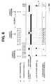
- FIGS. 7 and 8 show input passwords PW IN , permission signals S T , comparison outputs indicating comparison results of the checking section 302, and lock release signals S RL which are output from the lock controller 305.
- the horizontal axis represents time while solid segments of the comparison outputs and the lock release signals S RL represent active states and broken lines represent inactive states.
- permission is indicated by a high level.
- the permission signals S T of FIG. 8(b) are used as triggers and operations are effected at the rising edges of the triggers. While no password is input, the checking operation is not performed.
- the registered password PW REG is "6" and input of only passwords PW IN of "0" to "9" is accepted.
- the lock is released and the system 306 is allowed to operate as soon as the registered password PW REG of "6" is input.
- the checking section 302 detects coincidence. However, since no permission signal S T is generated, the lock release permitting section 304 does not permit lock release. Subsequently, passwords PW IN of "7” to "9" are sequentially input, so that the number of errors becomes 9 and the permission signal generation interval becomes “9.” Thereafter, the checking section 302 does not operate while no password input is made. Therefore, neither coincidence nor non-coincidence is detected and the permission signal generation interval is kept at "9.”
- the permission signal generation interval is minimum and permission signals S T rise consecutively at minimum intervals. If a registered password PW REG of "6" is input in this state, the lock is released immediately and the system 306 is allowed to operate.
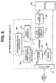
- the permission signal generator 107 or 307 may be constituted of the following components, for example.
- a reference oscillator 501 outputs a reference clock signal CLK to a counter 502.
- the counter 502 performs a counting operation in response to clock pulses of the reference clock signal CLK.
- a logic circuit 503 receives the outputs of the counter 502 and generates clock signals S T0 to S T2 of different cycles based on the count outputs of the counter 502.
- a counter 505 receives the non-coincidence signal from the checking section 103 or 302 and outputs the number N E of errors by counting the number of non-coincidence events. Further, the counter 505 receives the lock release signal S RL as a count reset signal from the lock controller 105 or 305.
- the lock release permission signal may be received from the lock release permitting section 304 in the embodiment as shown in FIG. 5.
- a selector 504 selects one of the clock signals S T0 to S T2 in accordance with the number N E of errors and outputs the selected one as a permission signal S T to the check permitting section 102 or the lock release permitting section 304.
- the logic circuit 503 consists of a NAND gate NAND1 having inverted outputs Q0 and Q1 of the counter 502 as inputs and another NAND gate NAND2 having inverted outputs Q1 and Q2 of the counter 502 as inputs.
- the NAND gates NAND1 and NAND2 output the clock signals S T1 and S T2 to the selector 504.
- An inverted output Q0 of the counter 502 is also supplied to the selector 504 as the clock signal S T0 .
- the counter 502 and the logic circuit 503 generate a plurality of clock signals S T0 to S T2 having different periods from the reference clock CLK.
- the selector 504 selects one of the clock signals S T0 to S T2 according to the number NE of errors which is counted by the counter 505.
- the non-coincidence signal which is one of two comparison results of the checking section 103 or 302, is supplied to the counter 505 as a clock signal.
- a signal for setting the permission signal generation interval at the minimum value such as a lock releasing signal S RL , is also supplied to the counter 505 as a reset signal. In this manner, the function of setting the permission signal generation interval at the minimum value when the comparison result is "coincidence" (step S204 in FIG. 2 or step S404 in FIG. 6) is realized.
- the selector 504 receives three kinds of waveforms S T0 to S T2 .
- a timing clock signal S T0 having a given cycle is selected as the permission signal S T .
- a frequency-halved timing clock signal S T1 is selected as the permission signal S T .
- a frequency-quartered timing signal S T2 is selected as the permission signal S T .
- the frequency or cycle of the permission signal S T is controlled in accordance with the number of events of non-coincidence in comparison results.
- the maximum countable number of errors is 3 because the counter 505 is a 2-bit counter.
- the countable number of errors can be increased by increasing the number of bits of the counter 505 and the kinds of signals generated by the counter 502 and the logic circuit 503, i.e., the kinds of different frequencies.
- N N is an integer
- frequency dividers having different divisors may be used to produce N clock signals S T0 -S TN having different frequencies.
- a selector selects one from the N clock signals as the permission signal S T .
- the circuit configuration of FIG. 9 can easily be implemented by using a known DSP (digital signal processor), a CPU (central processing unit), or the like.
- a processor (or a logic circuit) 506 may be used to control the selector 504 based on the number N E of errors.
- this configuration can accommodate a case where the number N E of errors exceeds an allowable range.
- the checking operation may be suspended when the number N E of errors exceeds an allowable range, for instance, 0 ⁇ N E ⁇ 8.
- the password is assumed to be a single-digit number for convenience of description, it is apparent that the invention can be applied to a case where the password is a number of two or more digits. In the latter case, the embodiments may be adapted such that the entire input password is compared with the entire password that is stored in advance in the memory.
- the check permitting section 102 as shown in FIG. 1 may be composed of delay flip-flop circuits which use the permission signal S T as a timing clock.
- the lock release permitting section 304 as shown in FIG. 5 may be composed of an AND gate inputting the permission signal S T and the comparison result.
- the configuration consisting of the check permitting section 102, the checking section 103, the lock controller 105 and the permission signal generator 107 may be implemented by a program-controlled processor (DSP or CPU).
- the configuration consisting of the checking section 302, the lock release permitting section 304, the lock controller 305 and the permission signal generator 307 may be implemented by a program-controlled processor (DSP or CPU).
- the interval between checking operations or the interval between lock release permitting operations is elongated in accordance with the number of events of non-coincidence in password comparison results.
Landscapes
- General Physics & Mathematics (AREA)
- Physics & Mathematics (AREA)
- Business, Economics & Management (AREA)
- Engineering & Computer Science (AREA)
- Accounting & Taxation (AREA)
- Theoretical Computer Science (AREA)
- Strategic Management (AREA)
- General Business, Economics & Management (AREA)
- Computer Networks & Wireless Communication (AREA)
- Microelectronics & Electronic Packaging (AREA)
- Computer Security & Cryptography (AREA)
- Finance (AREA)
- Storage Device Security (AREA)
- Financial Or Insurance-Related Operations Such As Payment And Settlement (AREA)
- Lock And Its Accessories (AREA)
Applications Claiming Priority (3)
| Application Number | Priority Date | Filing Date | Title |
|---|---|---|---|
| JP126184/96 | 1996-05-22 | ||
| JP12618496A JP2842377B2 (ja) | 1996-05-22 | 1996-05-22 | 暗証情報照合システム |
| JP12618496 | 1996-05-22 |
Publications (3)
| Publication Number | Publication Date |
|---|---|
| EP0809217A2 EP0809217A2 (en) | 1997-11-26 |
| EP0809217A3 EP0809217A3 (en) | 2001-01-31 |
| EP0809217B1 true EP0809217B1 (en) | 2002-10-02 |
Family
ID=14928776
Family Applications (1)
| Application Number | Title | Priority Date | Filing Date |
|---|---|---|---|
| EP97108297A Expired - Lifetime EP0809217B1 (en) | 1996-05-22 | 1997-05-22 | Secret information indentification system |
Country Status (5)
| Country | Link |
|---|---|
| US (1) | US5936543A (zh) |
| EP (1) | EP0809217B1 (zh) |
| JP (1) | JP2842377B2 (zh) |
| CN (1) | CN1133954C (zh) |
| DE (1) | DE69715965T2 (zh) |
Families Citing this family (11)
| Publication number | Priority date | Publication date | Assignee | Title |
|---|---|---|---|---|
| DE19941682A1 (de) * | 1999-09-01 | 2001-03-15 | Infineon Technologies Ag | Sicherheitsempfindliche Chipkarten |
| JP2001094550A (ja) | 1999-09-17 | 2001-04-06 | Toshiba Corp | 信号処理装置 |
| EP1413980A1 (en) * | 2002-10-24 | 2004-04-28 | SCHLUMBERGER Systèmes | Protection of a portable object against denial of service type attacks |
| JP2005190348A (ja) * | 2003-12-26 | 2005-07-14 | Fuji Xerox Co Ltd | 情報処理装置 |
| JP3998013B2 (ja) * | 2004-09-21 | 2007-10-24 | コニカミノルタビジネステクノロジーズ株式会社 | 命令処理装置の認証システム、画像形成装置、認証制御方法及び認証制御プログラム |
| WO2007107417A1 (en) * | 2006-03-23 | 2007-09-27 | International Business Machines Corporation | Method and systems for limiting repeated accesses to an electronic device |
| US8171543B2 (en) * | 2007-08-29 | 2012-05-01 | General Electric Company | Electronic trip units with limited read/write access |
| JP5125426B2 (ja) * | 2007-11-06 | 2013-01-23 | 沖電気工業株式会社 | 取引装置及び該取引装置における暗証番号処理方法 |
| JP4845057B2 (ja) * | 2008-04-14 | 2011-12-28 | 京セラ株式会社 | 携帯電子機器及びプログラム |
| JP5764075B2 (ja) * | 2012-01-06 | 2015-08-12 | ルネサスエレクトロニクス株式会社 | パスワード認証回路と方法 |
| JP2020189029A (ja) * | 2019-05-24 | 2020-11-26 | 日本宅配システム株式會社 | 物品収受システム |
Family Cites Families (6)
| Publication number | Priority date | Publication date | Assignee | Title |
|---|---|---|---|---|
| DE3041109A1 (de) * | 1980-10-31 | 1982-06-09 | GAO Gesellschaft für Automation und Organisation mbH, 8000 München | Identifikationselement |
| JPS592062B2 (ja) * | 1980-12-06 | 1984-01-17 | オムロン株式会社 | 取引処理装置における暗証コ−ド判別装置 |
| US4800590A (en) * | 1985-01-14 | 1989-01-24 | Willis E. Higgins | Computer key and computer lock system |
| US5657361A (en) * | 1994-09-06 | 1997-08-12 | Fujitsu Limited | Variant frequency detector circuit |
| JP2755183B2 (ja) * | 1994-09-26 | 1998-05-20 | 日本電気株式会社 | 低消費電力動作用のクロックジェネレータ/コントローラ内蔵lsi |
| US5594227A (en) * | 1995-03-28 | 1997-01-14 | Microsoft Corporation | System and method for protecting unauthorized access to data contents |
-
1996
- 1996-05-22 JP JP12618496A patent/JP2842377B2/ja not_active Expired - Fee Related
-
1997
- 1997-05-21 CN CNB971043272A patent/CN1133954C/zh not_active Expired - Fee Related
- 1997-05-22 EP EP97108297A patent/EP0809217B1/en not_active Expired - Lifetime
- 1997-05-22 DE DE69715965T patent/DE69715965T2/de not_active Expired - Fee Related
- 1997-05-22 US US08/861,612 patent/US5936543A/en not_active Expired - Fee Related
Also Published As
| Publication number | Publication date |
|---|---|
| JPH09311896A (ja) | 1997-12-02 |
| JP2842377B2 (ja) | 1999-01-06 |
| CN1179579A (zh) | 1998-04-22 |
| DE69715965T2 (de) | 2003-01-30 |
| US5936543A (en) | 1999-08-10 |
| EP0809217A2 (en) | 1997-11-26 |
| DE69715965D1 (de) | 2002-11-07 |
| CN1133954C (zh) | 2004-01-07 |
| EP0809217A3 (en) | 2001-01-31 |
Similar Documents
| Publication | Publication Date | Title |
|---|---|---|
| US4271482A (en) | Data processing system which protects the secrecy of confidential data | |
| US4439670A (en) | Method and device for the checking of the number of access attempts to an electronic store, notably that of an integrated circuit of an object such as a credit card or a buyer's card | |
| US4471216A (en) | System and process for identification of persons requesting access to particular facilities | |
| CA1245764A (en) | Identification system | |
| EP0029894B1 (en) | A system for achieving secure password verification | |
| US5083309A (en) | Method and a system enabling software to be run securely | |
| EP0809217B1 (en) | Secret information indentification system | |
| US4209782A (en) | Method and circuit arrangement for the electronically controlled release of door, safe and function locks using electronically coded keys | |
| EP0007002B1 (en) | Transaction terminal systems provided with potential user authentication | |
| US6304970B1 (en) | Hardware access control locking | |
| US6957338B1 (en) | Individual authentication system performing authentication in multiple steps | |
| US4904851A (en) | Identification authenticating system | |
| US5354975A (en) | Contactless data processing apparatus | |
| US5319765A (en) | Semiconductor memory unit utilizing a security code generator for selectively inhibiting memory access | |
| CN111414605B (zh) | 嵌入式安全单元的解锁方法、装置、电子设备及存储介质 | |
| KR20030005266A (ko) | 휴대 가능한 정보 기억 매체 및 그 인증 방법 | |
| US4912308A (en) | Device and method for effecting personal identification utilizing an IC card | |
| US11736294B2 (en) | Root-of-trust blockchain verification | |
| US7451485B2 (en) | Information processing unit having tamper-resistant system | |
| US5093861A (en) | Recognition apparatus and method for security systems | |
| US20080022119A1 (en) | Method and apparatus for preventing illegal access in electronic device | |
| EP3842981B1 (en) | Dynamic randomization of password challenge | |
| JP3756241B2 (ja) | メモリカード | |
| JPS5936860A (ja) | 不本意なデ−タ入力の識別方式 | |
| RU2231825C2 (ru) | Способ и устройство для эксплуатации многоступенчатого счетчика в одном направлении счета |
Legal Events
| Date | Code | Title | Description |
|---|---|---|---|
| PUAI | Public reference made under article 153(3) epc to a published international application that has entered the european phase |
Free format text: ORIGINAL CODE: 0009012 |
|
| AK | Designated contracting states |
Kind code of ref document: A2 Designated state(s): DE FR GB |
|
| PUAL | Search report despatched |
Free format text: ORIGINAL CODE: 0009013 |
|
| AK | Designated contracting states |
Kind code of ref document: A3 Designated state(s): DE FR GB |
|
| 17P | Request for examination filed |
Effective date: 20001221 |
|
| 17Q | First examination report despatched |
Effective date: 20010406 |
|
| GRAG | Despatch of communication of intention to grant |
Free format text: ORIGINAL CODE: EPIDOS AGRA |
|
| GRAG | Despatch of communication of intention to grant |
Free format text: ORIGINAL CODE: EPIDOS AGRA |
|
| GRAG | Despatch of communication of intention to grant |
Free format text: ORIGINAL CODE: EPIDOS AGRA |
|
| GRAH | Despatch of communication of intention to grant a patent |
Free format text: ORIGINAL CODE: EPIDOS IGRA |
|
| GRAH | Despatch of communication of intention to grant a patent |
Free format text: ORIGINAL CODE: EPIDOS IGRA |
|
| GRAA | (expected) grant |
Free format text: ORIGINAL CODE: 0009210 |
|
| AK | Designated contracting states |
Kind code of ref document: B1 Designated state(s): DE FR GB |
|
| REG | Reference to a national code |
Ref country code: GB Ref legal event code: FG4D |
|
| REF | Corresponds to: |
Ref document number: 69715965 Country of ref document: DE Date of ref document: 20021107 |
|
| ET | Fr: translation filed | ||
| PLBE | No opposition filed within time limit |
Free format text: ORIGINAL CODE: 0009261 |
|
| STAA | Information on the status of an ep patent application or granted ep patent |
Free format text: STATUS: NO OPPOSITION FILED WITHIN TIME LIMIT |
|
| 26N | No opposition filed |
Effective date: 20030703 |
|
| PGFP | Annual fee paid to national office [announced via postgrant information from national office to epo] |
Ref country code: FR Payment date: 20090515 Year of fee payment: 13 Ref country code: DE Payment date: 20090514 Year of fee payment: 13 |
|
| PGFP | Annual fee paid to national office [announced via postgrant information from national office to epo] |
Ref country code: GB Payment date: 20100329 Year of fee payment: 14 |
|
| REG | Reference to a national code |
Ref country code: FR Ref legal event code: ST Effective date: 20110131 |
|
| PG25 | Lapsed in a contracting state [announced via postgrant information from national office to epo] |
Ref country code: DE Free format text: LAPSE BECAUSE OF NON-PAYMENT OF DUE FEES Effective date: 20101201 |
|
| PG25 | Lapsed in a contracting state [announced via postgrant information from national office to epo] |
Ref country code: FR Free format text: LAPSE BECAUSE OF NON-PAYMENT OF DUE FEES Effective date: 20100531 |
|
| GBPC | Gb: european patent ceased through non-payment of renewal fee |
Effective date: 20110522 |
|
| PG25 | Lapsed in a contracting state [announced via postgrant information from national office to epo] |
Ref country code: GB Free format text: LAPSE BECAUSE OF NON-PAYMENT OF DUE FEES Effective date: 20110522 |