EP0809059B1 - Dichtung eines Ventilshafts - Google Patents
Dichtung eines Ventilshafts Download PDFInfo
- Publication number
- EP0809059B1 EP0809059B1 EP19970107617 EP97107617A EP0809059B1 EP 0809059 B1 EP0809059 B1 EP 0809059B1 EP 19970107617 EP19970107617 EP 19970107617 EP 97107617 A EP97107617 A EP 97107617A EP 0809059 B1 EP0809059 B1 EP 0809059B1
- Authority
- EP
- European Patent Office
- Prior art keywords
- sealing element
- valve arrangement
- stem
- housing
- lining
- Prior art date
- Legal status (The legal status is an assumption and is not a legal conclusion. Google has not performed a legal analysis and makes no representation as to the accuracy of the status listed.)
- Expired - Lifetime
Links
- 238000007789 sealing Methods 0.000 title claims description 72
- 238000012856 packing Methods 0.000 claims abstract description 8
- 229920001343 polytetrafluoroethylene Polymers 0.000 claims abstract description 7
- 239000004810 polytetrafluoroethylene Substances 0.000 claims abstract description 7
- 238000000576 coating method Methods 0.000 claims description 31
- 239000011248 coating agent Substances 0.000 claims description 30
- 239000004033 plastic Substances 0.000 abstract description 6
- -1 polytetrafluoroethylene Polymers 0.000 abstract description 2
- 238000005253 cladding Methods 0.000 abstract 1
- 210000004907 gland Anatomy 0.000 description 7
- 239000011521 glass Substances 0.000 description 6
- 238000004519 manufacturing process Methods 0.000 description 6
- 238000013459 approach Methods 0.000 description 5
- 238000013461 design Methods 0.000 description 5
- 229920001774 Perfluoroether Polymers 0.000 description 3
- 230000036316 preload Effects 0.000 description 3
- 230000005540 biological transmission Effects 0.000 description 2
- 238000010276 construction Methods 0.000 description 2
- 230000008878 coupling Effects 0.000 description 2
- 238000010168 coupling process Methods 0.000 description 2
- 238000005859 coupling reaction Methods 0.000 description 2
- 239000006223 plastic coating Substances 0.000 description 2
- 238000005299 abrasion Methods 0.000 description 1
- 230000000712 assembly Effects 0.000 description 1
- 238000000429 assembly Methods 0.000 description 1
- 230000004323 axial length Effects 0.000 description 1
- 230000000903 blocking effect Effects 0.000 description 1
- 238000011161 development Methods 0.000 description 1
- 230000018109 developmental process Effects 0.000 description 1
- 238000005553 drilling Methods 0.000 description 1
- 230000000694 effects Effects 0.000 description 1
- 230000007613 environmental effect Effects 0.000 description 1
- 239000004744 fabric Substances 0.000 description 1
- MSKQYWJTFPOQAV-UHFFFAOYSA-N fluoroethene;prop-1-ene Chemical group CC=C.FC=C MSKQYWJTFPOQAV-UHFFFAOYSA-N 0.000 description 1
- 238000009434 installation Methods 0.000 description 1
- 238000012544 monitoring process Methods 0.000 description 1
- 230000035515 penetration Effects 0.000 description 1
- 239000000126 substance Substances 0.000 description 1
- 238000012549 training Methods 0.000 description 1
- 238000012546 transfer Methods 0.000 description 1
Images

Classifications
-
- F—MECHANICAL ENGINEERING; LIGHTING; HEATING; WEAPONS; BLASTING
- F16—ENGINEERING ELEMENTS AND UNITS; GENERAL MEASURES FOR PRODUCING AND MAINTAINING EFFECTIVE FUNCTIONING OF MACHINES OR INSTALLATIONS; THERMAL INSULATION IN GENERAL
- F16K—VALVES; TAPS; COCKS; ACTUATING-FLOATS; DEVICES FOR VENTING OR AERATING
- F16K41/00—Spindle sealings
- F16K41/02—Spindle sealings with stuffing-box ; Sealing rings
- F16K41/023—Spindle sealings with stuffing-box ; Sealing rings for spindles which only rotate, i.e. non-rising spindles
- F16K41/026—Spindle sealings with stuffing-box ; Sealing rings for spindles which only rotate, i.e. non-rising spindles for rotating valves
-
- F—MECHANICAL ENGINEERING; LIGHTING; HEATING; WEAPONS; BLASTING
- F16—ENGINEERING ELEMENTS AND UNITS; GENERAL MEASURES FOR PRODUCING AND MAINTAINING EFFECTIVE FUNCTIONING OF MACHINES OR INSTALLATIONS; THERMAL INSULATION IN GENERAL
- F16K—VALVES; TAPS; COCKS; ACTUATING-FLOATS; DEVICES FOR VENTING OR AERATING
- F16K5/00—Plug valves; Taps or cocks comprising only cut-off apparatus having at least one of the sealing faces shaped as a more or less complete surface of a solid of revolution, the opening and closing movement being predominantly rotary
- F16K5/06—Plug valves; Taps or cocks comprising only cut-off apparatus having at least one of the sealing faces shaped as a more or less complete surface of a solid of revolution, the opening and closing movement being predominantly rotary with plugs having spherical surfaces; Packings therefor
- F16K5/0657—Particular coverings or materials
-
- Y—GENERAL TAGGING OF NEW TECHNOLOGICAL DEVELOPMENTS; GENERAL TAGGING OF CROSS-SECTIONAL TECHNOLOGIES SPANNING OVER SEVERAL SECTIONS OF THE IPC; TECHNICAL SUBJECTS COVERED BY FORMER USPC CROSS-REFERENCE ART COLLECTIONS [XRACs] AND DIGESTS
- Y10—TECHNICAL SUBJECTS COVERED BY FORMER USPC
- Y10T—TECHNICAL SUBJECTS COVERED BY FORMER US CLASSIFICATION
- Y10T137/00—Fluid handling
- Y10T137/6851—With casing, support, protector or static constructional installations
- Y10T137/7036—Jacketed
Definitions
- the invention relates to a valve arrangement according to the in the preamble of Features specified claim 1.
- Such a valve arrangement is known from DE 1 288 392 and contains in a housing a shut-off element rotatably arranged by means of a shaft.
- the housing is inside with a Provided lining and the shaft has a coating, being in a surrounding the shaft Annular space is arranged a sealing element.
- the housing consists of the previously known Valve arrangement of three interconnected housing parts, the middle housing part contains a nozzle through which the shaft is guided to the outside.
- the third, middle one Housing part requires an additional compared to a two-part housing design Effort, especially with regard to the installation of the necessary lining.
- FR 2 412 017 From FR 2 412 017 is a valve arrangement with a one-piece housing without Lining known, which has a sleeve at one axial end in an enlarged interior contains for the axial fixing of the shut-off element designed as a ball.
- an annular body At the housing connection radially outward then an annular body is arranged, which has a spring, bearing elements and locking means for an extension body of the shaft to initiate the Contains rotary movement on the shut-off element.
- the ring body not only has a significant one Length, but is a necessary part of the valve assembly, which without the same is not functional.
- US Pat. No. 4,930,748 describes a valve arrangement designed as a shut-off and control valve known, the blocking element designed as a chick with a shaft rotatably connected and rotatably arranged in a housing, wherein for sealing the shaft in Area of a housing cover, two sealing elements are provided.
- the first sealing element is supported on an underside of the lid on the inside of the housing, while the second sealing element is assigned to the outside and can be adjusted from the outside if necessary is. Due to the design of the shut-off element as a chick, the axial position of the Shaft due to manufacturing tolerances, abrasion, external forces or the like yourself change.
- first sealing element By supporting the inner, first sealing element on the washer becomes a reliable, independent of the axial position of the shaft Seal reached.
- the increased safety regulations and regulations for environmental protection is complied with and the required limit values for lecrates are met for one long service life maintained.
- This valve arrangement is for special applications and areas of application and requires a not inconsiderable manufacturing effort.
- fittings with linings are used today or coatings made of plastic, in particular made of PTFE (Polytetrafluoroethylene), FEP (fluoroethylene propylene), or PFA (perfluoroalkoxy).
- PTFE Polytetrafluoroethylene
- FEP fluoroethylene propylene
- PFA perfluoroalkoxy
- a valve arrangement is from German utility model DE 89 10 895 U 1 known, which is designed as a ball valve.
- the housing and also the shut-off ball are provided with a plastic coating.
- On the rotatable in the housing arranged ball is integrally formed on a shaft, which from the housing is guided on the outside and is surrounded by a special stuffing box housing.
- a sealing element is arranged, which by means of a Spring is applied.
- the additional stuffing box housing is partly outside the Housing the valve assembly arranged and protrudes with another part in it Inside of the housing mentioned up to the ball.
- the gland housing with a plastic coating provided, whereby a considerable manufacturing effort is required.
- German utility model DE 84 31 238 U 1 describes a retrofittable double stuffing box arrangement known for a ball valve. It is an extension piece provided with a lower plate, a tube and an upper mounting plate, being a spindle extension in said comparatively long tube is arranged. The tube and the two plates are welded together connected. Furthermore, this arrangement has no coating or lining and is for the Use under high security requirements is not readily suitable.
- a gland packing is from the German patent DE 40 16 541 C 2 known which active and passive sealing rings in one recording having.
- the passive gland rings are for the transmission of axial forces formed and lie alternately with their radial inner surface on the shaft or with its radial outer surface on the wall of the receptacle for the gland seal on.
- a lining or coating is not provided.
- the invention is based on the object of a valve arrangement mentioned type with little constructive effort to the effect that the Lekrates can be minimized and high security requirements, in particular according to TA-Luft.
- the valve arrangement is intended to provide a high level of functional reliability and have a long service life, and the replacement or replacement of the elements should be feasible without any problems.
- the proposed valve arrangement is characterized by a simple and nevertheless functional construction.
- the valve arrangement equipped with a single or a double shaft seal.
- the double shaft seal expediently enables leakage monitoring or pressure overlay for increased tightness requirements to the outside or to the atmosphere.
- Adapted sealing systems arrive at the tightness to the atmosphere uniform basic design for use.
- the housing and shaft are for both embodiments are the same, and a double number of the rather expensive lining tools omitted for housing and shaft.
- valve assemblies that have already been assembled can also be retrofitted to the customer can be converted.
- the embodiment with a double sealing system is in their height compared to the embodiment with a simple sealing system only slightly enlarged.
- connection dimensions for the drive assembly and the like remain unchanged, so that matching attachments such as bridges and coupling and actuators, such as levers or the like.
- matching attachments such as bridges and coupling and actuators, such as levers or the like.
- the one or more sealing elements are arranged directly in the housing or the ring body and lie with their radial outer surfaces directly on the lining of the Housing or the ring body.
- the inner diameter of the ring body liner is suitably the same size as the inner diameter of the lining of the bore Housing for the sealing element.
- valve arrangement is described below using a ball valve explained in more detail, but this does not limit the invention. So it can Valve arrangement as a cock with a conical plug, as a rotary plug valve or as Flap with a flap disc or similar be trained. It is crucial for all embodiments the valve arrangement that optional sealing systems for different Requirements are used while the other components, and especially the plastic-lined housing and the plastic-coated one Shaft, are used consistently.
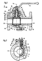
- the ball valve shown in Fig. 1 has a divided housing with two housing parts 2, 4, which are connected to one another by means of screws 6.
- a shut-off element 8 which according to the drawing has a recess 9 above and here is formed as a ball
- a shaft 10 is rotatably connected.
- the shaft 10 has a projection 11 engaging in the recess, which corresponds to the Recess 9 is formed.
- the recess 9 and the approach 11 thus form Coupling means for torque transmission.
- the recess 9 is useful as Slit formed in which the preferably plate-shaped extension 11 of the shaft intervenes.
- the housing parts 2, 4 each contain a flange 16, 18 for connection to one here Pipe not shown.
- the housing parts 2, 4 are inside and also in Area of the flanges 16, 18, ie in the medium-carrying areas, with a lining 20, 21 provided, which in particular made of plastic, such as PTFE, FEP or PFA consists.
- the shut-off element 8 is also provided with a corresponding coating 22 Mistake.
- the shaft 10 also has such a coating 24.
- the proposed valve arrangement is therefore expediently a lined one or coated embodiment, and thus it corresponds to higher Temperatures and pressures meet the security requirements for corrosive and aggressive Flow media.
- sealing rings 26, 28 are provided in a known manner.
- the shaft 10 is in a recess or bore 30 in the first housing part 2 used, and this bore 30 is provided with the lining 20.
- a first sealing element 32 is provided, which on Shaft 10 or its coating 24 lies sealingly. With this first Sealing element 32 becomes a simple, basic seal in the area of Shaft penetration reached to the outside.
- the first is expedient Sealing element 32 as a normal packing, in particular as a PTFE packing educated.
- the first sealing element 32 is located within a nozzle 34 of the first housing part 2, namely in an enlarged annular space which between the middle cylindrical part of the shaft 10 and the nozzle 34 is present.
- the Sealing element 32 is located radially outside directly on the lining 20 of the recess or bore 30 of the housing 2 or its socket 34.
- the said annulus ends in the direction of the shut-off element 8 at a step 36 at which the first Sealing element 32 is supported.
- An annular body 38 adjoins the axial end face of the connector 34, the inner surface of which just as that of the connector 34 is provided with a lining 40.
- the Lining 40 has its axial length and / or the total length of the Ring body 38 expediently has a constant inner diameter 41 on.
- the inner diameter 41 is essentially the same size as the inner diameter the lining 20 of the socket 34.
- the second sealing element 42 is located radially outside directly on the inner surface of the inner liner 40 and, on the other hand, radially inside on the shaft 10, namely the coating 24 on.
- the end face of the nozzle 34 and the axially opposite contact surface of the Ring body 38 contain coaxial and mutually corresponding steps or Collars 44, 46 such that the ring body 38 is arranged coaxially with the axis of rotation 14 is.
- the second sealing element 42 arranged in the area of the ring body 38 in combination with the first sealing element 32, the improved and increased Sealing of the shaft 10 in accordance with safety requirements the second sealing element 42 from the outside associated bush 48 expediently the common pressing and prestressing of the two in Direction of action connected sealing elements 32 and 42, between which is preferably provided a ring 49 in the axial direction.
- a stop 50 is provided, which is attached to the ring body 38.
- the ring body 38 has for the stop 50 a step 52, which is formed in accordance with the step 44 of the nozzle 34 is.
- the annular body 38 axially adjoining the connecting piece 34 and extending it also contains a lateral bore 54, which by means of a screw 56 on the Is tightly closable on the outside.
- the bore 54 opens preferably inside Area of the ring 49 between the two sealing elements 32, 34 and enables one Checking or checking the sealing function. Unless an increased pressure or medium in the intermediate space, that is to say in the pressure direction behind the first sealing element 32 revision measures are pending.
- the second sealing element 42 ensures that even in this case, an escape of flowing medium in the Outside space is prevented in view of the increased security requirements.
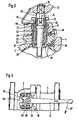
- Fig. 2 shows partly in an axial view and partly in section the ball valve with the ring body 38 and the socket 48, which act as glasses for generating the axial Preload is formed on the two sealing elements 32 and 42.
- a bolt 58 is the bushing or packing gland 48 in the socket 34 of the first housing part 2 fixed.
- the bolts 58 contain a hexagon, preferably Stop 60, which on the one hand screwing the screws 56 into the Stub 34 allows and which on the other hand, the defined definition of the ring body 38 with respect to the housing part 2.
- the bolts 58 penetrate with the upper ends of holes in the glasses 48, which are adjustable by means of adjustable nuts 62 is thus adjustable in the direction of the axis of rotation 14.
- the glasses 48 surround one small annular gap an extension portion 64 of the shaft 10.
- the extension part 64 contains a pin protruding from the top of the glasses 48 66, which is designed in particular as a square and which for the rotationally fixed connection is formed with the handle or actuator mentioned.
- the cone 66 is correspondingly provided with a pin, preferably square 68, which engages in a corresponding recess 70 of the extension body.
- the recess 9 of the shut-off element 8 and the corresponding one and in the recess 9 engaging approach 11 of the shaft 10 are clearly visible.
- the slot-shaped recess 9 extends transversely to the axis of the flow opening 71.
- the axis of the flow opening 71 which according to the drawing is orthogonal to the drawing plane stands, is orthogonal to the slot-shaped recess 9 and the plate-shaped Approach 11 arranged.
- the width of the plate or lug 11 and also that Width of the recess 9 are larger than the diameter of the shaft 10. It will expressly stated that the shaft 10 with the approach 11 with the coating 24 is provided.
- This coating 24 is in a particularly expedient manner in the radial Direction at least as far out that the second sealing element 42 on the coating 24 is applied.
- shut-off element and shaft can also be formed in one piece.
- Extension body 64 of very special importance to the following on hand 5 and 6 illustrated embodiment with only a single sealing element to be able to realize.
- the shaft has a uniform for both embodiments Length on. But also in the two-part construction of shut-off element explained so far and shaft is the uniform design and length specification of the shaft 10 of particular importance, especially since only one tool for manufacturing and Arrangement of the coating 24 on the shaft 10 is required. On the other hand in the context of the invention, however, such configurations with two different long shafts.
- the longer shaft shows the total length of the shaft and Extension body according to Figure 2. For the embodiment with only one sealing element however, only the short shaft according to FIG. 2 is used.
- FIG 3 shows an enlarged view of the upper part of the valve arrangement in the area of the stem 10 with the extension body 64 and part of the handle 12.
- the thickness of the disk or of the shoulder 11 is smaller than the diameter of the cylindrical pin 10.
- the corresponding recess of the not here Shut-off elements shown has a thickness smaller than the shaft diameter.
- annular gap between the extension piece 64 and the Socket 48 is provided with an inner socket 72.
- This socket 72 serves in expediently for the radial guidance of the extension body 64, so that undesirable forces on the shaft 10 and / or that not shown here Shut-off element can be avoided.
- the inner socket 72 serves as part of the Invention further as the lining of the socket 48.
- the socket 72 further includes an enlarged part 73, which rests on the second sealing element 42. On the widened part 73, the axial adjusting or prestressing forces are exerted on the glasses 48 the sealing elements 42, 32 transmitted.
- the shaft coating 24 extends in the radial direction into the area of the second sealing element 42.
- the Coating 24 ends at an annular collar 77 of the shaft 10.
- the outer diameter of the collar 77 is preferably substantially the same size as the outer diameter the coating 24.
- the second seal 42 is partially in contact of the coating 24 and partly also on the annular collar 77, the seal 42 has the same diameter throughout in the axial direction.
- the coating 24 has a radial flange 78, the outer diameter of which is larger than the outer diameter of the by a predetermined amount Coating in the area of the described seals 32 and 42.
- the flange 78 lies with its top surface according to the drawing on the lining 20 of the housing 2 or whose level is 36.
- an axial is particularly expedient Securing of the pin 10 ensured, if necessary within the flange 78th can also have a flange. Since the flange 78 of the coating 24th just as the lining 20 are preferably made of plastic Friction losses reduced to a minimum.
- the extension body 64 includes a central bore 74 through which a Screw 76 is passed and with its lower end in an internal thread of the Shank 10 or the pin 68 is screwed.
- This screw 76 is used the non-rotatable connection of both the handle 12 and the extension body 64 with the shaft 10.
- the bushing 48 by axially adjusting the bushing 48 the bias of the two connected in series in the direction of action Sealing elements 32 and 42 are defined.
- FIG. 4 shows a top view of the ball valve with the two housing parts 2, 4 and the ring body 38, which is connected to the nozzle via the two screw bolts 58 of the housing part 2 is connected.
- the fabric bushing eyeglasses 48 are held by the nuts 62 set to preset the bias of the sealing elements explained.
- the handle 12 has two projections 79, 80 corresponding to the stop 50 and can can thus be pivoted in the direction of arrow 82, the ball 8 being shown in FIG. 1 open position shown is pivoted into the shut-off position.
- FIG. 5 and 6 show an embodiment of the ball valve corresponding to the ball valve 1 and 2.
- the housing parts 2, 4 and also the shaft 10 are with the Embodiment described at the outset is identical, and so is the first Sealing element 32 in the socket 34 of the housing part 2.
- the handle 12 is in this embodiment directly connected to the shaft 10, the illustrated extension body, the Ring body and the second sealing element are omitted.
- the socket or packing gland 48 is again the same as in the first embodiment, but immediately with connected to the housing.
- the ring collar 77 projects partially in this embodiment Socket 28 into it.
- the coating 24 also extends from the inside in the socket 28 into it. A reliable radial guidance of the shaft 10 is thus guaranteed.
- the linings 20, 21 of the two housing parts 2, 4 were also manufactured with the same tools as for the two housing parts of the first embodiment.
- the stop 50 is on the step 44 of the nozzle 34 in its rotational position secured, the stage 44 is designed and arranged in accordance with how the 1 for the annular body provided there.
- the based 5 and 6 embodiment has a simple shaft seal in Shape of the first sealing element 32, but are the essential components, such as in particular the housing parts 2, 4, the shaft 10, also the first sealing element 32, the glasses 48, the stop 50 and the handle 12 in accordance with the first embodiment educated.
Landscapes
- Engineering & Computer Science (AREA)
- General Engineering & Computer Science (AREA)
- Mechanical Engineering (AREA)
- Taps Or Cocks (AREA)
- Lift Valve (AREA)
- Joints Allowing Movement (AREA)
- Details Of Valves (AREA)
- Valve Housings (AREA)
- Sealing With Elastic Sealing Lips (AREA)
Description
- Fig. 1
- einen axialen Schnitt eines Kugelhahns mit doppelter Schaftabdichtung,
- Fig. 2
- teilweise geschnitten bzw. teilweise in einer axialen Ansicht den Kugelhahn in Blickrichtung II gemäß Fig. 1,
- Fig. 3
- vergrößert den Bereich des Schaftes des Kugelhahns gemäß Fig. 1,
- Fig. 4
- eine Aufsicht auf den Kugelhahn,
- Fig. 5
- eine Ausführungsform des Kugelhahns gemäß Fig. 1, jedoch mit einfacher Schaftabdichtung,
- Fig. 6
- teilweise geschnitten bzw. teilweise in einer axialen Ansicht in Blickrichtung VI den Kugelhahn gemäß Fig. 5.
- 2, 4
- Gehäuseteil
- 6
- Schraube
- 8
- Absperrelement/Kugel
- 9
- Ausnehmung
- 10
- Schaft
- 11
- Ansatz
- 12
- Handgriff
- 14
- Drehachse
- 16, 18
- Flansch
- 20, 21
- Auskleidung von 2, 4
- 22
- Beschichtung von 8
- 24
- Beschichtung von 10
- 26, 28
- Dichtring
- 30
- Bohrung
- 32
- erstes Dichtelement
- 34
- Stutzen von 2
- 36
- Stufe
- 38
- Ringkörper
- 40
- Auskleidung von 38
- 41
- Innendurchmesser von 40
- 42
- zweites Dichtelement
- 44, 46
- Stufe, Ringbund
- 48
- Buchse/Brille
- 49
- Ring
- 50
- Anschlag
- 52
- Stufe von 38
- 54
- Bohrung in 38
- 56
- Schraube
- 58
- Schraubbolzen
- 60
- Anschlag
- 62
- Mutter
- 64
- Verlängerungskörper
- 66
- Zapfen/Vierkant von 64
- 68
- Zapfen/Vierkant von 10
- 70
- Ausnehmung in 64
- 71
- Durchflußöffnung
- 72
- innere Buchse
- 73
- erweiterter Teil
- 74
- zentrale Bohrung in 48
- 76
- Schraube
- 77
- Ringbund
- 78
- Flansch
- 79, 80
- Vorsprung
- 82
- Pfeil
Claims (13)
- Ventilanordnung mit einem Gehäuse, welches zwei eine Auskleidung (20, 21) aufweisende Gehäuseteile (2, 4) aufweist, mit einem im Gehäuse (2, 4) drehbar angeordneten Absperrelement (8), mit einem eine Beschichtung (24) aufweisenden Schaft (10), welcher mit dem Absperrelement (8) zum Drehen desselben gekoppelt ist und welcher durch einen Stutzen (34) durch das Gehäuse nach außen geführt ist, und mit einem ersten Dichtelement (32), welches unmittelbar in einem den Schaft (10) umgebenden Ringraum angeordnet ist, welcher in Richtung zum Absperrelement (8) an einer Stufe (36) zum Abstützen des ersten Dichtelements (32) endet,
wobei mittels einer Buchse (48), welche mit dem Stutzen (34) verbunden und in Richtung der Drehachse (14) des Schafts (10) bewegbar ist, das erste Dichtelement (32) vorspannbar ist und wobei die Beschichtung (24) einen Flansch (78) aufweist,
wobei der Stutzen (34) Bestandteil des einen Gehäuseteiles (2) ist, wobei das erste Dichtelement (32) an der in den Stutzen (34) reichenden Auskleidung (20) des einen Gehäuseteils (2) anliegt, daß der Flansch (78) der Beschichtung (24) des Schaftes (10) mit einer dem Absperrelement (8) abgewandten oberen Fläche an der Auskleidung (20) des Gehäuseteils (2) anliegt, dadurch gekennzeichnet, daß die Ventilanordnung derart gestaltet ist,
daß wahlweise eine einfache Schaftabdichtung, enthaltend das erste Dichtelement (32), vorgesehen sein kann oder eine doppelte Schaftabdichtung, enthaltend das erste Dichtelement (32) und ein zweites Dichtelement (42) vorgesehen sein kann,
wobei in der Ausführungsform mit der doppelten Schaftabdichtung ein Ringkörper (38) in Richtung der Drehachse (14) an dem Stutzen (34) des Gehäuses (2) nach außen axial anschließend angeordnet ist und das zweite Dichtelement (42) zumindest teilweise in dem Ringkörper (38) angeordnet ist und an der Beschichtung (24) des Schaftes (10) anliegt und ferner mit dem Schaft (10) ein Verlängerungskörper (24) drehfest verbunden ist, über welchen auf den Schaft (10) und somit das Absperrelement (8) eine Drehbewegung einleitbar ist
und daß die Buchse (48), mittels welcher das erste Dichtelement (32) und wahlweise das zweite Dichtelement (48) vorspannbar ist, mittels Schraubbolzen (58) im Stutzen (34) des Gehäuseteils (2) fixiert ist. - Ventilanordnung nach Anspruch 1, dadurch gekennzeichnet, daß der Ringkörper (38) zumindest im Bereich des zweiten Dichtelements (42) eine Auskleidung (40) aufweist und/oder daß der Innendurchmesser (41) der Auskleidung (40) des Ringkörpers (38) zumindest näherungsweise gleich groß ist wie der Innendurchmesser der Auskleidung (20) in der Bohrung (30) des Stutzens (34) des Gehäuseteils (2).
- Ventilanordnung nach Anspruch 1 oder 2, dadurch gekennzeichnet, daß die Beschichtung (24) des Schaftes (10) sich in Richtung der Drehachse (14) durchgehend vom Gehäuseinneren bis zu dem zweiten Dichtelement (42) erstreckt.
- Ventilanordnung nach Anspruch 2 oder 3, dadurch gekennzeichnet, daß die Auskleidung (40) des Ringkörpers (38) axial im Anschluß an die Auskleidung (20) innerhalb des Stutzens (34) angeordnet ist.
- Ventilanordnung nach einem der Ansprüche 1 bis 4, dadurch gekennzeichnet, daß der Außendurchmesser des Flansches (78) um einen vorgegebenen Betrag größer ist als der Außendurchmesser der Beschichtung (24) des Schaftes (10) im Bereich des ersten Dichtelements (32).
- Ventilanordnung nach einem der Ansprüche 1 bis 5, dadurch gekennzeichnet, daß der Ringkörper (38) eine Bohrung (54) aufweist, welche radial innen, vorzugsweise im Bereich zwischen den beiden Dichtelementen (32, 42) endet und welche außen, vorzugsweise mittels einer Schraube (56), dicht verschließbar ist, und/oder daß die Auskleidung (40) des Ringkörpers (38) über die Gesamtlänge einen im wesentlichen konstanten Innendurchmesser (41) aufweist.
- Ventilanordnung nach einem der Ansprüche 1 bis 6, dadurch gekennzeichnet, daß der Verlängerungskörper (64) eine Ausnehmung (70) aufweist, in welche ein korrespondierend ausgebildeter Zapfen (68) des Schaftes (10) eingreift, und daß der Verlängerungskörper (64) am oberen Ende, insbesondere zur drehfesten Verbindung mit einem Handgriff (12), einen weiteren Zapfen (66) aufweist, welcher entsprechend dem Zapfen (68) des Schaftes (10) ausgebildet ist.
- Ventilanordnung nach einem der Ansprüche 1 bis 7, dadurch gekennzeichnet, daß die beiden Dichtelemente (32, 42) zumindest näherungsweise übereinstimmend ausgebildet sind und/oder als Packungen, insbesondere als PTFE-Packungen, ausgebildet sind.
- Ventilanordnung nach einem der Ansprüche 1 bis 8, dadurch gekennzeichnet, daß axial zwischen dem ersten Dichtetement (32) und dem zweiten Dichtelement (42) ein Ring (49) angeordnet ist.
- Ventilanordnung nach einem der Ansprüche 1 bis 9, dadurch gekennzeichnet, daß zwischen dem Verlängerungskörper (64) und der Buchse (48) eine innere Buchse (72) vorgesehen ist und/oder daß die innere Buchse (72) als eine Auskleidung der Buchse (48) ausgebildet ist und/oder daß die innere Buchse (72) einen erweiterten Teil (73) aufweist, an welchem das zweite Dichtelement (42) anliegt.
- Ventilanordnung nach einem der Ansprüche 1 bis 10, dadurch gekennzeichnet, daß die Beschichtung (24) an einem Ringbund (77) des Schaftes (10) endet und/oder daß der Außendurchmesser des Ringbundes (77) im wesentlichen gleich groß ist wie der Außendurchmesser der Beschichtung (24).
- Ventilanordnung nach Anspruch 11, dadurch gekennzeichnet, daß der Ringbund (77) teilweise in die Buchse (48) hineinragt.
- Ventilanordnung nach Anspruch 11 oder 12, dadurch gekennzeichnet, daß in der zweiten Ausführungsform das zweite Dichtelement (42) teilweise am Ringbund (77) anliegt.
Applications Claiming Priority (2)
| Application Number | Priority Date | Filing Date | Title |
|---|---|---|---|
| DE1996120694 DE19620694C2 (de) | 1996-05-22 | 1996-05-22 | Ventilanordnung |
| DE19620694 | 1996-05-22 |
Publications (3)
| Publication Number | Publication Date |
|---|---|
| EP0809059A2 EP0809059A2 (de) | 1997-11-26 |
| EP0809059A3 EP0809059A3 (de) | 1998-05-13 |
| EP0809059B1 true EP0809059B1 (de) | 2002-12-18 |
Family
ID=7795070
Family Applications (1)
| Application Number | Title | Priority Date | Filing Date |
|---|---|---|---|
| EP19970107617 Expired - Lifetime EP0809059B1 (de) | 1996-05-22 | 1997-05-09 | Dichtung eines Ventilshafts |
Country Status (9)
| Country | Link |
|---|---|
| US (1) | US5979491A (de) |
| EP (1) | EP0809059B1 (de) |
| JP (1) | JPH1047505A (de) |
| KR (1) | KR970075604A (de) |
| CN (1) | CN1081768C (de) |
| AT (1) | ATE230083T1 (de) |
| BR (1) | BR9704226A (de) |
| CA (1) | CA2206953C (de) |
| DE (2) | DE19620694C2 (de) |
Cited By (2)
| Publication number | Priority date | Publication date | Assignee | Title |
|---|---|---|---|---|
| KR970075604A (ko) * | 1996-05-22 | 1997-12-10 | 곤지오르 볼프강 | 밸브 구조 |
| DE202008011406U1 (de) | 2007-12-20 | 2009-06-18 | Xomox International Gmbh & Co | Ventil |
Families Citing this family (40)
| Publication number | Priority date | Publication date | Assignee | Title |
|---|---|---|---|---|
| US7017915B2 (en) * | 2001-10-03 | 2006-03-28 | Metso Automation Usa Inc. | Stem or shaft seal arrangement |
| KR100423556B1 (ko) * | 2003-03-10 | 2004-03-18 | 주식회사 비엠티 | 볼밸브 |
| US7048254B2 (en) | 2003-06-19 | 2006-05-23 | Giant Industries | Low-leakage valve apparatus |
| US20050173002A1 (en) * | 2003-11-05 | 2005-08-11 | Simendinger William H. | Fiber-reinforced polymer (FRP) valve body with a polymeric liner and method of manufacturing same |
| US7628380B1 (en) | 2005-10-11 | 2009-12-08 | Pureflex, Inc. | Self-compensating packing gland |
| EP2150737B1 (de) * | 2007-05-24 | 2011-07-20 | Michael Tappe | Kugelventil aus kunststoff |
| DE102008027888A1 (de) * | 2008-06-11 | 2009-12-17 | Apel, Helga | Drosselklappenstutzen mit Drosselklappe |
| US20110017931A1 (en) * | 2009-07-24 | 2011-01-27 | Chih-Hsin Lee | Ball valve |
| GB2493180A (en) * | 2011-07-27 | 2013-01-30 | Expro North Sea Ltd | Valve housing arrangement |
| US9512926B2 (en) * | 2011-10-27 | 2016-12-06 | Aegis Flow Technologies, L.L.C. | Butterfly valve and stem sealing assembly |
| US8910921B2 (en) * | 2011-10-27 | 2014-12-16 | Aegis Flow Technologies, L.L.C. | Valve and stem sealing assembly |
| CN103807458B (zh) * | 2014-02-19 | 2016-04-27 | 盐城市圣泰阀门有限公司 | 一种加氢阀及其加工方法 |
| DE102016000081A1 (de) * | 2016-01-07 | 2017-07-13 | Richter Chemie-Technik Gmbh | Bodenarmatur eines mobilen Tanks |
| BE1024257B1 (nl) * | 2016-06-03 | 2018-01-15 | Inno-Mould Nv | Corrosiebestendig kogelkraan |
| US10995864B2 (en) * | 2017-09-01 | 2021-05-04 | Fisher Controls International Llc | Ball element for a rotary valve and method of manufacturing the same |
| US10696906B2 (en) | 2017-09-29 | 2020-06-30 | Marathon Petroleum Company Lp | Tower bottoms coke catching device |
| CN108194657A (zh) * | 2018-03-27 | 2018-06-22 | 高特控股集团有限公司 | 一种水管用阀门 |
| PL234666B1 (pl) * | 2018-04-26 | 2020-03-31 | Aquael Janusz Jankiewicz Spolka Z Ograniczona Odpowiedzialnoscia | Filtr wody do akwarium |
| CN108386569A (zh) * | 2018-05-21 | 2018-08-10 | 江苏金晟元特种阀门股份有限公司 | 氟塑料全衬切断球阀 |
| RU185486U1 (ru) * | 2018-07-16 | 2018-12-06 | Добров Александр Васильевич | Запорное устройство |
| US12000720B2 (en) | 2018-09-10 | 2024-06-04 | Marathon Petroleum Company Lp | Product inventory monitoring |
| RU190361U1 (ru) * | 2018-10-22 | 2019-06-28 | Акционерное общество "Научно-производственное объединение "СПЛАВ" (АО "НПО "СПЛАВ") | Шпиндель трубопроводной арматуры |
| US12031676B2 (en) | 2019-03-25 | 2024-07-09 | Marathon Petroleum Company Lp | Insulation securement system and associated methods |
| CN110056669B (zh) * | 2019-04-02 | 2020-10-30 | 江苏苏盐阀门机械有限公司 | 一种防胀裂型球阀 |
| US11975316B2 (en) | 2019-05-09 | 2024-05-07 | Marathon Petroleum Company Lp | Methods and reforming systems for re-dispersing platinum on reforming catalyst |
| CA3212045A1 (en) | 2019-05-30 | 2020-11-30 | Marathon Petroleum Company Lp | Methods and systems for minimizing nox and co emissions in natural draft heaters |
| CA3109606C (en) | 2020-02-19 | 2022-12-06 | Marathon Petroleum Company Lp | Low sulfur fuel oil blends for paraffinic resid stability and associated methods |
| US12473500B2 (en) | 2021-02-25 | 2025-11-18 | Marathon Petroleum Company Lp | Assemblies and methods for enhancing control of fluid catalytic cracking (FCC) processes using spectroscopic analyzers |
| US20250012744A1 (en) | 2021-02-25 | 2025-01-09 | Marathon Petroleum Company Lp | Methods and assemblies for enhancing control of refining processes using spectroscopic analyzers |
| US11898109B2 (en) | 2021-02-25 | 2024-02-13 | Marathon Petroleum Company Lp | Assemblies and methods for enhancing control of hydrotreating and fluid catalytic cracking (FCC) processes using spectroscopic analyzers |
| US11905468B2 (en) | 2021-02-25 | 2024-02-20 | Marathon Petroleum Company Lp | Assemblies and methods for enhancing control of fluid catalytic cracking (FCC) processes using spectroscopic analyzers |
| US11702600B2 (en) | 2021-02-25 | 2023-07-18 | Marathon Petroleum Company Lp | Assemblies and methods for enhancing fluid catalytic cracking (FCC) processes during the FCC process using spectroscopic analyzers |
| US12461022B2 (en) | 2021-02-25 | 2025-11-04 | Marathon Petroleum Company Lp | Methods and assemblies for determining and using standardized spectral responses for calibration of spectroscopic analyzers |
| US11692141B2 (en) | 2021-10-10 | 2023-07-04 | Marathon Petroleum Company Lp | Methods and systems for enhancing processing of hydrocarbons in a fluid catalytic cracking unit using a renewable additive |
| US11802257B2 (en) | 2022-01-31 | 2023-10-31 | Marathon Petroleum Company Lp | Systems and methods for reducing rendered fats pour point |
| US12311305B2 (en) | 2022-12-08 | 2025-05-27 | Marathon Petroleum Company Lp | Removable flue gas strainer and associated methods |
| US12306076B2 (en) | 2023-05-12 | 2025-05-20 | Marathon Petroleum Company Lp | Systems, apparatuses, and methods for sample cylinder inspection, pressurization, and sample disposal |
| US12533615B2 (en) | 2023-06-02 | 2026-01-27 | Marathon Petroleum Company Lp | Methods and systems for reducing contaminants in a feed stream |
| US12415962B2 (en) | 2023-11-10 | 2025-09-16 | Marathon Petroleum Company Lp | Systems and methods for producing aviation fuel |
| US12599848B2 (en) | 2024-06-03 | 2026-04-14 | Marathon Petroleum Company Lp | Systems, analyzers, controllers, and associated methods to enhance fluid separation for distillation operations |
Family Cites Families (26)
| Publication number | Priority date | Publication date | Assignee | Title |
|---|---|---|---|---|
| US3073336A (en) * | 1963-01-15 | Lined ball valve | ||
| US694A (en) * | 1838-04-14 | Machine fob molding and pressing bricks | ||
| US3334650A (en) * | 1964-03-12 | 1967-08-08 | Acf Ind Inc | Valve |
| JPS5235536Y2 (de) * | 1973-08-15 | 1977-08-13 | ||
| JPS5435872Y2 (de) * | 1975-04-15 | 1979-10-30 | ||
| CH594838A5 (de) * | 1975-06-17 | 1978-01-31 | Lorentis Ag | |
| JPS5489533U (de) * | 1977-12-06 | 1979-06-25 | ||
| FR2412017A1 (fr) * | 1977-12-15 | 1979-07-13 | Nouri Jacques | Vanne, du type a etancheite amelioree |
| GB2074294B (en) * | 1980-04-21 | 1983-11-23 | Xomox Corp | Plug valve for reduced leakage |
| DE8431238U1 (de) * | 1984-10-24 | 1985-04-25 | Chemat GmbH Armaturen für Industrie- und Nuklearanlagen, 7592 Renchen | Nachruestbare, doppelte stopfbuchsanordnung fuer einen kugelhahn |
| US4696323A (en) * | 1985-08-30 | 1987-09-29 | Neotecha Ag | Plastic lined rotatable valve |
| US4886241A (en) * | 1987-09-16 | 1989-12-12 | Fisher Controls International, Inc. | Valve stem packing containment for high pressure, high temperature |
| DE3803417A1 (de) * | 1988-02-05 | 1989-08-17 | Berchem & Schaberg Gmbh | Absperr- oder regelarmatur |
| DE3825116A1 (de) * | 1988-07-23 | 1990-01-25 | Xomox Int Gmbh | Absperr- und regelhahn |
| JP2694613B2 (ja) * | 1988-10-05 | 1997-12-24 | 清原 まさ子 | 制御器 |
| DE8910895U1 (de) * | 1989-09-12 | 1989-11-16 | Chemat GmbH Armaturen für Industrie- und Nuklearanlagen, 7592 Renchen | Stopfbuchsanordnung zur Abdichtung einer Spindel eines Absperrorgans |
| DE4016541C2 (de) * | 1990-05-23 | 1994-04-07 | Kempchen & Co Gmbh | Stopfbuchsdichtungspackung |
| US5129624A (en) * | 1990-11-15 | 1992-07-14 | M&Fc Holding Company, Inc. | Valve stem sealing means for prevention of fugitive emissions |
| US5178363A (en) * | 1990-11-15 | 1993-01-12 | M&Fc Holding Company, Inc. | Valve stem sealing means for prevention of fugitive emissions |
| US5263682A (en) * | 1992-03-17 | 1993-11-23 | Whitey Co. | Valve stem packing system |
| DE4330819A1 (de) * | 1993-09-13 | 1995-03-16 | Richter Chemie Technik Gmbh | Verbindung zwischen einer Dreh- oder Schwenkarmatur und einem Drehantrieb |
| DE4331968A1 (de) * | 1993-09-21 | 1995-03-23 | Durco Gmbh | Absperrorgan |
| US5476117A (en) * | 1994-11-16 | 1995-12-19 | Pakula; Barry S. | Retrofit second packing chamber for quarter-turn valves |
| DE19620694C2 (de) * | 1996-05-22 | 2001-02-15 | Xomox Int Gmbh | Ventilanordnung |
| KR101288392B1 (ko) * | 2011-06-01 | 2013-07-23 | 대한민국 | 육질개선을 위한 가축용 사료 조성물 및 가축의 육질개선 방법 |
| JP2013100177A (ja) * | 2011-11-09 | 2013-05-23 | Sony Corp | ケーブル巻取装置 |
-
1996
- 1996-05-22 DE DE1996120694 patent/DE19620694C2/de not_active Expired - Fee Related
-
1997
- 1997-05-09 DE DE59708977T patent/DE59708977D1/de not_active Expired - Lifetime
- 1997-05-09 AT AT97107617T patent/ATE230083T1/de active
- 1997-05-09 EP EP19970107617 patent/EP0809059B1/de not_active Expired - Lifetime
- 1997-05-19 BR BR9704226A patent/BR9704226A/pt not_active Application Discontinuation
- 1997-05-20 US US08/859,248 patent/US5979491A/en not_active Expired - Lifetime
- 1997-05-21 CA CA 2206953 patent/CA2206953C/en not_active Expired - Fee Related
- 1997-05-21 KR KR1019970019648A patent/KR970075604A/ko not_active Ceased
- 1997-05-22 CN CN97111292A patent/CN1081768C/zh not_active Expired - Fee Related
- 1997-05-22 JP JP13249997A patent/JPH1047505A/ja not_active Withdrawn
Cited By (2)
| Publication number | Priority date | Publication date | Assignee | Title |
|---|---|---|---|---|
| KR970075604A (ko) * | 1996-05-22 | 1997-12-10 | 곤지오르 볼프강 | 밸브 구조 |
| DE202008011406U1 (de) | 2007-12-20 | 2009-06-18 | Xomox International Gmbh & Co | Ventil |
Also Published As
| Publication number | Publication date |
|---|---|
| CA2206953A1 (en) | 1997-11-22 |
| DE59708977D1 (de) | 2003-01-30 |
| CN1177689A (zh) | 1998-04-01 |
| ATE230083T1 (de) | 2003-01-15 |
| KR970075604A (ko) | 1997-12-10 |
| DE19620694C2 (de) | 2001-02-15 |
| CA2206953C (en) | 2004-08-10 |
| JPH1047505A (ja) | 1998-02-20 |
| EP0809059A3 (de) | 1998-05-13 |
| EP0809059A2 (de) | 1997-11-26 |
| US5979491A (en) | 1999-11-09 |
| DE19620694A1 (de) | 1997-11-27 |
| CN1081768C (zh) | 2002-03-27 |
| BR9704226A (pt) | 2000-12-19 |
Similar Documents
| Publication | Publication Date | Title |
|---|---|---|
| EP0809059B1 (de) | Dichtung eines Ventilshafts | |
| DE2529509C2 (de) | ||
| DE3153338C2 (en) | Actuating device for a valve | |
| DE2943327C2 (de) | Abdichtvorrichtung für eine Schieberspindel | |
| EP0353521B1 (de) | Absperr- und Regelhahn | |
| DE2840323A1 (de) | Hochdruckventil und dichtung hierfuer | |
| DE69912742T2 (de) | Kugelwelledichtung | |
| EP0947749B1 (de) | Kugelhahn | |
| EP2183509B1 (de) | Vorrichtung zur drosselung des freien querschnittes einer dampfleitung oder dergleichen | |
| DE10342751B4 (de) | Dichtungsanordnung | |
| EP0166855B1 (de) | Absperrklappe für aggressive Durchflussmedien | |
| EP1155250B1 (de) | Armatur | |
| EP0884506B1 (de) | Armatur, insbesondere Regel- und Ansperrklappe | |
| DE3619927A1 (de) | 2-wege-einbauventil | |
| EP1811211B2 (de) | Armatur zum Absperren oder Regeln eines Mediums | |
| DE19812049A1 (de) | Flüssigkeitsventil | |
| EP2071215B1 (de) | Dichtungsanordnung für Ventil | |
| DE3131943C2 (de) | Absperrschieber mit bei der Betätigung im Normalbetrieb axial feststehender Gewindespindel | |
| DE102020002672B4 (de) | Becherförmiges Stellventil-Abschlussteil | |
| DE69509900T2 (de) | Ventil | |
| DE10140054A1 (de) | Absperrarmatur mit einem drehbeweglichen Drossel-und Verschlußkörper | |
| AT379669B (de) | Absperrschieber mit im normalen betrieb unverschiebbarer spindel | |
| EP0117392B1 (de) | Lagerung für eine Schaltwelle in Absperrarmaturen | |
| EP1503121A1 (de) | Schlauchbruch-Ventil | |
| DE19530224A1 (de) | Dichtungsanordnung für Absperrklappen |
Legal Events
| Date | Code | Title | Description |
|---|---|---|---|
| PUAI | Public reference made under article 153(3) epc to a published international application that has entered the european phase |
Free format text: ORIGINAL CODE: 0009012 |
|
| AK | Designated contracting states |
Kind code of ref document: A2 Designated state(s): AT BE CH DE DK ES FI FR GB IE IT LI LU NL PT SE |
|
| PUAL | Search report despatched |
Free format text: ORIGINAL CODE: 0009013 |
|
| AK | Designated contracting states |
Kind code of ref document: A3 Designated state(s): AT BE CH DE DK ES FI FR GB IE IT LI LU NL PT SE |
|
| 17P | Request for examination filed |
Effective date: 19980523 |
|
| 17Q | First examination report despatched |
Effective date: 20010122 |
|
| GRAG | Despatch of communication of intention to grant |
Free format text: ORIGINAL CODE: EPIDOS AGRA |
|
| GRAG | Despatch of communication of intention to grant |
Free format text: ORIGINAL CODE: EPIDOS AGRA |
|
| GRAH | Despatch of communication of intention to grant a patent |
Free format text: ORIGINAL CODE: EPIDOS IGRA |
|
| GRAH | Despatch of communication of intention to grant a patent |
Free format text: ORIGINAL CODE: EPIDOS IGRA |
|
| GRAA | (expected) grant |
Free format text: ORIGINAL CODE: 0009210 |
|
| AK | Designated contracting states |
Kind code of ref document: B1 Designated state(s): AT BE CH DE DK ES FI FR GB IE IT LI LU NL PT SE |
|
| PG25 | Lapsed in a contracting state [announced via postgrant information from national office to epo] |
Ref country code: IT Free format text: LAPSE BECAUSE OF FAILURE TO SUBMIT A TRANSLATION OF THE DESCRIPTION OR TO PAY THE FEE WITHIN THE PRE;WARNING: LAPSES OF ITALIAN PATENTS WITH EFFECTIVE DATE BEFORE 2007 MAY HAVE OCCURRED AT ANY TIME BEFORE 2007. THE CORRECT EFFECTIVE DATE MAY BE DIFFERENT FROM THE ONE RECORDED.SCRIBED TIME-LIMIT Effective date: 20021218 Ref country code: IE Free format text: LAPSE BECAUSE OF FAILURE TO SUBMIT A TRANSLATION OF THE DESCRIPTION OR TO PAY THE FEE WITHIN THE PRESCRIBED TIME-LIMIT Effective date: 20021218 Ref country code: FI Free format text: LAPSE BECAUSE OF FAILURE TO SUBMIT A TRANSLATION OF THE DESCRIPTION OR TO PAY THE FEE WITHIN THE PRESCRIBED TIME-LIMIT Effective date: 20021218 |
|
| REF | Corresponds to: |
Ref document number: 230083 Country of ref document: AT Date of ref document: 20030115 Kind code of ref document: T |
|
| REG | Reference to a national code |
Ref country code: GB Ref legal event code: FG4D Free format text: NOT ENGLISH |
|
| REG | Reference to a national code |
Ref country code: CH Ref legal event code: EP |
|
| GBT | Gb: translation of ep patent filed (gb section 77(6)(a)/1977) |
Effective date: 20021218 |
|
| REG | Reference to a national code |
Ref country code: IE Ref legal event code: FG4D Free format text: GERMAN |
|
| REF | Corresponds to: |
Ref document number: 59708977 Country of ref document: DE Date of ref document: 20030130 Kind code of ref document: P Ref document number: 59708977 Country of ref document: DE Date of ref document: 20030130 |
|
| PG25 | Lapsed in a contracting state [announced via postgrant information from national office to epo] |
Ref country code: SE Free format text: LAPSE BECAUSE OF FAILURE TO SUBMIT A TRANSLATION OF THE DESCRIPTION OR TO PAY THE FEE WITHIN THE PRESCRIBED TIME-LIMIT Effective date: 20030318 Ref country code: PT Free format text: LAPSE BECAUSE OF FAILURE TO SUBMIT A TRANSLATION OF THE DESCRIPTION OR TO PAY THE FEE WITHIN THE PRESCRIBED TIME-LIMIT Effective date: 20030318 Ref country code: DK Free format text: LAPSE BECAUSE OF FAILURE TO SUBMIT A TRANSLATION OF THE DESCRIPTION OR TO PAY THE FEE WITHIN THE PRESCRIBED TIME-LIMIT Effective date: 20030318 |
|
| PG25 | Lapsed in a contracting state [announced via postgrant information from national office to epo] |
Ref country code: LU Free format text: LAPSE BECAUSE OF NON-PAYMENT OF DUE FEES Effective date: 20030509 |
|
| ET | Fr: translation filed | ||
| PG25 | Lapsed in a contracting state [announced via postgrant information from national office to epo] |
Ref country code: ES Free format text: LAPSE BECAUSE OF FAILURE TO SUBMIT A TRANSLATION OF THE DESCRIPTION OR TO PAY THE FEE WITHIN THE PRESCRIBED TIME-LIMIT Effective date: 20030627 |
|
| REG | Reference to a national code |
Ref country code: IE Ref legal event code: FD4D Ref document number: 0809059E Country of ref document: IE |
|
| PLBE | No opposition filed within time limit |
Free format text: ORIGINAL CODE: 0009261 |
|
| STAA | Information on the status of an ep patent application or granted ep patent |
Free format text: STATUS: NO OPPOSITION FILED WITHIN TIME LIMIT |
|
| 26N | No opposition filed |
Effective date: 20030919 |
|
| PGFP | Annual fee paid to national office [announced via postgrant information from national office to epo] |
Ref country code: DE Payment date: 20120531 Year of fee payment: 16 Ref country code: NL Payment date: 20120523 Year of fee payment: 16 Ref country code: CH Payment date: 20120522 Year of fee payment: 16 |
|
| PGFP | Annual fee paid to national office [announced via postgrant information from national office to epo] |
Ref country code: BE Payment date: 20120522 Year of fee payment: 16 Ref country code: FR Payment date: 20120608 Year of fee payment: 16 Ref country code: GB Payment date: 20120522 Year of fee payment: 16 |
|
| PGFP | Annual fee paid to national office [announced via postgrant information from national office to epo] |
Ref country code: AT Payment date: 20120521 Year of fee payment: 16 |
|
| BERE | Be: lapsed |
Owner name: *XOMOX INTERNATIONAL G.M.B.H. & CO. Effective date: 20130531 |
|
| REG | Reference to a national code |
Ref country code: NL Ref legal event code: V1 Effective date: 20131201 |
|
| REG | Reference to a national code |
Ref country code: CH Ref legal event code: PL |
|
| REG | Reference to a national code |
Ref country code: AT Ref legal event code: MM01 Ref document number: 230083 Country of ref document: AT Kind code of ref document: T Effective date: 20130531 |
|
| GBPC | Gb: european patent ceased through non-payment of renewal fee |
Effective date: 20130509 |
|
| PG25 | Lapsed in a contracting state [announced via postgrant information from national office to epo] |
Ref country code: LI Free format text: LAPSE BECAUSE OF NON-PAYMENT OF DUE FEES Effective date: 20130531 Ref country code: CH Free format text: LAPSE BECAUSE OF NON-PAYMENT OF DUE FEES Effective date: 20130531 Ref country code: DE Free format text: LAPSE BECAUSE OF NON-PAYMENT OF DUE FEES Effective date: 20131203 Ref country code: AT Free format text: LAPSE BECAUSE OF NON-PAYMENT OF DUE FEES Effective date: 20130531 |
|
| REG | Reference to a national code |
Ref country code: DE Ref legal event code: R119 Ref document number: 59708977 Country of ref document: DE Effective date: 20131203 |
|
| PG25 | Lapsed in a contracting state [announced via postgrant information from national office to epo] |
Ref country code: NL Free format text: LAPSE BECAUSE OF NON-PAYMENT OF DUE FEES Effective date: 20131201 Ref country code: BE Free format text: LAPSE BECAUSE OF NON-PAYMENT OF DUE FEES Effective date: 20130531 |
|
| REG | Reference to a national code |
Ref country code: FR Ref legal event code: ST Effective date: 20140131 |
|
| PG25 | Lapsed in a contracting state [announced via postgrant information from national office to epo] |
Ref country code: GB Free format text: LAPSE BECAUSE OF NON-PAYMENT OF DUE FEES Effective date: 20130509 |
|
| PG25 | Lapsed in a contracting state [announced via postgrant information from national office to epo] |
Ref country code: FR Free format text: LAPSE BECAUSE OF NON-PAYMENT OF DUE FEES Effective date: 20130531 |